Table of Contents
Advertisement
Quick Links
Advertisement
Table of Contents

Related Manuals for DFI CS620-H310C


Summary of Contents for DFI CS620-H310C
- Page 1 CS620-H310 ATX Industrial Motherboard User’s Manual Preliminary A-611-M-2039...
- Page 2 Copyright FCC and DOC Statement on Class B This publication contains information that is protected by copyright. No part of it may be repro- This equipment has been tested and found to comply with the limits for a Class B digital duced in any form or by any means or used to make any transformation/adaptation without the device, pursuant to Part 15 of the FCC rules.
-
Page 3: Table Of Contents
Table of Contents RC ACPI Configuration ....................33 CPU Configuration ......................33 Power & Performance ....................34 Chapter 1 - Introduction........................ 6 PCH-FW Configuration ....................34 Trusted Computing ......................36 Specifications ......................... 6 NCT6116D Super IO Configuration ................36 CS620-H310 ........................6 NCT6116D HW Monitor ....................37 Features .......................... - Page 4 About this Manual Static Electricity Precautions This manual can be downloaded from the website. It is quite easy to inadvertently damage your PC, system board, components or devices even before installing them in your system unit. Static electrical discharge can damage computer Please visit our website or contact our sales representatives for the latest editions.
- Page 5 above. This may differ in accordance with the sales region or models in which it was sold. For About the Package more information about the standard package in your region, please contact your dealer or sales representative. The package contains the following items. If any of these items are missing or damaged, please contact your dealer or sales representative for assistance.
-
Page 6: Chapter 1 - Introduction
OS SUPPORT Windows 10 IoT Enterprise 64-bit (Without ISA support.) HW Decode: AVC/H.264, MPEG2, VC1/WMV9, JPEG/MJPEG, HEVC/H265, VP8, VP9 DFI SW package (With ISA support. Please contact DFI if need more information.) HW Encode: MPEG2, AVC/H264, JPEG, HEVC/H265, VP8, VP9 ENVIRONMENT Temperature Operating: -5 to 65°C... -
Page 7: Features
Chapter 1 INTRODUCTION X Features Watchdog Timer PCI Express The Watchdog Timer function allows your application to regularly “clear” the system at the set PCI Express is a high bandwidth I/O infrastructure that possesses the ability to scale speeds time interval. If the system hangs or fails to function, it will reset at the set time interval so that by forming multiple lanes. -
Page 8: Chapter 2 - Hardware Installation
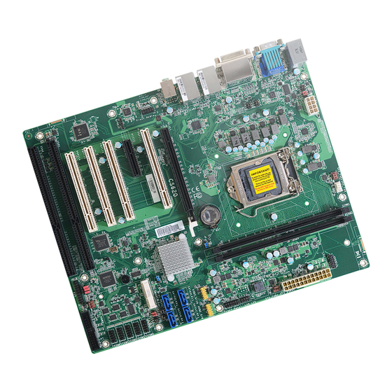
Chapter 2 HARDWARE INSTALLATION Chapter 2 - Hardware Installation X Board Layout Note: Some optional components are only available upon request. DDR4_1 USB 2.0 System (USB 6/5) +12V Power Fan 1 PS/2 KB/MS Important: TSJP2 TSJP1 Electrostatic discharge (ESD) can damage your board, processor, COM 1 disk drives, add-in boards, and other components. -
Page 9: System Memory
Chapter 2 HARDWARE INSTALLATION X System Memory System Memory Installing the DIMM Module Before installing the memory module, please make sure that the following safety cau- tions are well-attended. 1. Make sure the PC and all other peripheral devices connected to it has been DDR4_1 System +12V Power... -
Page 10: Removing The Dimm Module
Chapter 2 HARDWARE INSTALLATION System Memory Installing the DIMM Module System Memory Removing the DIMM Module Please follow the steps below to install the memory card into the socket. Please follow the steps below to remove the memory card from the socket. Step 1: Memory Module Memory Module... -
Page 11: Cpu
Chapter 2 HARDWARE INSTALLATION X CPU Installing the CPU 1. Make sure the PC and all other peripheral devices connected to it have been powered down. The system board is equipped with a surface mount LGA 1151 socket. This socket is exclu- sively designed for installing a LGA 1151 packaged Intel CPU. - Page 12 Chapter 2 HARDWARE INSTALLATION Installing the CPU Installing the CPU 5. Lift the load lever and the load plate all the way up as shown in Load lever 7-2. Two keys on the socket the photo. and notches on the CPU Alignment key also facilitate alignment.
-
Page 13: Installing The Fan And Heat Sink
Chapter 2 HARDWARE INSTALLATION Installing the Fan and Heat Sink 4. Screw tight two of the spring screws at opposite corners into the mounting holes. And then proceed with the other two spring screws. The CPU must be kept cool by using a CPU fan with heat sink. Without sufficient air circula- tion across the CPU and heat sink, the CPU will overheat damaging both the CPU and system board. -
Page 14: Jumper Settings
Chapter 2 HARDWARE INSTALLATION X Jumper Settings COM 1 Serial Mode Clear CMOS TSJP2 DDR4_1 System +12V Power Fan 1 COM 1 TSJP2 TSJP1 Socket LGA1151 DDR4_1 TSJP3 (upper) System +12V Power Fan 1 TSJP3 TSJP4 TSJP2 TSJP1 TSJP4 (lower) Socket LGA1151 TSJP3 SPI Flash... -
Page 15: Com 2 Serial Mode
Chapter 2 HARDWARE INSTALLATION Jumper Settings Jumper Settings COM 2 Serial Mode COM 1/2 RS232 Power Select TSJP1 (right) DDR4_1 System +12V Power Fan 1 TSJP2 TSJP1 Socket LGA1151 DDR4_1 System +12V Power TSJP3 Fan 1 TSJP4 TSJP2 TSJP1 Socket LGA1151 TSJP6/7/8 TSJP3 SPI Flash... -
Page 16: Sata Port0 / Msata Switch
Chapter 2 HARDWARE INSTALLATION Jumper Settings Jumper Settings SATA port0 / mSATA Switch Digital I/O (DIO) Power Supply DDR4_1 System +12V Power Fan 1 DDR4_1 System TSJP2 TSJP1 +12V Power Fan 1 Socket LGA1151 TSJP2 TSJP1 Socket LGA1151 TSJP3 TSJP4 TSJP3 TSJP4 SPI Flash... -
Page 17: Digital I/O (Dio) Power Select
Chapter 2 HARDWARE INSTALLATION Jumper Settings Digital I/O (DIO) Power Select DDR4_1 System +12V Power Fan 1 TSJP2 TSJP1 Socket LGA1151 TSJP3 TSJP4 SPI Flash Intel I219V BIOS 1 1 1 Intel I211AT Battery DDR4_2 PCIe 1 (PCIe x16) PCI 1 Realtek Intel ALC887... -
Page 18: Rear I/O Ports
Chapter 2 HARDWARE INSTALLATION X Rear I/O Ports Rear I/O Ports PS/2 Keyboard/Mouse „ PS/2 „ COM 1 KB/MS „ LAN 1 „ LAN 2 „ DVI-I DDR4_1 System „ Audio +12V Power Fan 1 „ PS/2 KB/MS TSJP2 TSJP1 Socket LGA1151 TSJP3 TSJP4... -
Page 19: Usb Ports
Chapter 2 HARDWARE INSTALLATION Rear I/O Ports Rear I/O Ports USB Ports Graphics Display DDR4_1 DDR4_1 System System +12V Power +12V Power Fan 1 Fan 1 TSJP2 TSJP1 TSJP2 TSJP1 Socket LGA1151 Socket LGA1151 „ USB 8 (USB 2.0) TSJP3 TSJP3 TSJP4 TSJP4... -
Page 20: Rj45 Lan
Chapter 2 HARDWARE INSTALLATION Rear I/O Ports Rear I/O Ports RJ45 LAN Audio DDR4_1 System DDR4_1 System +12V Power Fan 1 +12V Power Fan 1 TSJP2 TSJP1 TSJP2 TSJP1 Socket LGA1151 Socket LGA1151 TSJP3 TSJP3 „ LAN 1 „ LAN 2 TSJP4 TSJP4 SPI Flash... -
Page 21: Com 1 (Serial) Port
Chapter 2 HARDWARE INSTALLATION Rear I/O Ports X Internal I/O Connectors COM 1 (Serial) Port COM (Serial) Ports „ COM 1 DDR4_1 System +12V Power Fan 1 TSJP2 TSJP1 Socket LGA1151 DDR4_1 System +12V Power Fan 1 TSJP3 TSJP2 TSJP1 TSJP4 Socket LGA1151 TSJP3... -
Page 22: Usb Ports
Chapter 2 HARDWARE INSTALLATION Internal I/O Connectors COM (Serial) Ports Internal I/O Connectors USB Ports „ Internal COM Port Pin Assignment DDR4_1 System +12V Power Fan 1 TSJP2 TSJP1 Socket LGA1151 „ USB 9/10 (left), TSJP3 Standard RS232 with Power RS422 RS485 TSJP4... -
Page 23: Front Audio
Chapter 2 HARDWARE INSTALLATION Internal I/O Connectors Internal I/O Connectors Front Audio SATA (Serial ATA) DDR4_1 System DDR4_1 +12V Power System Fan 1 +12V Power Fan 1 TSJP2 TSJP1 TSJP2 TSJP1 Socket LGA1151 Socket LGA1151 TSJP3 TSJP3 TSJP4 TSJP4 SATA0~3 „... -
Page 24: Digital I/O
Chapter 2 HARDWARE INSTALLATION Internal I/O Connectors Internal I/O Connectors Digital I/O Cooling Fan Connectors System Fan 1 (left), CPU Fan (right) DDR4_1 System +12V Power Fan 1 DDR4_1 TSJP2 TSJP1 System +12V Power Fan 1 Socket LGA1151 TSJP2 TSJP1 Socket LGA1151 TSJP3 TSJP4... -
Page 25: Power Connector
Chapter 2 HARDWARE INSTALLATION Internal I/O Connectors Internal I/O Connectors Power Connector Chassis Intrusion „ ATX 24-pin Power DDR4_1 Connector System +12V Power Fan 1 DDR4_1 TSJP2 TSJP1 System +12V Power Fan 1 Socket LGA1151 TSJP2 TSJP1 12 24 TSJP3 Socket LGA1151 TSJP4 +3.3V TSJP3... -
Page 26: Front Panel
Chapter 2 HARDWARE INSTALLATION Internal I/O Connectors Internal I/O Connectors Front Panel S/PDIF DDR4_1 System +12V Power Fan 1 TSJP2 TSJP1 Socket LGA1151 DDR4_1 System TSJP3 +12V Power Fan 1 TSJP4 TSJP2 TSJP1 Socket LGA1151 PWR-LED TSJP3 SPI Flash HD-LED Intel I219V BIOS TSJP4... -
Page 27: Battery
Chapter 2 HARDWARE INSTALLATION Internal I/O Connectors Internal I/O Connectors Battery SMBus DDR4_1 System +12V Power Fan 1 DDR4_1 System +12V Power TSJP2 TSJP1 Fan 1 Socket LGA1151 TSJP2 TSJP1 Socket LGA1151 TSJP3 TSJP4 TSJP3 TSJP4 SPI Flash Intel I219V BIOS SPI Flash Intel I219V... -
Page 28: Lpc
External COM port Module The LPC connector is used for debugging. The external COM port modules — EXT-RS232 and EXT-RS485 — are designed by DFI’s propri- etary technology, and support four additional COM ports per module. The EXT-RS232/RS485 card is connected to the motherboard via the LPC connector and secured by a standoff as illustrated below. -
Page 29: Lan Led
Chapter 2 HARDWARE INSTALLATION Internal I/O Connectors Internal I/O Connectors LAN LED Expansion Slots DDR4_1 System DDR4_1 +12V Power System Fan 1 +12V Power Fan 1 TSJP2 TSJP1 TSJP2 TSJP1 Socket LGA1151 Socket LGA1151 TSJP3 TSJP3 TSJP4 TSJP4 „ LAN LED Connector SPI Flash Intel I219V SPI Flash... -
Page 30: Installing The Mini Pcie Module
Chapter 2 HARDWARE INSTALLATION Internal I/O Connectors Expansion Slots Internal I/O Connectors Expansion Slots Installing the Mini PCIe Module DDR4_1 Before installing the Mini PCIe module into the Mini PCIe socket, please make sure that the System +12V Power Fan 1 following safety cautions are well-attended. -
Page 31: Chapter 3 - Bios Settings
Chapter 3 BIOS SETTINGS Chapter 3 - BIOS Settings Legends X Overview Keys Function The BIOS is a program that takes care of the basic level of communication between the CPU and peripherals. It contains codes for various advanced features found in this system board. Right / Left arrow Move the highlight left or right to select a menu The BIOS allows you to configure the system and save the configuration in a battery-backed... -
Page 32: Main
Chapter 3 BIOS SETTINGS X Main X Advanced The Main menu is the first screen that you will see when you enter the BIOS Setup Utility. The Advanced menu allows you to configure your system for basic operation. Some entries are defaults required by the system board, while others, if enabled, will improve the performance of your system or let you set some features according to your preference. -
Page 33: Rc Acpi Configuration
Chapter 3 BIOS SETTINGS Advanced Advanced RC ACPI Configuration CPU Configuration Aptio Setup Utility - Copyright (C) 2020 American Megatrends, Inc. Aptio Setup Utility - Copyright (C) 2020 American Megatrends, Inc. Advanced Advanced CPU Configuration When enabled, a VMM can RC ACPI Configuration Enable or disable System utilize the additional hard-... -
Page 34: Power & Performance
Chapter 3 BIOS SETTINGS Advanced Advanced Power & Performance PCH-FW Configuration Aptio Setup Utility - Copyright (C) 2020 American Megatrends, Inc. Aptio Setup Utility - Copyright (C) 2020 American Megatrends, Inc. Advanced Advanced ME State [Enabled] When Disabled ME will be Power &... - Page 35 Chapter 3 BIOS SETTINGS Advanced PCH-FW Configuration ► Firmware Update Configuration Aptio Setup Utility - Copyright (C) 2020 American Megatrends, Inc. Advanced Me FW Image Re-Flash [Disable] Enable/Disable Me FW Im- age Re-Flash function. →←: Select Screen ↑↓: Select Item Enter: Select +/- : Change Opt.
-
Page 36: Trusted Computing
Chapter 3 BIOS SETTINGS Advanced Advanced Trusted Computing NCT6116D Super IO Configuration Aptio Setup Utility - Copyright (C) 2020 American Megatrends, Inc. Aptio Setup Utility - Copyright (C) 2020 American Megatrends, Inc. Advanced Advanced TPM20 Device Found Enables or Disables BIOS NCT6116D Super IO Configuration WatchDog Timer Unit Se- Firmware Version... -
Page 37: Nct6116D Hw Monitor
Chapter 3 BIOS SETTINGS Advanced NCT6116D Super IO Configuration Advanced ► Serial Port 1/2/3/4/5/6 and Parallel Port Configuration NCT6116D HW Monitor Aptio Setup Utility - Copyright (C) 2020 American Megatrends, Inc. Aptio Setup Utility - Copyright (C) 2020 American Megatrends, Inc. Advanced Advanced Serial Port 1 Configuration... -
Page 38: Serial Port Console Redirection
Chapter 3 BIOS SETTINGS Advanced NCT6116D HW Monitor Advanced ► Smart Fan Function Serial Port Console Redirection Aptio Setup Utility - Copyright (C) 2020 American Megatrends, Inc. Aptio Setup Utility - Copyright (C) 2020 American Megatrends, Inc. Advanced Advanced Enable CPU SmartFan Console Redirection En - Smart Fan Function COM1... -
Page 39: Usb Configuration
Chapter 3 BIOS SETTINGS Advanced Serial Port Console Redirection Advanced ► Console Redirection Settings USB Configuration Aptio Setup Utility - Copyright (C) 2020 American Megatrends, Inc. Aptio Setup Utility - Copyright (C) 2020 American Megatrends, Inc. Advanced Advanced Enable CPU SmartFan Enables Legacy USB sup- COM1 USB Configuration... -
Page 40: Csm Configuration
Chapter 3 BIOS SETTINGS Advanced Advanced CSM Configuration USB Power Control Aptio Setup Utility - Copyright (C) 2020 American Megatrends, Inc. Aptio Setup Utility - Copyright (C) 2020 American Megatrends, Inc. Advanced Advanced Enable/Disable CSM Sup- Enable/Disable UEFI Net- Compatibility Support Module Configuration USB2_1/2 [Enabled] port. -
Page 41: Network Stack Configuration
Chapter 3 BIOS SETTINGS Advanced Network Stack Configuration Aptio Setup Utility - Copyright (C) 2020 American Megatrends, Inc. Advanced Enable/Disable UEFI Net- Network Stack [Enabled] work Stack Ipv4 PXE Support [Disabled] Ipv6 PXE Support [Disabled] PXE boot wait time Media detect count →←: Select Screen ↑↓: Select Item Enter: Select... -
Page 42: Chipset
Chapter 3 BIOS SETTINGS X Chipset Chipset Graphics Configuration Aptio Setup Utility - Copyright (C) 2020 American Megatrends, Inc. Aptio Setup Utility - Copyright (C) 2020 American Megatrends, Inc. Main Advanced Chipset Security Boot Save & Exit Chipset ► Graphics Configuration Initial priority : Graphics Configuration Graphics Configuration... -
Page 43: Peg Port Configuration
Chapter 3 BIOS SETTINGS Chipset PEG Port Configuration ► PEG Port Feature Configuration Aptio Setup Utility - Copyright (C) 2020 American Megatrends, Inc. Aptio Setup Utility - Copyright (C) 2020 American Megatrends, Inc. Chipset Chipset Enable or Disable the Root Detect Non-Compliance PCI PEG Port Configuration PEG Port Feature Configuration... -
Page 44: Pch-Io Configuration
Chapter 3 BIOS SETTINGS Chipset Chipset PCH-IO Configuration PCH-IO Configuration PCI Express Configuration Aptio Setup Utility - Copyright (C) 2020 American Megatrends, Inc. Aptio Setup Utility - Copyright (C) 2020 American Megatrends, Inc. Chipset Chipset PCI Express Configuration PCI Express Root Port Set- PCH-IO Configuration PCI Express Configuration settings... -
Page 45: Sata And Rst Configuration
Chapter 3 BIOS SETTINGS Chipset PCH-IO Configuration Chipset PCH-IO Configuration SATA And RST Configuration HD Audio Configuration Aptio Setup Utility - Copyright (C) 2020 American Megatrends, Inc. Aptio Setup Utility - Copyright (C) 2020 American Megatrends, Inc. Chipset Chipset SATA And RST Configuration E n a b l e o r d i s a b l e S ATA Control Detection of the HD Audio Subsystem Configuration Settings... -
Page 46: Security
Chapter 3 BIOS SETTINGS X Security Security Secure Boot Aptio Setup Utility - Copyright (C) 2020 American Megatrends, Inc. Aptio Setup Utility - Copyright (C) 2020 American Megatrends, Inc. Main Advanced Chipset Security Boot Save & Exit Security Password Description S e t A d m i n i s t r a t o r P a s s - System Mode Setup... -
Page 47: Boot
Chapter 3 BIOS SETTINGS X Boot X Save & Exit Aptio Setup Utility - Copyright (C) 2020 American Megatrends, Inc. Aptio Setup Utility - Copyright (C) 2020 American Megatrends, Inc. Main Advanced Chipset Security Boot Save & Exit Main Advanced Chipset Security Boot... -
Page 48: Updating The Bios
BIOS with the flash utility. For updating AMI BIOS in UEFI mode, you may refer to the how-to video at https://www.dfi.com/Knowledge/Video/5. X Notice: BIOS SPI ROM 1.
Need help?
Do you have a question about the CS620-H310C and is the answer not in the manual?
Questions and answers