Table of Contents
Advertisement
Quick Links
The DRV2605EVM-BT is an evaluation kit for the DRV2605 ERM and LRA Haptic Driver. The kit connects
the DRV2605 to an iOS App. wirelessly over Bluetooth Low Energy to allow control, creation, and
customization of haptic effects. Use the included app to demonstrate the use of haptics in smart watches,
fitness trackers, wearable devices, or to "haptify" any application without having to connect wires
externally to a micro-controller. The app. includes notification demos, waveform playback, and DRV2605
register control.
The DRV2605 contains an embedded waveform library licensed from Immersion that supports driving
eccentric rotating mass motors (ERM) or linear resonant actuators (LRA). With the included LRA, mount it
and immediately begin using the DRV2605 library through the iOS App. The DRV2605EVM-BT can also
be powered either by a 5V USB power supply using the included micro-USB cable or by 3xAAA batteries
using the included battery pack with JST connector.
...................................................................................................................
1
2
3
4
5
6
7
Updating Firmware on DRV2605EVM-BT
8
Schematics, PCB Layers, and Bill of Materials
1
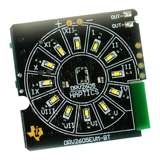
Top View of DRV2605EVM-BT
2
Bottom View of DRV2605EVM-BT
3
Smart Haptic Driver
4
Battery / Power Source Management
5
Buck-Boost Converter for Board Supply
6
Startup Screen
7
8
9
10
11
12
13
14
15
2
16
17
18
19
X-Ray Top View
....................................................................................................................
20
Top Layer
.................................................................................................................
21
Top Overlay
SLOU391 - May 2014
Submit Documentation Feedback
.....................................................................................................
...............................................................................................................
...............................................................................................
..........................................................................................................
.........................................................................................................
..............................................................................
............................................................................................
........................................................................................
..........................................................................................................
.....................................................................................
..................................................................................
..............................................................................................................
........................................................................................................
..............................................................................................................
......................................................................................................
........................................................................................................
.................................................................................................
....................................................................................................
............................................................................................................
..................................................................................
.............................................................................................................
............................................................................................................
Copyright © 2014, Texas Instruments Incorporated
DRV2605EVM-BT User's Guide
Contents
.........................................................................
List of Figures
..................................................................
..........................................................................
User's Guide
SLOU391 - May 2014
.....................................
DRV2605EVM-BT User's Guide
2
2
3
4
5
10
18
20
3
3
5
6
7
11
11
12
13
14
14
14
15
16
16
17
19
19
22
22
23
1
Advertisement
Table of Contents

Subscribe to Our Youtube Channel
Related Manuals for Texas Instruments DRV2605


Summary of Contents for Texas Instruments DRV2605
-
Page 1: Table Of Contents
SLOU391 – May 2014 DRV2605EVM-BT User's Guide The DRV2605EVM-BT is an evaluation kit for the DRV2605 ERM and LRA Haptic Driver. The kit connects the DRV2605 to an iOS App. wirelessly over Bluetooth Low Energy to allow control, creation, and customization of haptic effects. -
Page 2: Introduction
The DRV2605 offers the integrated Immersion TS2200 waveform library, which consists of 123 patterns for eccentric rotating mass (ERM) and linear resonant actuator (LRA) that can be selected, sequenced, and streamed from the iOS application on to the DRV2605EVM-BT. Other novel features of the DRV2605 are: •... -
Page 3: Getting Started
Getting Started www.ti.com Getting Started Figure 1. Top View of DRV2605EVM-BT Figure 2. Bottom View of DRV2605EVM-BT SLOU391 – May 2014 DRV2605EVM-BT User's Guide Submit Documentation Feedback Copyright © 2014, Texas Instruments Incorporated... -
Page 4: Steps To Connect To The App
Steps to Connect to the App The iOS app is available in the Apple App Store as “TI Haptic Bluetooth Kit” by Texas Instruments. It is ® compatible with iPod touch and iPhone with iOS7 operating system or later. Download and install the ®... -
Page 5: Hardware Overview
The DRV2605EVM-BT’s DRV2605 haptic driver is powered by onboard bq24232 battery management chip. The DRV2605 is capable of driving ERM and LRA actuators. The BLE microcontroller's I2C, EN and trigger pins are connected to the DRV2605. There are 123 library effects embedded inside the DRV2605. - Page 6 DC-DC converter is operational. The board is configured in PFM mode through a resistor R37 which pulls the PFM/PWM pin to low. The REGVDD is the fixed 3.3-V rail for the board. DRV2605EVM-BT User's Guide SLOU391 – May 2014 Submit Documentation Feedback Copyright © 2014, Texas Instruments Incorporated...
- Page 7 VBQOUT REG_VDD VOUT 4.7µF 10µF 10.0k 10µF 47µF ILIM0 PFM/PWM ILIM1 VBQOUT Yellow TPS63051YFF VBQOUT 1.50k 1000pF Figure 5. Buck-Boost Converter for Board Supply SLOU391 – May 2014 DRV2605EVM-BT User's Guide Submit Documentation Feedback Copyright © 2014, Texas Instruments Incorporated...
- Page 8 C lines compatible with user friendly 100-mil spacing headers. They can be used to connect external microcontrollers. The TRG testpoint can be used to provide PWM input to the DRV2605. See Section 5.11 to learn more about converting the audio signal to haptic effects.
- Page 9 S2 is a load switch which connects and disconnects the battery. Turn S2 to ON position if using an external battery to power the board. OUT– and OUT+ These pads are the output of the DRV2605. A vibration motor like an ERM or LRA can be connected to these pads. 5.10 LEDs LEDs I to XII: These white LEDs arranged in a clock-like orientation, can display time synced from the iOS device and demonstrate visible alerts from notification menu.
-
Page 10: Ios App Overview
DRV2605. located here. use cases. of the smart driver. Section 6.2.1 Section 6.2.2 Section 6.2.3 Section 6.2.4 Section 6.3.1 Section 6.3.2 DRV2605EVM-BT User's Guide SLOU391 – May 2014 Submit Documentation Feedback Copyright © 2014, Texas Instruments Incorporated... -
Page 11: Connection Overlay
DRV2605EVM-BT and a connection overlay appears during the process as shown in Figure 7 before showing the next screen. Figure 6. Startup Screen Figure 7. Connection Overlay SLOU391 – May 2014 DRV2605EVM-BT User's Guide Submit Documentation Feedback Copyright © 2014, Texas Instruments Incorporated... -
Page 12: Ios App Menu
Stock Waveforms The stock waveforms submenu consists of a select few waveforms from the ROM libraries of the DRV2605. The list shows nine waveforms. These haptic patterns can be triggered by touch-selecting the respective pattern. The user can navigate between screens either by swiping from left to right (as shown in... -
Page 13: Waveform Sequencer
6.2.3 Waveform Sequencer The Waveform Sequencer submenu allows you to load up to eight sequences on the sequencer of the DRV2605. The list shown in Figure 9 is scrollable and contains 123 patterns from the effects library. Click on the + and – buttons to add or remove a waveform. As an option, the user can click the Play All button... -
Page 14: Notifications Screen
The table on the bottom half of the screen is the haptic notification. The user can either choose the waveforms from the Your Waveforms list or select a pattern from the 123 DRV2605 ROM libraries. DRV2605EVM-BT User's Guide SLOU391 – May 2014 Submit Documentation Feedback Copyright © 2014, Texas Instruments Incorporated... -
Page 15: Notification Haptic And Led Effect Selection Screen
IOS App Overview www.ti.com Figure 13. Notification Haptic and LED Effect Selection Screen SLOU391 – May 2014 DRV2605EVM-BT User's Guide Submit Documentation Feedback Copyright © 2014, Texas Instruments Incorporated... -
Page 16: Led Playground
(fps) in a video. Less time on the slider results in more frames per second of the LED movie. The application also has a Game of Life sequence embedded. Figure 14. LED Playground Figure 15. LED Playground with Sample LEDs Selected DRV2605EVM-BT User's Guide SLOU391 – May 2014 Submit Documentation Feedback Copyright © 2014, Texas Instruments Incorporated... -
Page 17: C Keypad - Register Control Screen
The overdrive clamp controls how much of a startup push is given to the motor. The overdrive feature of the DRV2605 makes the effects crisp. It is usually 1.5× to 2x higher than the rated voltage, but check the actuator data sheet for more information. -
Page 18: Cc Debugger
9. Click Perform Actions and wait until the process is complete. 10. After a success message, the board is ready with the new firmware image. DRV2605EVM-BT User's Guide SLOU391 – May 2014 Submit Documentation Feedback Copyright © 2014, Texas Instruments Incorporated... -
Page 19: Tag-Connect Tc2050-Idc-Nl 10-Pin No-Legs Cable With Ribbon Connector
Updating Firmware on DRV2605EVM-BT www.ti.com Figure 17. CC – Debugger Figure 18. Tag-Connect TC2050-IDC-NL 10-Pin No-legs Cable with Ribbon Connector SLOU391 – May 2014 DRV2605EVM-BT User's Guide Submit Documentation Feedback Copyright © 2014, Texas Instruments Incorporated... - Page 20 Not in version control Assembly Variant:001 Sheet: warrant that this design will meet the specifications, will be suitable for your application or fit for any particular purpose, or will operate in an implementation. Texas Instruments and/or its Drawn By: Gautham Ramachandran File: AIP029A.SchDoc...
- Page 21 Not in version control Assembly Variant:001 Sheet: warrant that this design will meet the specifications, will be suitable for your application or fit for any particular purpose, or will operate in an implementation. Texas Instruments and/or its Drawn By: Gautham Ramachandran File: AIP029A_Hardware.SchDoc...
- Page 22 Schematics, PCB Layers, and Bill of Materials www.ti.com PCB Layers Figure 19. X-Ray Top View Figure 20. Top Layer DRV2605EVM-BT User's Guide SLOU391 – May 2014 Submit Documentation Feedback Copyright © 2014, Texas Instruments Incorporated...
- Page 23 Schematics, PCB Layers, and Bill of Materials www.ti.com Figure 21. Top Overlay Figure 22. Mid-Layer 1 SLOU391 – May 2014 DRV2605EVM-BT User's Guide Submit Documentation Feedback Copyright © 2014, Texas Instruments Incorporated...
- Page 24 Schematics, PCB Layers, and Bill of Materials www.ti.com Figure 23. Mid-Layer 2 Figure 24. Bottom Layer DRV2605EVM-BT User's Guide SLOU391 – May 2014 Submit Documentation Feedback Copyright © 2014, Texas Instruments Incorporated...
- Page 25 Schematics, PCB Layers, and Bill of Materials www.ti.com Figure 25. Bottom Overlay Figure 26. Board Dimensions SLOU391 – May 2014 DRV2605EVM-BT User's Guide Submit Documentation Feedback Copyright © 2014, Texas Instruments Incorporated...
- Page 26 Schematics, PCB Layers, and Bill of Materials www.ti.com Figure 27. Top Solder Figure 28. Bottom Solder DRV2605EVM-BT User's Guide SLOU391 – May 2014 Submit Documentation Feedback Copyright © 2014, Texas Instruments Incorporated...
- Page 27 Schematics, PCB Layers, and Bill of Materials www.ti.com Figure 29. Drill Drawing Figure 30. Drill Table SLOU391 – May 2014 DRV2605EVM-BT User's Guide Submit Documentation Feedback Copyright © 2014, Texas Instruments Incorporated...
- Page 28 Inductor, Multilayer, Ferrite, 1uH, 0.8A, 0.19 ohm, 1 uH 0805 LQM21PN1R0MC0D MuRata R1, R8, R12, R33 10.0k RES, 10.0k ohm, 1%, 0.063W, 0402 0402 CRCW040210K0FKED Vishay-Dale DRV2605EVM-BT User's Guide SLOU391 – May 2014 Submit Documentation Feedback Copyright © 2014, Texas Instruments Incorporated...
- Page 29 RES, 0 ohm, 5%, 0.063W, 0402 0402 CRCW04020000Z0ED Vishay-Dale R43, R45 QFN, 4 x 0.95 x Motion Processing Unit, QFN-24 IMU-3000 InvenSense 4 mm Alternate manufacturer not available. SLOU391 – May 2014 DRV2605EVM-BT User's Guide Submit Documentation Feedback Copyright © 2014, Texas Instruments Incorporated...
- Page 30 Operation of this equipment in a residential area is likely to cause harmful interference in which case the user will be required to correct the interference at his own expense. SPACER SPACER SPACER SPACER SPACER SPACER SPACER DRV2605EVM-BT User's Guide SLOU391 – May 2014 Submit Documentation Feedback Copyright © 2014, Texas Instruments Incorporated...
- Page 31 Please note that if User does not follow the instructions above, User will be subject to penalties of Radio Law of Japan. SPACER SPACER SLOU391 – May 2014 DRV2605EVM-BT User's Guide Submit Documentation Feedback Copyright © 2014, Texas Instruments Incorporated...
- Page 32 However, TI does not warrant the accuracy of EVM descriptions, EVM availability or other information on its websites as accurate, complete, reliable, current, or error-free. DRV2605EVM-BT User's Guide SLOU391 – May 2014 Submit Documentation Feedback Copyright © 2014, Texas Instruments Incorporated...
- Page 33 County, Texas. Notwithstanding the foregoing, any judgment may be enforced in any United States or foreign court, and TI may seek injunctive relief in any United States or foreign court. SLOU391 – May 2014 DRV2605EVM-BT User's Guide Submit Documentation Feedback Copyright © 2014, Texas Instruments Incorporated...
- Page 34 IMPORTANT NOTICE Texas Instruments Incorporated and its subsidiaries (TI) reserve the right to make corrections, enhancements, improvements and other changes to its semiconductor products and services per JESD46, latest issue, and to discontinue any product or service per JESD48, latest issue.
Need help?
Do you have a question about the DRV2605 and is the answer not in the manual?
Questions and answers