Advertisement
Quick Links
www.ti.com
EVM User's Guide: DRV8334EVM
DRV8334 Evaluation Module
Description
The DRV8334EVM is a 30 A, 3-phase brushless DC
drive stage based on the DRV8334 gate driver for
BLDC motors.
The EVM allows quick evaluation of the DRV8334
device which spins a BLDC motor with trapezoidal
commutation and control.
Status LEDs for all power supplies as well as a
Fault LED are included for user feedback. The C2000
launchpad (LAUNCHXL-F280049C) is required for
this kit and is used to control the DRV8334 as well
as monitor and report faults.
SLVUCU7 – NOVEMBER 2023
Submit Document Feedback
Features
•
4.5V to 60 V operation with support for 12 V/24 V
applications
•
100% duty cycle PWM control, with 1 A/2 A peak
gate drive
•
40+ configurable IDRIVE steps for fine slew rate
tuning
•
3x integrated CSAs with low input offset drift
Applications
•
Appliances,
lawnmowers
•
Brushless-DC (BLDC) motor modules
•
Fans, pumps,
•
E-bikes, e-scooters, and e-mobility
•
Cordless vacuum cleaners
•
Drones,
toys
DRV8334EVM
Copyright © 2023 Texas Instruments Incorporated
cordless garden
and
power
and
servo drives
industrial and logistics
robots, and
DRV8334 Evaluation Module
Description
tools,
and PMSM
RC
1
Advertisement

Related Manuals for Texas Instruments DRV8334


Summary of Contents for Texas Instruments DRV8334
- Page 1 Fault LED are included for user feedback. The C2000 launchpad (LAUNCHXL-F280049C) is required for • Appliances, cordless garden power tools, this kit and is used to control the DRV8334 as well lawnmowers as monitor and report faults. • Brushless-DC (BLDC) motor modules and PMSM •...
- Page 2 This document is intended for the engineers involved in the design, implementation, and validation of DRV8334 + TMS320F280049C reference software. The scope of this document is to provide the user with a guide to evaluate the DRV8334 device with a TMS320F280049C board. This document covers the hardware connections required between boards and external motor/supplies.
-
Page 3: Kit Contents
1.2 Kit Contents Item Description Quantity DRV8334EVM Cardboard box Label Standard label Foam Antistatic foam Literature EVM disclaimers SLVUCU7 – NOVEMBER 2023 DRV8334 Evaluation Module Submit Document Feedback Copyright © 2023 Texas Instruments Incorporated... -
Page 4: Specification
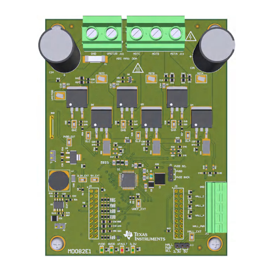
Figure 1-2. 3-phase BLDC Driver Simplified Schematic 1.4 Device Information The DRV8334 enables customers to evaluate their motor performance within their gate driver system. The DRV8334 implements features such as enhanced Smart Gate Drive and expanded device protection features, making the device an excellent choice for applications such as power tools, appliances, pumps, and fans. The device supports both 12 V and 24 V applications while allowing up to 65 V PVDD abs max to support power supply transients. - Page 5 The following section describes the EVM hardware and connections to the external supply, hall sensors, PC via USB, and motor. Figure 2-1. EVM Board Overview SLVUCU7 – NOVEMBER 2023 DRV8334 Evaluation Module Submit Document Feedback Copyright © 2023 Texas Instruments Incorporated...
- Page 6 VMOTOR input is fused with a 30 A fuse and the input connector is rated for 32 A. DRV8334 Evaluation Module SLVUCU7 – NOVEMBER 2023 Submit Document Feedback Copyright © 2023 Texas Instruments Incorporated...
- Page 7 If the motor phases do not match the hall sensors or the connections are made out of order, then the motor does not spin smoothly and current consumption increases. The three phase inputs of the motor connect to MOTA/MOTB/MOTC through connector J13. SLVUCU7 – NOVEMBER 2023 DRV8334 Evaluation Module Submit Document Feedback Copyright © 2023 Texas Instruments Incorporated...
- Page 8 Jumper J7 connects the PVDD buck output (12V) to the 3.3V LDO. Remove this jumper to power down the 3.3V rail. GVDD is generated internally to the DRV8334 device and the options are explained in the complete data sheet. DRV8334 Evaluation Module SLVUCU7 –...
- Page 9 VMOTOR range is 5 V to 60 V. 6. Start the GUI per the instructions below in Section 3.1. SLVUCU7 – NOVEMBER 2023 DRV8334 Evaluation Module Submit Document Feedback Copyright © 2023 Texas Instruments Incorporated...
- Page 10 2. Take the DRV8334 out of sleep mode by toggling nSLEEP to WAKE. 3. Enable the PWM using the Output Enable toggle switch. a. The DRV8334 reports no faults (Fault LED green on GUI, no red nFAULT LED on the EVM) and VMOTOR/GVDD voltage is reported by the GUI.
- Page 11 3. Click anywhere on the screen to deselect the text input field. 4. Click SPI WRITE or SPI READ to send the command to the DRV8334. If the text field is not deselected first, then click the SPI WRITE or SPI READ a second time to execute the transaction.
- Page 12 Hardware Design Files www.ti.com 4 Hardware Design Files 4.1 Schematics Figure 4-1. Schematic 1 DRV8334 Evaluation Module SLVUCU7 – NOVEMBER 2023 Submit Document Feedback Copyright © 2023 Texas Instruments Incorporated...
- Page 13 Hardware Design Files Figure 4-2. Schematic 2 SLVUCU7 – NOVEMBER 2023 DRV8334 Evaluation Module Submit Document Feedback Copyright © 2023 Texas Instruments Incorporated...
- Page 14 Hardware Design Files www.ti.com Figure 4-3. Schematic 3 DRV8334 Evaluation Module SLVUCU7 – NOVEMBER 2023 Submit Document Feedback Copyright © 2023 Texas Instruments Incorporated...
- Page 15 Hardware Design Files Figure 4-4. Schematic 4 SLVUCU7 – NOVEMBER 2023 DRV8334 Evaluation Module Submit Document Feedback Copyright © 2023 Texas Instruments Incorporated...
-
Page 16: Pcb Layouts
Hardware Design Files www.ti.com 4.2 PCB Layouts Figure 4-5. EVM Dimensions DRV8334 Evaluation Module SLVUCU7 – NOVEMBER 2023 Submit Document Feedback Copyright © 2023 Texas Instruments Incorporated... - Page 17 Hardware Design Files Figure 4-6. EVM Top Overlay SLVUCU7 – NOVEMBER 2023 DRV8334 Evaluation Module Submit Document Feedback Copyright © 2023 Texas Instruments Incorporated...
- Page 18 Hardware Design Files www.ti.com Figure 4-7. EVM Top Layer DRV8334 Evaluation Module SLVUCU7 – NOVEMBER 2023 Submit Document Feedback Copyright © 2023 Texas Instruments Incorporated...
- Page 19 Hardware Design Files Figure 4-8. EVM Signal Layer 1 SLVUCU7 – NOVEMBER 2023 DRV8334 Evaluation Module Submit Document Feedback Copyright © 2023 Texas Instruments Incorporated...
- Page 20 Hardware Design Files www.ti.com Figure 4-9. EVM Signal Layer 2 DRV8334 Evaluation Module SLVUCU7 – NOVEMBER 2023 Submit Document Feedback Copyright © 2023 Texas Instruments Incorporated...
- Page 21 Hardware Design Files Figure 4-10. EVM Bottom Layer SLVUCU7 – NOVEMBER 2023 DRV8334 Evaluation Module Submit Document Feedback Copyright © 2023 Texas Instruments Incorporated...
- Page 22 Hardware Design Files www.ti.com Figure 4-11. EVM Bottom Overlay DRV8334 Evaluation Module SLVUCU7 – NOVEMBER 2023 Submit Document Feedback Copyright © 2023 Texas Instruments Incorporated...
- Page 23 CAP, CERM, 47 uF, 25 V, +/- 20%, 47uF 1206_190 C3216X5R1E476M160AC X5R, 1206_190 C31, C32, C51, CAP, CERM, 0.1 uF, 16 V, +/- 5%, 0.1uF 0603 C0603C104J4RAC7867 Kemet X7R, 0603 SLVUCU7 – NOVEMBER 2023 DRV8334 Evaluation Module Submit Document Feedback Copyright © 2023 Texas Instruments Incorporated...
- Page 24 Terminal Block, 9.52mm, 3x1, R/A, TH 1904150 Phoenix Contact Pitch 9.52mm Inductor, Drum Core, Ferrite, 68 uH, 68uH SDR1006 SDR1006-680KL Bourns 1.1 A, 0.22 ohm, SMD DRV8334 Evaluation Module SLVUCU7 – NOVEMBER 2023 Submit Document Feedback Copyright © 2023 Texas Instruments Incorporated...
- Page 25 100k 0603 CRCW0603100KFKEA Vishay-Dale R76, R77, R78 Grade 0, 0603 RES, 100 k, 1%, 0.063 W, AEC-Q200 100k 0402 CRCW0402100KFKED Vishay-Dale Grade 0, 0402 SLVUCU7 – NOVEMBER 2023 DRV8334 Evaluation Module Submit Document Feedback Copyright © 2023 Texas Instruments Incorporated...
- Page 26 High-Speed Differential Interface, DRY0006A TPD4S009DRYR Texas Instruments DRY0006A (USON-6) Temperature Sensor Analog, Local approx. -40°C - 150°C 10 mV/°C SOT-23 TMP235A2DBZR Texas Instruments SOT-23-3 DRV8334 Evaluation Module SLVUCU7 – NOVEMBER 2023 Submit Document Feedback Copyright © 2023 Texas Instruments Incorporated...
-
Page 27: Additional Information
See these documents for additional reference: • Texas Instruments, DRV8334 data sheet • Texas Instruments, TMS320F280049C Product Page • Texas Instruments, LAUNCHXL-F280049C Product Page SLVUCU7 – NOVEMBER 2023 DRV8334 Evaluation Module Submit Document Feedback Copyright © 2023 Texas Instruments Incorporated... - Page 28 STANDARD TERMS FOR EVALUATION MODULES Delivery: TI delivers TI evaluation boards, kits, or modules, including any accompanying demonstration software, components, and/or documentation which may be provided together or separately (collectively, an “EVM” or “EVMs”) to the User (“User”) in accordance with the terms set forth herein.
- Page 29 www.ti.com Regulatory Notices: 3.1 United States 3.1.1 Notice applicable to EVMs not FCC-Approved: FCC NOTICE: This kit is designed to allow product developers to evaluate electronic components, circuitry, or software associated with the kit to determine whether to incorporate such items in a finished product and software developers to write software applications for use with the end product.
- Page 30 www.ti.com Concernant les EVMs avec antennes détachables Conformément à la réglementation d'Industrie Canada, le présent émetteur radio peut fonctionner avec une antenne d'un type et d'un gain maximal (ou inférieur) approuvé pour l'émetteur par Industrie Canada. Dans le but de réduire les risques de brouillage radioélectrique à...
- Page 31 www.ti.com EVM Use Restrictions and Warnings: 4.1 EVMS ARE NOT FOR USE IN FUNCTIONAL SAFETY AND/OR SAFETY CRITICAL EVALUATIONS, INCLUDING BUT NOT LIMITED TO EVALUATIONS OF LIFE SUPPORT APPLICATIONS. 4.2 User must read and apply the user guide and other available documentation provided by TI regarding the EVM prior to handling or using the EVM, including without limitation any warning or restriction notices.
- Page 32 Notwithstanding the foregoing, any judgment may be enforced in any United States or foreign court, and TI may seek injunctive relief in any United States or foreign court. Mailing Address: Texas Instruments, Post Office Box 655303, Dallas, Texas 75265 Copyright © 2023, Texas Instruments Incorporated...
- Page 33 TI products. TI’s provision of these resources does not expand or otherwise alter TI’s applicable warranties or warranty disclaimers for TI products. TI objects to and rejects any additional or different terms you may have proposed. IMPORTANT NOTICE Mailing Address: Texas Instruments, Post Office Box 655303, Dallas, Texas 75265 Copyright © 2023, Texas Instruments Incorporated...
Need help?
Do you have a question about the DRV8334 and is the answer not in the manual?
Questions and answers