Fronius LaserHybrid WF 25i Operating Instructions Manual
Hide thumbs
Also See for LaserHybrid WF 25i:
- Operating instructions manual (112 pages) ,
- Operating instructions manual (104 pages)

Related Manuals for Fronius LaserHybrid WF 25i


Summary of Contents for Fronius LaserHybrid WF 25i
- Page 1 Operating Instructions WF 25i LaserHybrid 10 kW SB 360i LaserHybrid EN-US Operating instructions 42,0426,0279,EA 019-27122023...
-
Page 3: Table Of Contents
Table of contents Safety Instructions Explanation of Safety Instructions General Intended Use Environmental Conditions Obligations of the Operating Company Obligations of Personnel Personal Protective Equipment Danger from Toxic Gases and Vapors Danger Posed by Shielding Gas Leak Danger from Flying Sparks Danger from Welding Current Stray Welding Currents EMC Measures... - Page 4 Commissioning General Safety Setup Regulations Grid Connection Set Up LaserHybrid Welding System Installing the Laser Welding Head on the Robot Connection options on the robot Mounting the laser welding head on the robot Installing and Connecting SplitBox SB 360i LaserHybrid Mounting the SplitBox SB 360i LaserHybrid on the robot Preparing compressed air hoses in the LaserHybrid hosepack Connecting the SplitBox SB 360i LaserHybrid...
- Page 5 Welding torch spare parts Replacing the MTB 500 LH welding torch Replacing the LH 360 welding torch Replacing welding torch wearing parts Replacing the Spatter Guard Plate and Extra Extraction Replacing the IPG spatter guard plate Replacing the IPG additional extraction Replacing the spatter guard plate for other laser optics Replacing the additional extraction for other laser optics Replacing the IPG laser optics...
-
Page 6: Safety Instructions
Safety Instructions Explanation of DANGER! Safety Instruc- tions Indicates an immediate danger. ▶ Death or serious injury may result if appropriate precautions are not taken. WARNING! Indicates a possibly dangerous situation. ▶ Death or serious injury may result if appropriate precautions are not taken. CAUTION! Indicates a situation where damage or injury could occur. -
Page 7: Intended Use
brid head. Before switching it on, resolve any faults that could compromise safety. Your personal safety is at stake! Intended Use The LaserHybrid head is to be used exclusively for its intended purpose. The LaserHybrid head is intended exclusively for LaserHybrid welding of alumin- um, CrNi and steel materials. -
Page 8: Personal Protective Equipment
Before leaving the workplace, ensure that no personal injury or property damage can occur in one's absence. Personal Pro- Please take the following precautions for your own personal safety: tective Equip- ment Persons present in the sealed cell for the LaserHybrid process must wear rigid, wet-insulating footwear protect hands with appropriate gloves (featuring electrical insulation and thermal protection) -
Page 9: Danger Posed By Shielding Gas Leak
Danger Posed by Risk of asphyxiation due to uncontrolled shielding gas leak Shielding Gas Shielding gas is colorless and odorless and may suppress the oxygen in the ambi- Leak ent air in the event of leakage. Ensure there is a sufficient supply of fresh air with a ventilation flow rate of at least 20 m³... -
Page 10: Particular Hazard Areas
Check and evaluate possible problems and the interference immunity of equip- ment in the vicinity according to national and international regulations: Safety devices Grid power lines, signal lines, and data transfer lines EMC and telecommunications equipment Devices for measuring and calibrating The health of persons close by, e.g., those with pacemakers and hearing aids Persons with pacemakers must seek advice from their doctor before staying in the immediate vicinity of where the welding work is taking place. -
Page 11: Informal Safety Measures
Do not touch workpieces during or after welding – risk of burns. Slag may fly off from workpieces that are cooling down. For this reason, be sure to wear regulation-compliant protective equipment and ensure that other people are sufficiently protected even when reworking workpieces. Leave the welding torch and other parts with a high operating temperature to cool before working on them. -
Page 12: Safety Measures At The Installation Location
Safety Measures The cell for the LaserHybrid welding process must meet the following require- at the Installa- ments: tion Location be light-proof in relation to surrounding rooms is shielded with at least 1 mm steel plate and/or approved laser protective glass to protect against UV and laser beams The laser welding process and the arc welding process must be stopped automatically and immediately as soon as the cell is opened. -
Page 13: Safety Inspection
Copyright Copyright of these Operating Instructions remains with the manufacturer. Text and illustrations were accurate at the time of printing. Fronius reserves the right to make changes. The contents of the Operating Instructions shall not provide the basis for any claims whatsoever on the part of the purchaser. If you... -
Page 15: General Information
General information... -
Page 17: General
Intended Use The WF 25i LaserHybrid 10 kW is designed exclusively for automated MIG/MAG welding in connection with Fronius system components. Any other use does not constitute proper use. The manufacturer is not responsible for any damage resulting from improper use. -
Page 18: Scope Of Supply
Scope of supply The scope of supply for the laser welding head includes the following compon- ents: 1 laser welding head WF 25i LaserHybrid 10 kW (complete) 1 LaserHybrid hosepack 1 stick out gauge 1 flow volume meter up to 25 l/min 1 Operating Instructions Tool and wirefeed accessories, depending on configuration Tool and wirefeed accessories:... -
Page 19: Optional Components
Optional com- Possible laser optics: ponents IPG FLW-D50-S-V Trumpf BEO D70 Precitec YW52 Highyag BIMO The following components are optionally available for the laser welding head WF 25i LaserHybrid 10 kW: Focus monitor Temperature sensor Crossjet pressure sensor Suction hose set Mounting plate 17.5 mm Crossjet gas nozzles Welding torch MTB 500 LH/W/0°/L228... -
Page 20: Requirements
Requirements Mechanical Re- The following mechanical requirements must be met in order to ensure a stable quirements and repeatable LaserHybrid process: Accurate welding torch guidance for robots or single-purpose machines (e.g. longitudinal chassis) Precise weld seam preparation Low component tolerances Precise and very fast weld seam management systems with little deviation Robot Require- The laser welding head weighs around 19 kg. -
Page 21: Alignment
Alignment CAUTION! Danger of serious damage by laser ra- diation reflected directly into the laser optics! This can cause serious damage to the fiber optic. ▶ Always avoid 90° angles to the workpiece surface when aligning 5° the LaserHybrid head. Example: Work angle 5°... -
Page 22: System Overview
System Overview System overview LaserHybrid system with SplitBox SB 360i LaserHybrid installed on the robot (10) (11) (12) Welding wire drum * Unwinding wirefeeder: WF 25i REEL 4R + OPT/i WF wire straightener (4,100,880,CK) + WF MOUNTING Drum Control line for unwinding wirefeeder Remote control Power source TPS 500i + robot interface **... -
Page 23: Other Laserhybrid Systems
Other LaserHy- LaserHybrid system with SplitBox SB 360i LaserHybrid installed on the wall brid systems (10) (11) (12) Welding wire drum Unwinding wirefeeder: WF 25i REEL 4R + OPT/i WF wire straightener (4,100,880,CK) + WF MOUNTING Wall Control line for unwinding wirefeeder Remote control Power source TPS 500i + robot interface... - Page 24 LaserHybrid system with SplitBox SB 360i LaserHybrid installed on the power source (10) (11) Remote control Control line for unwinding wirefeeder Power source TPS 500i + robot interface + cooling unit CU 1400i Pro MC or CU 2000i MC Single + upright bracket (screwed on) + interconnecting hosepack SplitBox SB 360i LaserHybrid...
-
Page 25: Setup Variants
Setup Variants Power Source Located in Welding Cell (I) TPS 500i – power source HP 95i CON W / 1.2 m / 95 mm² – interconnecting hosepack SB 360i LaserHybrid – SplitBox, mounted on the power source MHP 360i LH/W/FSC/FW 7.5m – LaserHybrid hosepack Welding wire drum WF 25i REEL 4R –... - Page 26 Power Source Not Located in Welding Cell (II) TPS 500i – power source HP 95i CON W / 10 m / 95 mm² – interconnecting hosepack SB 360i LaserHybrid – SplitBox, wall mounting MHP 360i LH/W/FSC/FW 7.5m – LaserHybrid hosepack Welding wire drum WF 25i REEL 4R –...
-
Page 27: Operating Controls And Connections
Operating controls and connec- tions... -
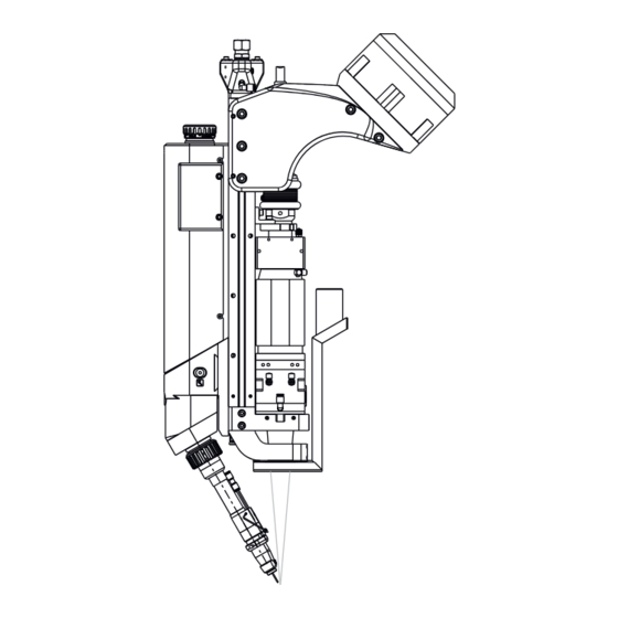
Page 29: Product Description
Product description Product descrip- tion WF 25i LaserHybrid 10 (15) (16) (17) (18) (10) (19) (20) (11) (21) (12) (13) (14) Item Name Crossjet exhaust air (must be connected to an extraction system) Crossjet supply Connection for optional pressure monitoring For optional pressure monitoring, a LaserHybrid hosepack with additional data line is required. - Page 30 Drive unit cover (10) Gas-test button Wire-return button * Wire-threading button * The wire-return and wire-threading buttons are located on the opposite side of the laser welding head. (11) Mounting plate Thickness 21 mm or 17.5 mm depending on application (12) LaserHybrid welding torch (13)
-
Page 31: Crossjet Versions
Crossjet ver- The Crossjet is available in 2 versions: sions Square design Round design Function and assembly is the same for both versions. Product descrip- tion SB 360i LaserHybrid (10) (11) (12) (13) (14) Back Front Item Name (+) Current socket with fine thread For connecting the power cable from the interconnecting hosepack Shielding gas connection socket SpeedNet connection... - Page 32 Welding torch cooling connection - coolant supply (blue) For connecting the coolant supply hose from the interconnecting hosep- SplitBox SB 360i LaserHybrid mount Welding torch connection (FSC) For connecting the LaserHybrid hosepack (10) Crossjet OUT connection (11) Crossjet OUT connection (12) Crossjet IN connection (13)
-
Page 33: Collision Protection
Collision Protection General The laser welding head is fitted with collision protection to protect the LaserHy- brid welding torch and the entire laser welding head. The collision protection works on the floating contact principle. Displacing the welding torch a certain amount will open the circuit (ring line) between the two inputs for the robot control. -
Page 34: Connection Specifications
Connection Specifications Connection spe- cifications (10) Item Name Crossjet extraction connection For connecting a hose as per the following data: inner diameter Di = 51 mm outer diameter Do = 57 mm max. length = 10 m Crossjet supply For connecting a hose as per the following data: inner diameter Di = 10 mm outer diameter Do = 14 mm p = 6 bar... -
Page 35: Required Compressed Air Quality
The hose connects the supply of radial air (3) with the radial air connec- tion (10). Crossjet gas nozzles supply For connecting a hose as per the following data: outer diameter Do = 4 mm The hose connects the Crossjet gas nozzles supply (4) with the Crossjet gas nozzles (7). -
Page 36: Compressed Air Diagram
Compressed air MHP LH = LaserHybrid hosepack diagram MHP LH SB 360i LaserHybrid WF 25i LaserHybrid 10 kW Item Name Compressed air supply line Solenoid valve Internal pressure measure- ment Pressure measurement option Radial air flow branch Crossjet gas nozzles branch Crossjet air supply lines con- nections Crossjet exhaust air... - Page 37 NOTE! The extraction unit for the extraction (9) must be suitable for the extraction of welding fume. NOTE! The "VALVE ON" signal for controlling the solenoid valve (2) is transmitted on bit 26 (away from 0).
-
Page 38: Pressure Monitoring In The Splitbox Sb 360I Laserhybrid
Pressure monit- The pressure is measured after the solenoid valve. oring in the If the pressure falls below 4.5 bar for longer than 2 seconds, then the "Power- SplitBox SB 360i source Ready" bit is withdrawn and the warning code 16835 (laser Crossjet air LaserHybrid pressure supply low) is output. -
Page 39: Commissioning
Commissioning... -
Page 41: General
General Safety WARNING! Work performed incorrectly can cause serious injury and damage to property. ▶ This setting work must only be carried out by trained and qualified person- nel. ▶ Observe the safety rules in the OI, in particular the "Safety Inspection" sec- tion. -
Page 42: Set Up Laserhybrid Welding System
Set Up LaserHy- WARNING! brid Welding System If a power source is connected to the grid during installation, there is a danger of serious injury and damage. Please read the information in the "Safety Rules" chapter in the Operating In- structions for the power source before starting for the first time. -
Page 43: Installing The Laser Welding Head On The Robot
Installing the Laser Welding Head on the Robot Connection op- tions on the ro- 90 mm 406,5 mm Example: Laser welding head with Trumpf laser optics NOTE! The IPG laser optics can only be mounted in the lower position and cannot be adjusted. -
Page 44: Mounting The Laser Welding Head On The Robot
Mounting the Mount the laser welding head to laser welding the robot according to the spe- head on the ro- cifications of the robot manufac- turer. -
Page 45: Installing And Connecting Splitbox Sb 360I Laserhybrid
Installing and Connecting SplitBox SB 360i Lase- rHybrid Mounting the Disconnect SplitBox SB 360i LaserHybrid and SplitBox mount SplitBox SB 360i Depending on the robot, mount an appropriate support for the SplitBox LaserHybrid on mount on the robot the robot IMPORTANT! Observe robot manufacturer's mounting instructions. - Page 46 Secure strain-relief device of the interconnecting hosepack using 2 Allen screws size 4 mm Open clamps (x2) Insert interconnecting hosepack into the clamps Close clamps Insert SplitBox SB 360i LaserHy- brid into the SplitBox mount as per the diagram Secure SplitBox into the SplitBox mount using 3 TX25 screws from above and 3 TX25 from below Tightening torque = 3.5 Nm...
-
Page 47: Preparing Compressed Air Hoses In The Laserhybrid Hosepack
Preparing com- CAUTION! pressed air hoses in the LaserHy- Danger from compressed air hoses that come loose! brid hosepack Personal injury, damage to property, and impaired welding results may result. ▶ Always prepare the compressed air hoses for supplying the Crossjet as de- scribed below. -
Page 48: Connecting The Splitbox Sb 360I Laserhybrid
SpeedNet (remote control) * gas purging connection Connect the LaserHybrid hosepack to the welding torch connection (Fronius System Connector) Close clamping lever Open the cover on the LaserHybrid hosepack Connect welding torch cooling connecting plug to the LaserHybrid... - Page 49 Connect the CrossJet air outlet as far as it will go Tighten the hexagonal nut of the compressed air hose manually on the SB 360i LaserHybrid Tighten the hexagonal nut using a 24 mm flat spanner 1 1/4–1 1/2 turns Loosen the hexagonal nut by ap- prox.
-
Page 50: Connecting Crossjet
Connecting Crossjet Connecting the Insert Crossjet exhaust air hose in- Crossjet to the opening Position fixing plate so that it is in a groove of the Crossjet exhaust air hose (x2—also on the opposite side) Secure fixing plate with 2 Allen screws, 3 mm (x2—also on the opposite side) - Page 51 IMPORTANT! Before connecting the compressed air hoses, prepare them as described un- der "Preparing compressed air hoses in the LaserHybrid hosepack" (see page47) When connecting the compressed air hoses, ensure that the cutting rings are present! Slide the compressed air hose into the screw connection body on the Crossjet as far as it will go Tighten the hexagonal nut of the...
-
Page 52: Connecting Laserhybrid Hosepack To Laser Welding Head
Connecting LaserHybrid Hosepack to Laser Weld- ing Head Connecting the IMPORTANT! When connecting the LaserHybrid hosepack, ensure that pins and LaserHybrid connections on the interface are not bent or damaged. hosepack to the Position the LaserHybrid hosepack to be as straight as possible. laser welding head Connect LaserHybrid hosepack... -
Page 53: Connecting/Changing Wirefeeding Hose To/On Laser Welding Head
Connect CrashBox cable Place cable in groove Connecting/ Insert wirefeeding hose into laser changing welding head Wirefeeding Hose to/on Laser Welding Head Press and hold locking button Insert the wirefeeding hose into the locking device as far as is needed to release the locking but- Release the locking button Keep pushing the wirefeeding hose until the locking device locks in... -
Page 54: Installing/Changing Wirefeed Rollers
Installing/Changing Wirefeed Rollers Installing/Chan- IMPORTANT! The wire electrode has to be pulled out in order to change the ging Wirefeed wirefeed roller. Rollers Disconnect external wirefeeding hose Swing the clamping stirrup open Remove the screwable shaft Remove the wirefeeder roller Remove the hexagon nut size 10 mm –... -
Page 55: Connecting The Ipg Laser Optics And Additional Extraction
Connecting the IPG laser optics and additional extraction Connecting the CAUTION! IPG laser optics Risk of damage to the laser welding head due to contamination from above. ▶ Observe the Operating Instructions, specifications, and safety instructions from the manufacturer of the laser optics ▶... - Page 56 Position the laser welding head so that the longitudinal axis of the laser welding head is outside the horizontal (> 90°) IMPORTANT! Do not clean connection areas using compressed air! Clean connection areas with a cloth. Remove the protective cover from the fiber optic cable connector Remove the protective cover from the fiber optic cable connection...
- Page 57 IMPORTANT! To seal the fiber optic cable, use only an adhesive tape that can be removed without leaving any residue, such as Tesa type 4172. Wrap the area around the connect- or of the fiber optic cable and the fiber optic cable connection sever- al times with adhesive tape and seal it cleanly Connect the optics cooling system,...
-
Page 58: Connecting The Ipg Additional Extraction
Connect the optics cooling return Position the laser welding head in the vertical line Connecting the Attach robot connection bracket IPG additional Push slot nut upwards, so that the extraction top hole of the slot nut is posi- tioned under the top hole of the robot connection bracket. - Page 59 For installation: The 3 shorter screws are one below the other; the 2 longer screws are oppos- ite. Insert the remaining 4 Allen screws, size 6 mm Fix the robot connection bracket in place using 5 Allen screws, size 6 Tightening torque = 24 Nm Attach one half of the clamp to the robot connection bracket...
-
Page 60: Connecting Other Laser Optics And Additional Extraction
Connecting other laser optics and additional ex- traction Connecting oth- CAUTION! er laser optics Risk of damage to the laser welding head due to contamination from above. ▶ Observe the Operating Instructions, specifications, and safety instructions from the manufacturer of the laser optics ▶... - Page 61 Position the laser welding head so that the longitudinal axis of the laser welding head is outside the horizontal (> 90°) Clean connection area using com- pressed air Remove the protective cover from the fiber optic cable connection Clean connector of the fiber optic cable using compressed air Remove the protective cover from the fiber optic cable connector...
- Page 62 IMPORTANT! When connecting the fiber optic cable, pay attention to the position of the register pin on the con- nector! Connect fiber optic cable: Press the button b) Pull back the rubber sleeve in the direction of the optics Connect the fiber optic cable connector Check whether the rubber sleeve is cleanly sealed all around the fiber...
-
Page 63: Connecting Extra Extraction
Connect the optics cooling supply (blue marking) Connect the optics cooling return Position the laser welding head in the vertical line Connecting Ex- Push the hose across the connec- tra Extraction tion Fix the hose in place with the hose clamp... - Page 64 Position bracket for robot connec- tion Push the slot nut up so that the top hole on the slot nut is posi- tioned below the top hole on the bracket for the robot connection. Fasten, but do not completely tighten, the slot nut and bracket for the robot connection using a short Allen screw size 6 mm Insert 2 x register pins...
- Page 65 For assembly: the 3 x shorter screws are located one below the other; the 2 x longer screws opposite each other. Insert the remaining 4 x Allen screws size 6 mm Fix the bracket for the robot con- nection in place using 5 x Allen screws size 6 mm Tightening torque = 24 Nm...
-
Page 66: Preparing Welding Torch
Preparing Welding Torch Available weld- The following welding torches are available for the laser welding head: ing torches MTB 500 LH/W/0°/L284 Standard welding torch for IPG laser optics, focal length F400 MTB 500 LH/W/0°/L228 Standard welding torch for Trumpf, Precitec and Highyag laser optics, focal length F300 LH 360A 0°... - Page 67 Insert the inner liner into the weld- ing torch from below Insert inner liner fully into the welding torch using the contact tip Apply the gas nozzle Tighten knurled nut...
-
Page 68: Equipping The Lh 360 Welding Torch
Equipping the Open knurled nut LH 360 welding torch Insert the inner liner into the weld- ing torch from below Insert inner liner fully into the welding torch using the contact tip... - Page 69 Position union nut via the contact Tighten the union nut Size 12 mm Tightening torque = 3 Nm Apply the gas nozzle Secure the gas nozzle with an Al- len screw, size 4 mm Fold bracket downwards Tighten knurled nut...
-
Page 70: Installing Hosepack On Robot
Installing Hosepack on Robot Placing the IMPORTANT! The optional LaserHybrid hosepack holder is not included in the hosepack on the scope of supply for the laser welding head. robot 44,0360,0099 (14) 10 x 5 Nm (10) 8 Nm (13) 2,9 Nm (11) (11) 27 Nm... - Page 71 Mounting HP LH xx Opening for fiber optic cable Mounting plate depending on Opening for extraction hose robot (with adapter insert) Item profile 10 50 x 50 mm, 2 Opening for LaserHybrid hosepack (42,1000,0112) (10) Opening for extraction hose Optional extension arm (11) Allen screw (44,0350,0254)
- Page 72 Installation Mount the mounting plate (1) to the robot arm according to the instructions of the robot manufacturer Cut the profile 10 50 x 50 mm (2) to length according to the robot arm Mount the profile 10 50 x 50 mm (2) using slot nuts and 4 hexagonal bolts, size 17 mm, to the mounting plate (1) Tightening torque = 10 Nm Remove Allen screw, size 3 mm (11), and disassemble the lower sheet metal...
-
Page 73: Threading The Wire Electrode
Threading the Wire Electrode Threading the IMPORTANT! Carefully deburr the end of the wire electrode before threading Wire Electrode the wire on it. Requirement: Wirefeeding hose connected Wire electrode threaded in wirefeeder reel Correct wirefeeder rollers and inlet nozzles present in laser welding head Close clamping stirrup Press the wire-threading button until the wire electrode comes out... -
Page 74: Setting Up Laser Welding Head
Setting up Laser Welding Head Stick out There are two different mounting plates for the laser welding head with Trumpf laser optics, depending on the application: The TCP must not be positioned at the laser focus. For high performance With the same adjustment path, guarantees a greater distance between laser focus and wire elec- trode tip... -
Page 75: Adjustable Axes
NOTE! When adjusting the spatial position of the welding torch, pay attention to the corresponding stick out depending on the mounting plate that is used. Welding torch Contact tip Stick out Mounting plate 17.5 mm: Stick out = 14 mm Mounting plate 21 mm: Stick out = 20 mm For all other laser optics, stick out = 20 mm. -
Page 76: Adjustment Devices On The Laser Welding Head
Adjustment The laser welding head is equipped with adjustment devices, which allow for pre- devices on the cise positioning in the x, y, and z coordinate axes: laser welding head Scale for the z axis Adjustment screw with gradu- ation for the y axis Adjustment range +/- 4.5 mm Allen screw size 5 mm ¼-turn corresponds to an ad-... -
Page 77: Adjusting The X Axis
Adjusting the x NOTE! axis The x and y axes are adjusted with the drive unit cover removed. ▶ After adjusting them, refit the drive unit cover. Loosen 2 Allen screws size 5 mm Adjust x axis using adjustment screw and Allen key size 5 mm: 1 turn corresponds to 1.0 mm After adjusting the x axis, re-tighten the 2 Allen screws size 5 mm (1) -
Page 78: Adjusting The Y Axis
Adjusting the y NOTE! axis The x and y axes are adjusted with the drive unit cover removed. ▶ After adjusting them, refit the drive unit cover. Loosen 2 Allen screws size 5 mm Adjust y axis using adjustment screw and Allen key size 5 mm: 1 turn corresponds to 1.0 mm After adjusting the y axis, re-tighten the 2 Allen screws size 5 mm (1) -
Page 79: Adjusting The Z Axis
Adjusting the z NOTE! axis The z axis is adjusted with the drive unit cover and the control box removed. ▶ After adjusting it, refit the control box and drive unit cover. Loosen 2 Allen screws size 5 mm Loosen 2 Allen screws size 5 mm Adjust z axis using adjustment screw and Allen key size 5 mm: 1 turn corresponds to 1.0 mm... -
Page 80: Creating Reference Program
Creating Reference Program Safety WARNING! Work performed incorrectly can cause serious injury and damage to property. ▶ This setting work must only be carried out by trained and qualified person- nel. ▶ Observe the safety rules in the OI, in particular the "Safety Inspection" sec- tion. - Page 81 Default setting for the parameter find- ing of the component to be welded: Using the robot, approach the gage so that the laser focus is in the cross hairs of the gage Using the robot, lower the laser welding head until the wire elec- trode touches the gage Use the x and y adjustment units on the laser welding head to posi-...
-
Page 82: Signal Sequence For Laserhybrid Welding
Signal Sequence for LaserHybrid Welding Safety WARNING! Work performed incorrectly can cause serious injury and damage to property. ▶ The welding process may only be programmed by trained personnel. ▶ Observe the safety rules in the OI, in particular the "Safety Inspection" sec- tion CAUTION! Risk of damage to the optical fiber due to the laser welding head being perpen-... - Page 83 LaserHybrid welding start position: Requirement: The laser must be ready for beam release. Set signal "Arc on" Wait for the current flow signal ("arc standing") Set signal "Laser on" Set signal "Start robot" LaserHybrid welding end position: Stop robot movement Reset signal "Laser on"...
-
Page 84: Measures Before Starting Welding
Measures before Starting Welding Measures before Check the coolant flow on the laser optics cooling system Starting Welding Check the coolant flow on the welding torch cooling system (visual inspection in the coolant tank of the cooling unit) Check whether a protective glass is present in the laser optics Check whether all covers are correctly mounted on the laser welding head Test CrossJet Test extraction... -
Page 85: Operation Recommendations For Laserhybrid Welding System
Operation Recommendations for LaserHybrid Welding System Recommenda- For smooth operation, the following items should always be available when using tions for the op- a LaserHybrid welding system: eration of a LaserHybrid LaserHybrid service station welding system Compressed-air gun supplied with 6 bar Mobile tool trolley with the following tools and spare parts: 20 x contact tips, for each diameter 10 x gas distributors... -
Page 87: Maintenance
Maintenance... -
Page 89: Overview Of The Laser Optics
Optics support, optics holder, robot connection bracket, and mounting material NOTE! The IPG Wobble optics can only be purchased from IPG. Optics support, optics holder, robot connection bracket, and mounting material for the IPG Wobble optics are available from Fronius under item number 4,101,349. -
Page 90: Trumpf, Precitec, And Highyag Laser Optics
Trumpf, Pre- citec, and Highy- ag laser optics TRUMPF PRECITEC HIGHYAG + 4,101,078 * + 4,100,714 * + 4,101,068 * 4x M5 x 16 mm 4x M5 x 16 mm 2x M5 x 16 mm 2x M5 x 25 mm 2x M4 x 12 mm 4x M5 x 16 mm 4x M5 x 12 mm... -
Page 91: Replacing The Welding Torch And Welding Torch Wearing Parts
Replacing the Welding Torch and Welding Torch Wearing Parts Safety CAUTION! Risk of burns due to the intensely heated welding torch during operation. ▶ The welding torch may only be cleaned, and its components checked, once it has cooled down. Welding torch MTB 500 LH/W/0°/L228 and MTB 500 LH/W/0°/L284 spare parts... -
Page 92: Replacing The Mtb 500 Lh Welding Torch
Replacing the Note: MTB 500 LH The numbering of the arrows in the diagrams may differ from the work steps. welding torch Remove the 2 Allen screws, size 2.5 Remove the 2 Allen screws, size 2.5 mm, on the opposite side Remove drive unit cover Open knurled nut Loosen union nut using torch... -
Page 93: Replacing The Lh 360 Welding Torch
Replacing the LH Note: 360 welding The numbering of the arrows in the diagrams may differ from the work steps. torch Remove the 2 Allen screws, size 2.5 Remove the 2 Allen screws, size 2.5 mm, on the opposite side Remove drive unit cover Open knurled nut... -
Page 94: Replacing Welding Torch Wearing Parts
Loosen union nut using torch wrench Remove the welding torch in a downwards direction 45,0200,1404 NOTE! Assembly of the welding torch only with torch connector and torque wrench, tightening torque = 18 +/- 2 Nm Replacing weld- MTB 500 LH/W/0°/L228 and MTB 500 LH/W/0°/L284: ing torch wear- ing parts... - Page 95 LH 360A 0°: IMPORTANT! Before assembly, clean gas distributor, thread of the union nut, and torch body.
-
Page 96: Replacing The Spatter Guard Plate And Extra Extraction
Replacing the Spatter Guard Plate and Extra Ex- traction Replacing the Remove 4 Allen screws IPG spatter Size 2.5 mm guard plate Remove spatter guard plate Install by performing the steps in the reverse order. Replacing the Remove the 4 Allen screws, size IPG additional 2.5 mm extraction... -
Page 97: Replacing The Spatter Guard Plate For Other Laser Optics
Replacing the Note: spatter guard The numbering of the arrows in the diagrams may differ from the work steps. plate for other laser optics Remove 2 Allen screws Size 2.5 mm Remove spatter guard plate Install by performing the steps in the reverse order Replacing the Note:... -
Page 98: Replacing The Ipg Laser Optics
Replacing the IPG laser optics Safety WARNING! Work performed incorrectly can cause serious injury and damage to property. ▶ This assembly work must only be carried out by trained and qualified person- nel. ▶ Observe the safety rules in the OI, in particular the "Safety Inspection" sec- tion. - Page 99 Position the laser welding head so that the longitudinal axis of the laser weld- ing head is outside the horizontal (> 90°) Disconnect the hose for additional extraction IMPORTANT! Only disconnect the coolant hose at the laser optics end, never from the fiber optic cable. Loosen the union nut, disconnect the cooling hose from the laser op- tics.
-
Page 100: Removing The Ipg Laser Optics
If present, dismantle additional ex- traction (see page 96) Remove 4 Allen screws Size 2.5 mm Remove spatter guard plate IMPORTANT! Ensure that the O-rings do not get lost when removing the Cross- jet. O-rings on the Crossjet Remove 4 Allen screws Size 3 mm Remove Crossjet Removing the... - Page 101 Loosen 2 hexagonal bolts Size 8 mm Remove 2 Allen screws Size 4 mm Push the mounting bracket "B" with the hexagonal bolts and the slot nuts in the profile away from the mounting "A" CAUTION! If dropped, the laser optics unit can be damaged to such an extent that it is rendered unusable.
-
Page 102: Installing The Ipg Laser Optics
Dismantle mount "A" from the laser optics Remove 4 screws Dismantle radial air flow from laser optics Ensure that the springs inserted on the underside are not lost. The springs will be required again for installation. Installing the IMPORTANT! When replacing the laser optics, ensure that the laser optics and IPG laser optics welding torch match in terms of the focal length. - Page 103 IMPORTANT! When inserting the new laser optics, pay attention to the cor- rect installation position: The connectors of the fiber optic cable, coolant hose, and protective glass tray must be accessible The push button must be on the Insert laser optics so that the springs on the bottom are in the grooves Press the back end of the laser op-...
- Page 104 Slightly screw mounting bracket "B" with 2 Allen screws, size 4 mm, to the mounting "A" Tighten the two 8 mm hexagonal bolts hand-tight Insert 4 Allen screws Lightly tighten Allen screws Size 4 mm Connect fiber optic cable to the laser optics see page from work step 4...
-
Page 105: Checking/Setting The Focus Of The Ipg Laser Optics
Use robot to position laser welding head so that the laser optics are at 90° an angle of 90° to the reference gage Connect radial air flow Check/set focus of the laser optics according to the following section Checking/ After replacing the IPG laser optics, the focus must be checked and adjusted if setting the focus necessary in order to even out possible optics tolerances. - Page 106 Setting the focus of the laser optics Loosen 4 Allen screws size 4 mm Set focus in y direction: Use hexagon socket grub screws (2) to adjust laser optics in y direc- tion Size 2.5 mm The installed springs absorb the +/- movement.
-
Page 107: Securing The Laser Optics
Securing the NOTE! laser optics In order to prevent tensioning of the laser optics on the laser welding head, the sequence of the following working steps must be complied with precisely! Bolt mounting bracket "B" to the mounting "A" using the 2 Allen screws, size 4 mm Tightening torque = 5.7 Nm Screw 2 hexagonal bolts, size 8... - Page 108 Fit spatter guard plate with 4 Allen screws Size 2.5 mm Fit robot connection bracket (see page 58, steps 1 - 8)
-
Page 109: Replacing Other Laser Optics
Replacing other laser optics Safety WARNING! Work performed incorrectly can cause serious injury and damage to property. ▶ This assembly work must only be carried out by trained and qualified person- nel. ▶ Observe the safety rules in the OI, in particular the "Safety Inspection" sec- tion. - Page 110 Remove 2 register pins: Apply and screw on extractor tool for register pins b) Knock the striking weight of the extractor tool backwards, thereby removing the register pins Remove robot connection bracket Position the laser welding head so that the longitudinal axis of the laser weld- ing head is outside the horizontal (>...
- Page 111 Disconnect radial air flow Remove 2 Allen screws size 2.5 mm Remove spatter guard plate Remove 2 Allen screws size 2.5 mm Remove additional extraction...
-
Page 112: Removing The Laser Optics
IMPORTANT! Ensure that the O-rings do not get lost when removing the Cross- jet. O-rings on the Crossjet Remove 4 Allen screws size 3 mm Remove Crossjet Removing the Remove 6 hexagon socket grub laser optics screws size 2.5 mm Remove 4 Allen screws size 4 mm Remove 2 Allen screws... - Page 113 Loosen 2 Allen screws size 4 mm CAUTION! If dropped, the laser optics unit can be damaged to such an extent that it is rendered unusable. ▶ Remove and handle the laser op- tics carefully. Push laser optics out of the guide and the bracket Remove laser optics IMPORTANT! When removing the laser optics, ensure that the springs inserted...
-
Page 114: Inserting The Laser Optics
Inserting the IMPORTANT! When replacing the laser optics, ensure that the laser optics and Laser Optics welding torch are compatible in terms of the focal length. CAUTION! Dropping the laser optics may lead to damage beyond repair. ▶ Insert and handle the laser optics carefully. - Page 115 Insert 4 x Allen screws Tighten the Allen screws slightly size 4 mm Fit fixing clamp Insert 2 x Allen screws Tighten the Allen screws slightly size 4 mm Connect the fiber optic cable on the laser optics see page 60, work step 2 onward...
- Page 116 Position the laser welding head via the robot so that the laser optics are at a 90° angle to the reference 90° gauge Connect radial air stream Connect coolant hose (1): to LaserHybrid hosepack to laser optics Connect coolant hose (2) to laser optics Check/adjust laser optics focus as described in the following section...
-
Page 117: Checking/Setting The Focus Of The Laser Optics
Checking/ After replacing Trumpf laser optics, the focus must be checked and adjusted if setting the focus necessary in order to even out possible optics tolerances. of the laser op- tics A low-power pilot laser is required for the adjustment work described. Checking the focus of the laser optics Depending on the mounting plate that is available, set the corresponding stick out of the wire electrode:... - Page 118 Set focus in y direction: Use hexagon socket grub screws (2) to adjust laser optics in y direc- tion size 2.5 mm The installed springs absorb the +/- movement. Tighten hexagon socket grub screws (1) and (3) size 2.5 mm Set focus in positive x direction: Loosen hexagon socket grub screws (1) by 2 turns Use the hexagon socket grub screws (3) to adjust laser optics in positive x dir-...
-
Page 119: Fixing The Laser Optics
Fixing the Laser NOTE! Optics To prevent the laser optics from warping on the laser head, ensure you perform the following work steps in the exact same sequence. Set up terminal Tighten 2 x Allen screws size 4 mm Tightening torque = 5.7 Nm Screw fixing clamp tight with 2 x Allen screws size 4 mm... -
Page 120: Final Tasks
Final tasks IMPORTANT! Check the focus of the laser optics before installing the Crossjet! IMPORTANT! Ensure that the O-rings are present when installing the Crossjet. O-rings on the Crossjet Install Crossjet with 4 Allen screws Size 3 mm Tightening torque = 2.5 Nm Install additional suction with 2 Al- len screws Size 2.5 mm... - Page 121 Attach robot connection bracket Push slot nut upwards, so that the top hole of the slot nut is posi- tioned under the top hole of the robot connection bracket. Use an Allen screw size 6 mm to lightly fix the slot nut and robot connection bracket Insert register pins (x2) Apply and screw on extractor tool...
- Page 122 Insert the remaining 4 Allen screws, size 6 mm Fix the robot connection bracket in place using 5 Allen screws size 6 Tightening torque = 24 Nm...
-
Page 123: Checking Position Of The Wire Electrode In Relation To The Laser Focus
Checking Position of the Wire Electrode in rela- tion to the Laser Focus Safety WARNING! Work performed incorrectly can cause serious injury and damage to property. ▶ This setting work must only be carried out by trained and qualified person- nel. - Page 124 Example: Refer- Switch off power source ence Program Change welding torch Application after After the welding torch has been changed and the wearing parts have been Welding Torch fitted: Change switch on power source Set the stick out to either 14 or 20 mm, depending on the application Upload the reference program and slowly move to the reference position on the adjusting gauge Thread the wire electrode until this is touching the adjusting gauge...
-
Page 125: Measures To Reduce Contamination Of The Optics
Measures to Reduce Contamination of the Optics Measures to Re- Crossjet and Extraction duce Contamin- ation of the Op- Please observe the values for the crossjet and extraction specified in these tics Operating Instructions. Switch on the crossjet and extraction at least five seconds before the start of welding. - Page 126 10. When using an automatic torch cleaning device: Switch on the crossjet and extraction during the cleaning process. Changing the Fiber Optic Cable 11. The laser welding head must be in a horizontal position when you are chan- ging the fiber optic cable so that no dust can fall into the optics from above. IMPORTANT! Clean with compressed air before changing.
-
Page 127: Appendix
Appendix... -
Page 129: Technical Data
1.0 - 1.6 mm Voltage rating (V-Peak) 141 V Cooling system Liquid cooling Coolant Original Fronius coolant Hosepack length 4.2 m / 7.5 m Lowest cooling capacity as per 1400 / 1500 W IEC 60974-2, depending on the hosepack length Coolant pressure min./max. -
Page 130: Sb 360I Lh
10 min/40°C (104°F) 60% ED* 450 A 100% ED* 360 A Maximum pressure of shielding gas 7 bar/101.53 psi Coolant Original Fronius Maximum pressure of coolant 5 bar/72.53 psi Protection class IP 20 Mark of conformity Dimensions l × w × h 560.4 x 334.93 x 113 mm...
Need help?
Do you have a question about the LaserHybrid WF 25i and is the answer not in the manual?
Questions and answers