
Related Manuals for Fronius Ignis 150 TIG


Summary of Contents for Fronius Ignis 150 TIG
- Page 1 Operating Instructions Ignis 150 TIG Ignis 180 TIG Operating Instructions 42,0426,0515,EN 001-13112023...
-
Page 3: Table Of Contents
Contents Safety rules Explanation of safety notices General Proper use Environmental conditions Obligations of the operator Obligations of personnel Mains connection Residual current protective device Protecting yourself and others Noise emission values Danger from toxic gases and vapours Danger from flying sparks Risks from mains current and welding current Meandering welding currents EMC Device Classifications... - Page 4 Average shielding gas consumption during MIG/MAG welding Average shielding gas consumption during TIG welding Technical data Explanation of the term "duty cycle" Ignis 150 TIG Ignis 180 TIG Ignis 180 TIG MV Overview with critical raw materials, year of production of the device...
-
Page 5: Safety Rules
Safety rules Explanation of DANGER! safety notices Indicates immediate danger. ▶ If not avoided, death or serious injury will result. WARNING! Indicates a potentially hazardous situation. ▶ If not avoided, death or serious injury may result. CAUTION! Indicates a situation where damage or injury could occur. ▶... -
Page 6: Proper Use
Proper use The device is to be used exclusively for its intended purpose. The device is intended solely for the welding processes specified on the rating plate. Any use above and beyond this purpose is deemed improper. The manufacturer shall not be held liable for any damage arising from such usage. Proper use includes: carefully reading and following all the instructions given in the operating in- structions... -
Page 7: Mains Connection
Before leaving the workplace, ensure that people or property cannot come to any harm in your absence. Mains connec- Devices with a higher rating may affect the energy quality of the mains due to tion their current consumption. This may affect a number device types in terms of: Connection restrictions Criteria with regard to the maximum permissible mains impedance Criteria with regard to the minimum short-circuit power requirement... -
Page 8: Noise Emission Values
Keep all persons, especially children, out of the working area while any devices are in operation or welding is in progress. If, however, there are people in the vi- cinity: Make them aware of all the dangers (risk of dazzling by the arc, injury from flying sparks, harmful welding fumes, noise, possible risks from mains cur- rent and welding current, etc.) Provide suitable protective equipment... -
Page 9: Danger From Flying Sparks
Flammable vapours (e.g. solvent fumes) should be kept away from the arc's radi- ation area. Close the shielding gas cylinder valve or main gas supply if no welding is taking place. Danger from fly- Flying sparks may cause fires or explosions. ing sparks Never weld close to flammable materials. -
Page 10: Meandering Welding Currents
Protection class I devices require a mains supply with ground conductor and a connector system with ground conductor contact for proper operation. Operation of the device on a mains supply without ground conductor and on a socket without ground conductor contact is only permitted if all national regula- tions for protective separation are observed. -
Page 11: Emc Measures
EMC device classification as per the rating plate or technical data. EMC measures In certain cases, even though a device complies with the standard limit values for emissions, it may affect the application area for which it was designed (e.g. when there is sensitive equipment at the same location, or if the site where the device is installed is close to either radio or television receivers). -
Page 12: Requirement For The Shielding Gas
During operation Ensure that all covers are closed and all side panels are fitted properly. Keep all covers and side panels closed. Welding wire emerging from the welding torch poses a high risk of injury (piercing of the hand, injuries to the face and eyes, etc.) Therefore, always keep the welding torch away from the body (devices with wirefeeder) and wear suitable protective goggles. -
Page 13: Danger From Shielding Gas Cylinders
Use filters if necessary. Danger from Shielding gas cylinders contain gas under pressure and can explode if damaged. shielding gas cyl- As the shielding gas cylinders are part of the welding equipment, they must be inders handled with the greatest of care. Protect shielding gas cylinders containing compressed gas from excessive heat, mechanical impact, slag, naked flames, sparks and arcs. -
Page 14: Safety Measures In Normal Operation
Before transporting the device, allow coolant to drain completely and detach the following components: Wirefeeder Wirespool Shielding gas cylinder After transporting the device, the device must be visually inspected for damage before commissioning. Any damage must be repaired by trained service techni- cians before commissioning the device. -
Page 15: Safety Inspection
(e.g. relevant product standards of the EN 60 974 series). Fronius International GmbH hereby declares that the device is compliant with Directive 2014/53/EU. The full text on the EU Declaration of Conformity can be found at the following address: http://www.fronius.com Devices marked with the CSA test mark satisfy the requirements of the relevant standards for Canada and the USA. -
Page 16: Data Protection
Data protection The user is responsible for the safekeeping of any changes made to the factory settings. The manufacturer accepts no liability for any deleted personal settings. Copyright Copyright of these operating instructions remains with the manufacturer. The text and illustrations are all technically correct at the time of printing. We reserve the right to make changes. -
Page 17: General
General Device concept The welding system has the following properties: Compact dimensions Robust plastic housing Extremely reliable even under harsh operating conditions Carrying strap for easy transport on construction sites, etc. Protected controls Current sockets with bayonet latch In conjunction with the digital resonance inverter, an electronic regulator adapts the welding system characteristic to suit the welding electrode during welding. -
Page 18: Application Areas
Do not use the functions described here until you have fully read and understood the following documents: These Operating Instructions All the Operating Instructions for the system components of the welding system, especially the safety rules Do not dispose of used devices with domestic waste. Dispose of them according to the safety rules. -
Page 19: Before Commissioning
Before commissioning Safety WARNING! Danger from incorrect operation and work that is not carried out properly. This can result in serious personal injury and damage to property. ▶ All the work and functions described in this document must only be carried out by technically trained and qualified personnel. -
Page 20: Generator-Powered Operation
Generator- The welding system is generator-compatible. powered opera- tion In order to dimension the required generator output, the maximum apparent power S of the welding system is required. 1max The maximum apparent power S of the welding system can be calculated as 1max follows: 1max... -
Page 21: Controls, Connections And Mechanical Components
Controls, connections and mechanical compon- ents Safety WARNING! Danger from incorrect operation and work that is not carried out properly. This can result in serious personal injury and damage to property. ▶ All the work and functions described in this document must only be carried out by technically trained and qualified personnel. -
Page 22: Ignis 150 Controls, Connections And Mechanical Components
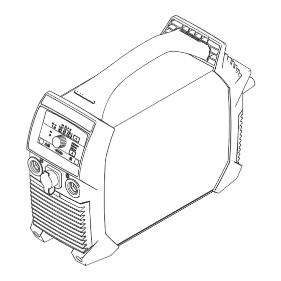
Ignis 150 con- trols, connec- tions and mech- anical compon- ents Control panel (-) current socket with bayonet latch TIG Multi Connector After connecting a remote control to the welding system ‘rc’ appears on the welding system display the welding current can only be adjusted using the remote control (+) current socket with bayonet latch Carrying strap... -
Page 23: Ignis 180 Controls, Connections And Mechanical Components
Ignis 180 con- trols, connec- tions and mech- anical compon- ents Control panel (-) current socket with bayonet latch TIG Multi Connector After connecting a remote control to the welding system ‘rc’ appears on the welding system display the welding current can only be adjusted using the remote control (+) current socket with bayonet latch Carrying strap... -
Page 24: Control Panel
Control panel STICK Setting value indicator shows which setting value is selected: Arc-force dynamic Welding current SoftStart / HotStart function Pulse welding Unit indicator shows the unit of the value that is currently being changed with the adjusting dial (7): Time (seconds) Percent Frequency (Hertz) - Page 25 Adjusting dial for continuous adjustment of the selected setting value (1) Status indicators display various operating modes of the welding system: lights up when the safety device for voltage reduction is activated (VRD devices only) Setup lights up in Setup mode Temperature lights up when the device is outside the permissible tem- perature range...
-
Page 26: Mma Welding
MMA welding Preparation CAUTION! Danger from electric shocks. As soon as the welding system is switched on, the electrode in the electrode holder is live. This can result in injury and damage to property. ▶ Ensure the electrode does not touch any persons or electrically conductive or earthed parts (the housing, etc.) -
Page 27: Mma Welding
MMA welding Use the welding process button to select one of the following processes: MMA welding - the MMA welding indicator lights up after selection MMA welding with Cel electrode - the MMA welding with Cel electrode indicator lights up after selection Press the setting value button until the welding current indicator lights up Adjust the welding current using the adjusting dial... -
Page 28: Arc-Force Dynamic
Turn the adjusting dial until the desired value is reached power source is ready for welding The maximum HotStart current is limited as follows: Ignis 150 to 160 A Ignis 180 to 200 A Examples (set welding current = 100 A): 100 % = 100 A starting current = function deactivated 80 %... -
Page 29: Pulse Welding
Turn the adjusting dial until the desired correction value is reached Welding system is ready for welding The maximum arc-force dynamic current is limited as follows: Ignis 150 to 180 A Ignis 180 to 220 A Examples: Arc-force dynamic = 0 arc-force dynamic deactivated soft, low-spatter arc Arc-force dynamic = 20... - Page 30 Adjustable parameters: F-P: Pulse frequency (1/F-P = time interval between two pulses) I-P: Pulse current SoftStart/HotStart Fixed parameters: I-G: Base current dcY: Duty cycle To use pulse welding: Press the setting value button until the pulse welding indicator lights up Turn the adjusting dial until the desired frequency value (Hz) is reached Welding system is ready for welding...
-
Page 31: Tig Modes
TIG modes Symbols and Pull back and hold the torch trigger their explana- tions Release the torch trigger forwards Push forward and hold the torch trigger Release the torch trigger backwards Adjustable parameters: GPo: Gas post-flow time I-S: Starting-current phase - the temperature is raised gently at low welding current, so that the filler metal can be positioned correctly I-E: Final current phase - to prevent crater cracks or cavitations I-1: Main current phase (welding-current phase) - uniform thermal input into... -
Page 32: 4-Step Mode
Raise the tungsten electrode => arc ignites Release torch trigger => end of welding 4-step mode See the description Parameters for TIG welding on page for details on how to activate 4-step mode. down 4-step mode with intermediate lowering I-2 Intermediate lowering means that the welder uses the torch trigger during the main current phase to lower the welding current to the specified reduced current I-2. -
Page 33: Tig Welding
TIG welding General NOTE! Do not use pure tungsten electrodes (colour-coded green) if the TIG welding process has been selected. NOTE! 2-step and 4-step welding is only possible if a welding torch with a TIG Multi Connector plug is used. Connecting the WARNING! gas cylinder... -
Page 34: Preparation
Preparation CAUTION! Danger from electric shocks. As soon as the welding system is switched on, the electrode in the welding torch is live. This can result in injury and damage to property. ▶ Ensure the electrode does not touch any persons or electrically conductive or earthed parts (the housing, etc.) If a welding torch is used without a TIG Multi Connector plug: In the Setup menu for the ‘operating mode’... -
Page 35: Setting The Gas Pressure
Setting the gas Welding torch with torch trigger (and pressure TIG Multi Connector plug): Press the torch trigger shielding gas flows Set the desired gas flow rate on the pressure regulator Release the torch trigger Welding torch with torch trigger (and TIG Multi Connector plug) TIG welding Select TIG welding with the welding process button... -
Page 36: Tig Comfort Stop
TIG Comfort To activate and set the TIG Comfort Stop function, see the description Para- Stop meters for TIG welding starting on page 42. Operating principle and use of the TIG Comfort Stop: Welding During welding, raise the welding torch the arc length is increased significantly Lower the welding torch the arc length is decreased significantly... -
Page 37: Pulse Welding
Gas pre-flow Gas post-flow DownSlope: The DownSlope time t is 0.5 seconds and cannot be adjusted. down Gas post-flow: The gas post-flow can be changed in the Setup menu via the "Gas post-flow time" parameter (Gas Post flow). Pulse welding Pulse welding is welding with a pulsing welding current. -
Page 38: Tacking Function
Fixed parameters: = UpSlope = DownSlope Down dcY = duty cycle I-G = base current To use pulse welding: Press the setting value button until the pulse welding indicator lights up Turn the adjusting dial until the desired frequency value (Hz) is reached Welding system is ready for welding Tacking function... - Page 39 The welding system controls the pulse frequency F-P, pulse current I-P, duty cycle dcY and base current I-G parameters according to the set main current I-1. The pulse current starts after the end of the starting-current phase I-S with the UpSlope phase t After the tAC time has elapsed, welding continues at a constant welding current, and any pulse parameters that may have been set are available.
-
Page 40: Welding Process Setup Menu
Welding process Setup menu Accessing the Use the Welding Process button to select the process whose Setup menu Setup parameters are to be changed: MMA welding MMA welding with Cel electrode TIG welding Press the Setting Value and Welding Process buttons at the same time The code for the first parameter in the Setup menu is dis- played on the control panel... - Page 41 Para- meter Description Range Unit Anti-stick When the anti-stick function is active, the arc is extinguished after 1.5 seconds in the event of a short circuit (sticking of the electrode) Factory setting: ON (activated) Start ramp To activate/deactivate grinding mode Factory setting: ON (activated) Break voltage (Voltage cut off) 25 - 90 Volts...
-
Page 42: Parameters For Tig Welding
Parameters for Para- TIG welding meter Description Range Unit Operating mode (trigger mode) Operation using welding torch without a torch trigger 2-step mode 4-step mode Factory setting: 2t Starting current (I-Start) 1 - 200 Percent This parameter is only available in 4-step mode (tri = 4t) Factory setting: 35% Reduced current... - Page 43 Para- meter Description Range Unit Comfort Stop Sensitivity 0.6 - 3.5 Volts This parameter is only available when the tri parameter is set to OFF Factory setting: 1.5 V For details, see TIG Comfort Stop starting at page Break voltage (Voltage cut off) 10 - 45 Volts Used to specify at which arc length the weld- ing process is to be completed.
-
Page 44: Setup Menu - Level 2
Setup menu - Level 2 Welding para- Paramet- meters in the Description Range Unit level 2 Setup Software version menu The full version number of the currently installed software is spread across a number of displays and can be retrieved by turning the adjusting dial. - Page 45 OFF (TP 180 A 220 A 180 MV only) 120 V* 15 A 85 A 130 A 16 A 95 A 140 A 20 A (TP 120 A 170 A 180 MV only) OFF (TP 120 A 170 A 180 MV only) * Depending on the triggering characteristic of the automatic circuit breaker, the full duty cycle of 40% cannot be achieved on 120 V grids (e.g.
-
Page 46: Care, Maintenance And Disposal
Care, maintenance and disposal Safety WARNING! Danger from incorrect operation and work that is not carried out properly. This can result in serious personal injury and damage to property. ▶ All the work and functions described in this document must only be carried out by technically trained and qualified personnel. -
Page 47: Maintenance Every 2 Months
Maintenance Clean air filter: every 2 months Disposal Dispose of in accordance with the applicable national and local regulations. -
Page 48: Troubleshooting
Troubleshooting Safety WARNING! Danger from incorrect operation and work that is not carried out properly. This can result in serious personal injury and damage to property. ▶ All the work and functions described in this document must only be carried out by technically trained and qualified personnel. - Page 49 It is also possible that several error numbers are present. These appear when turning the adjusting dial. Make a note of the error numbers shown on the display, and of the serial number and configuration of the welding system, and contact our after-sales service team with a detailed description of the error.
-
Page 50: No Function
Cause: Mains voltage too high Remedy: Pull out the mains plug immediately; ensure that the welding system is being operated on the correct mains voltage E36, E41, E45 Cause: Mains voltage outside tolerance or maximum load of grid is too low Remedy: Ensure that the welding system is being operated on the correct mains voltage;... -
Page 51: Faulty Operation
No welding current Device switched on, indicator for the selected welding process is lit, overtemper- ature indicator lit Cause: Duty cycle exceeded - device overloaded - fan running Remedy: Keep within duty cycle Cause: Thermostatic automatic circuit breaker has switched off the device Remedy: Wait until the welding system comes back on automatically at the end of the cooling phase (do not switch off the device - the fan will... - Page 52 Poor weld properties (severe spattering) Cause: Incorrect electrode polarity Remedy: Reverse electrode polarity (refer to manufacturer's instructions) Cause: Poor grounding (earthing) connection Remedy: Fasten earthing clamps directly to workpiece Cause: Setup parameters not ideal for selected welding process Remedy: Select the optimal settings in the Setup menu for the selected weld- ing process Tungsten electrode melting Tungsten inclusions in base metal during the ignition phase...
-
Page 53: Average Consumption Values During Welding
Average consumption values during welding Average wire Average wire electrode consumption at a wire speed of 5 m/min electrode con- 1.0 mm wire 1.2 mm wire 1.6 mm wire sumption during electrode dia- electrode dia- electrode dia- MIG/MAG weld- meter meter meter Steel wire electrode... -
Page 54: Technical Data
Look in the technical data for a ED value of 100% for the current ambient temperature. Reduce the output or amperage in line with this value so that the device can remain in use without observing a cooling phase. Ignis 150 TIG Mains voltage (U 1 x 230 V Max. effective primary current (I... -
Page 55: Ignis 180 Tig
Cos phi 0.99 32 mOhm Max. permitted mains impedance Z at PCC Recommended residual current circuit breaker Type B Welding current range (I ) rod electrode 10-150 A Welding current range (I ) TIG 10-150 A Welding current for MMA welding 10 min / 40 °C 35 % 60 % 100 %... -
Page 56: Ignis 180 Tig Mv
Mains voltage tolerance -20% / +15% Grid frequency 50/60 Hz Cos phi 0.99 285 mOhm Max. permitted mains impedance Z at PCC Recommended residual current circuit breaker Type B Welding current range (I ) rod electrode 10-180 A Welding current range (I ) TIG 10-220 A Welding current for MMA welding 10 min / 40 °C... - Page 57 Max. effective primary current 16 A 20 A 15 A 1eff Max. primary current (I 25 A 29 A 19 A 1max Max. apparent power (S 5.75 kVA 3.48 kVA 2.28 kVA 1max Mains fuse 16 A slow- 20 A slow- 15 A slow- blow blow...
-
Page 58: Overview With Critical Raw Materials, Year Of Production Of The Device
An overview of which critical raw materials are contained in this device can be terials, year of found at the following Internet address. production of www.fronius.com/en/about-fronius/sustainability. the device To calculate the year of production of the device: Each device is provided with a serial number...
Need help?
Do you have a question about the Ignis 150 TIG and is the answer not in the manual?
Questions and answers