Table of Contents
Advertisement
Quick Links
Advertisement
Table of Contents

Subscribe to Our Youtube Channel
Related Manuals for ACME STAGE PAR 600 ZOOM IP


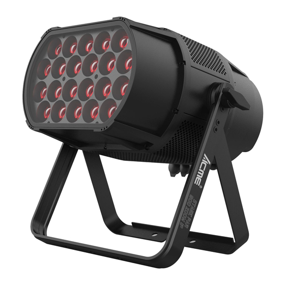
Summary of Contents for ACME STAGE PAR 600 ZOOM IP
-
Page 2: Table Of Contents
CONTENTS 1. Safety Instructions ..................2 2. Technical Specifications ................. 4 3. How To Set The Fixture .................. 6 3.1 Control Panel ................... 6 3.2. Fixture Installation .................. 7 3.3 Main Functions ..................10 3.4 Home Position Adjustment ..............17 4. -
Page 3: Safety Instructions
1. Safety Instructions Please read the instruction carefully which includes important information about the installation, usage and maintenance. WARNING Please keep this User Manual for future consultation. If you sell the unit to another user, be sure that they also receive this manual. Important: Damages caused by the disregard of this user manual are not subject to warranty. - Page 4 Avoid any flammable liquids, water or metal from entering the unit. Once it happens, cut off the mains power immediately. DO NOT operate in a dirty or dusty environment. DO clean the fixture regularly. DO NOT touch any wire during operation as there might be a hazard of electric shock. ...
-
Page 5: Technical Specifications
2. Technical Specifications Power Voltage: 100~240V 50/60Hz Power Consumption: 640W Light Source: 22x40W RGBW LED Beam Angle: 7°~35° Field Angle: 11°~57° Dimmer/Shutter: Smooth dimming from 0-100%; outstanding strobe effect with variable speed Control: DMX Channel: 5/7/9 channels Control Mode: DMX512, RDM, Primary/Secondary Mode Firmware Upgrade via DMX link Construction: Display: OLED display... - Page 6 Dimensions/Weight: 425x370x370mm, 15.4kgs(POWERCON VERSION) 16.7"x14.6"x14.6"in, 34lbs(POWERCON VERSION) 425x359x388mm, 16.5kgs(POWER CORD VERSION) 16.7"x14.1"x15.3"in, 36.4lbs(POWER CORD VERSION) Photometric Diagram:...
-
Page 7: How To Set The Fixture
3. How To Set The Fixture 3.1 Control Panel POWERCON VERSION POWER CORD VERSION 1. Display: To show the various menus and the selected function 2. Button: MENU To enter into move backward or leave the menu To go backward to move up in the menu DOWN To go forward to move down in the menu ENTER... -
Page 8: Fixture Installation
3.2. Fixture Installation DO install and operate by qualified operator. Fixture(s) should be installed in areas outside walking paths, seating areas, or away from areas were unauthorized personnel might reach the fixture by hand. NEVER stand directly below the fixture(s) when rigging, removing or servicing. Always ensure that the unit is firmly fixed to avoid vibration and slipping off during operation. - Page 9 Install the fixture by using clamp:...
- Page 10 Install the fixture by using omega bracket:...
-
Page 11: Main Functions
3.3 Main Functions Turn on the unit, press the MENU button into menu mode, and press the UP/DOWN button until the required function is shown on the monitor. Select the function by pressing the ENTER button. Use the UP/DOWN button to choose the submenu, press the ENTER button to store and automatically return to the last menu. - Page 13 DMX Setting To select DMX Setting, press the ENTER button to confirm, use the UP/DOWN button to select DMX Address or Channel Mode. DMX Address To select DMX Address, press the ENTER button to confirm. Use the UP/DOWN button to adjust the address from 001 to 508/506/504, press the ENTER button to store.
- Page 14 Constant Color To select Constant Color, press the ENTER button to confirm. Use the UP/DOWN button to select No or Yes, press the ENTER button to store. Press the MENU button back to the last menu or let the unit idle 30 seconds to exit menu mode. Dimmer Curve To select Dimmer Curve, press the ENTER button to confirm.
- Page 15 Show Program To select Show Program, press the ENTER button to confirm, use the UP/DOWN button to select Set Scene Totals, Edit Scene Color, Fade Time, Hold Time or Zoom. Set Scene Totals To select Set Scene Totals, press the ENTER button to confirm. Use the UP/DOWN button to adjust the value 0-50.
- Page 16 Manual Mode Select Manual Mode, press the ENTER button to confirm, use the UP/DOWN button to select Dimmer, Dimmer Fine, Strobe, Red, Green, Blue, White or Zoom. Use the UP/DOWN button to adjust the value 0-255, press the ENTER button to store. Press the MENU button back to the last menu or let the unit idle 30 seconds to exit menu mode.
- Page 17 Fixture Information Select Fixture Information, press the ENTER button to confirm, use the UP/DOWN button to select LED Temperature, Fixture Use Time, Light On time, Fan Speed or Firmware Version. LED Temperature Select LED Temperature, press the ENTER button to confirm, LED temperature will show on the display, press the MENU button to exit.
-
Page 18: Home Position Adjustment
RDM FUNCTIONS Select the MANUFACTURER menu to display the manufacturer of the fixture. Select the SOFTWARE VERSION menu and the program version number of the fixture will be displayed. Select the DMX START ADDRESS menu to change the DMX 512 address (001-512). Select the DEVICE MODEL DESCRIPTION menu to display the model of the fixture. -
Page 19: How To Control The Unit
4. How To Control The Unit You can operate the unit in two ways: 1. By primary/secondary built-in preprogram function 2. By DMX controller 4.1 DMX512 Controller If you use a universal DMX controller to control the units, you have to set DMX address from 1 to 512 so that the units can receive DMX signal. - Page 20 5 Channels mode: CHANNEL VALUE FUNCTION 000-255 0%100% GREEN 000-255 0%100% BLUE 000-255 0%100% WHITE 000-255 0%100% ZOOM 000-255 35°7° 7 Channels mode: CHANNEL VALUE FUNCTION DIMMER 000-255 0%100% STROBE 000-014 Open 015-042 Strobe from fast to slow 043-070 Pulse from fast to slow 071-078 Random Strobe 079-106...
- Page 21 000-255 0%100% ZOOM 000-255 35°7° 9 Channels mode: CHANNEL VALUE FUNCTION DIMMER 000-255 0%100% 000-255 DIMMER FINE STROBE 000-014 Open 015-042 Strobe from fast to slow 043-070 Pulse from fast to slow 071-078 Random Strobe 079-106 Burst from fast to slow 107-114 Random burst 115-142...
- Page 22 035-039 LEE 194–Surprise pink 040-044 LEE 181–Congo Blue 045-049 LEE 071–Tokyo Blue 050-054 LEE 120–Deep Blue 055-059 LEE 079–Just Blue 060-064 LEE 132–Medium Blue 065-069 LEE 200–Double CT Blue 070-074 LEE 161–Slate Blue 075-079 LEE 201–Full CT Blue 080-084 LEE 202–Half CT Blue 085-089 LEE 117–Steel Blue 090-094...
-
Page 23: Dmx512 Connection
4.3 DMX512 Connection 1. At last unit, the DMX cable has to be terminated with a terminator. Solder a 120-ohm 1/4W resistor between pin 2(DMX-) and pin 3(DMX+) into a 3-pin XLR-plug and plug it in the DMX-output of the last unit. 2. -
Page 24: Troubleshooting
5. Troubleshooting Following are a few common problems that may occur during operation. Here are some suggestions for troubleshooting: A. The unit does not work, no light and the fan does not work 1. Check the connected power. 2. Measure the voltage. 3. - Page 28 Innovation, Quality, Performance...
Need help?
Do you have a question about the STAGE PAR 600 ZOOM IP and is the answer not in the manual?
Questions and answers