Table of Contents
Advertisement
Quick Links
Advertisement
Table of Contents

Summary of Contents for ACME TV LIGHT PANEL 2000
-
Page 2: Table Of Contents
CONTENTS 1. Safety Introductions ..................2 2. Technical Specifications ................. 4 3. How To Set The Unit ..................6 3.1 Control Panel ................... 6 3.2 The Plate for Barn Door Installation ............7 3.3 Main Function ..................7 4. How To Control The Unit ................13 4.1 Primary/Secondary Function .............. -
Page 3: Safety Introductions
1. Safety Introductions Please read the instruction carefully which includes important information about the installation, usage and maintenance. WARNING Please keep this User Guide for future consultation. If you sell the unit to another user, be sure that they also receive this instruction manual. Important: Damages caused by the disregard of this user manual are not subject to warranty. - Page 4 DO NOT operate in a dirty or dusty environment. DO clean the fixture regularly. DO NOT touch any wire during operation as there might be a hazard of electric shock. Avoid entanglement of the power cord with other wires. ...
-
Page 5: Technical Specifications
Power In/Out: Power Connector in Protection Rating: IP20 Optical: CRI: VW≥94 CQS: VW≥94 TLCI: VW≥95 Features: With outstanding floodlight and soft light TV LIGHT PANEL 2000 is widely applied to photographic studio, TV station, conference room, shopping mall Access to buttery... - Page 6 Dimensions/Weight: 668x147.5x491.4mm, 13kgs 26.3"x5.8"x19.3"in, 28.7lbs 127.5 147.5 Photometric Diagram:...
-
Page 7: How To Set The Unit
3. How To Set The Unit 3.1 Control Panel 1. ETHERNET: Transfers fixture’s information to a main controller 2. DMX IN/OUT : For DMX512 link, use 5-pin XLR cable to link the unit to a DMX controller or the next unit and input/output DMX signal 3. -
Page 8: The Plate For Barn Door Installation
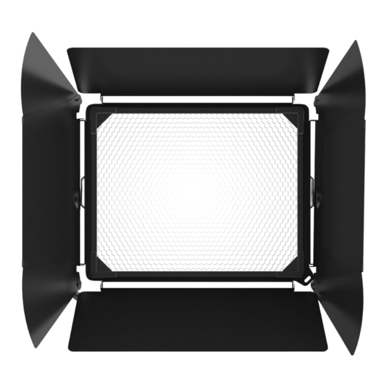
3.2 The Plate for Barn Door Installation At first, please push the barn door by hand. Screw Secondly, please put the Barn Door into the unit, to fasten the screws of the slot, then finish the barn door installation. 3.3 Main Function Turn on the unit, press the MENU button into menu mode, and press the UP/DOWN button until the required function is shown on the monitor. - Page 10 DMX Setting Select the DMX Setting, press the ENTER button to confirm. Use the UP and DOWN button to select DMX Address, Art-Net Setup or Channel Mode. DMX Address Select the DMX Address, press the ENTER button to confirm, the display will show the present address.
- Page 11 Optically Linear: The increase in light intensity appears to be linear as DMX value is increased. Square Law: Light intensity control is finer at low levels and coarser at high levels. Inverse Square Law: Light intensity control is coarser at low levels and finger at high levels. S-Curve: Light intensity control is finger at low levels and high levels and coarser at medium levels.
- Page 12 White Balance Select White Balance, press the ENTER button to confirm, the present mode will blink on the display, use the UP and DOWN button to select Warm White or Cool White and adjust the value from 50 to 100, press the ENTER button to store. Press the MENU button back to the last menu or idling 30 seconds to exit menu mode.
- Page 13 Manual Mode Select Manual Mode, press the ENTER button to confirm, the present mode will blink on the display, use the UP and DOWN button to select the Warm White or Cool White, press the ENTER button and use the UP and DOWN button to adjust the value from 0 to 255, press the ENTER button to store.
-
Page 14: How To Control The Unit
RDM FUNCTIONS Select the MANUFACTURER menu to display the manufacturer of the fixture. Select the SOFTWARE VERSION menu and the program version number of the fixture will be displayed. Select the DMX START ADDRESS menu to change the DMX 512 address (001-512). Select the DEVICE MODEL DESCRIPTION menu to display the model of the fixture. -
Page 15: Dmx Controller
4.2 DMX Controller If you use a universal DMX controller to control the units, you have to set DMX address from 1 to 512 so that the units can receive DMX signal. Press the MENU button to enter menu mode, select DMX Setting, press the ENTER button to confirm, use the UP/DOWN button to select DMX Address, press the ENTER button to confirm, the present address will blink in the display, use the UP/DOWN button to adjust the address from 001 to 512, press the ENTER button to store. - Page 16 2 Channel Mode: CHANNEL VALUE FUNCTIONS COLOR TEMPERATURE 000-255 5600K-3200K DIMMER 000-255 0%100% 3A Channel Mode: CHANNEL VALUE FUNCTIONS WW DIMMER 000-255 0%100% CW DIMMER 000-255 0%100% DIMMER 000-255 0%100% 3B Channel Mode: CHANNEL VALUE FUNCTIONS COLOR TEMPERATURE 000-255 5600K-3200K DIMMER 000-255 0%100%...
- Page 17 5 Channel Mode: CHANNEL VALUE FUNCTIONS WW DIMMER 000-255 0%100% CW DIMMER 000-255 0%100% STROBE 000-031 032-063 064-095 Strobe: Slow Fast 096-127 128-159 Strobe Pulse: Fast Slow 160-191 192-223 Random Strobe 224-255 DIMMER 000-255 0%100% 000-255 DIMMER FINE 6 Channel Mode: CHANNEL VALUE...
-
Page 18: Dmx512 Connections
4.4. DMX512 Connections 1. At last unit, the DMX cable has to be terminated with a terminator. Solder a 120-ohm 1/4W resistor between pin 2(DMX-) and pin 3(DMX+) into a 3-pin XLR-plug and plug it in the DMX-output of the last unit. 2. -
Page 19: Troubleshooting
5. Troubleshooting Following are a few common problems that may occur during operation. Here are some suggestions for troubleshooting: A. The unit does not work, no light and the fan does not work 1. Check the connected power. 2. Measure the voltage. 3. - Page 20 Innovation, Quality, Performance...


Need help?
Do you have a question about the TV LIGHT PANEL 2000 and is the answer not in the manual?
Questions and answers