Table of Contents

Related Manuals for Aplisens PC-29A


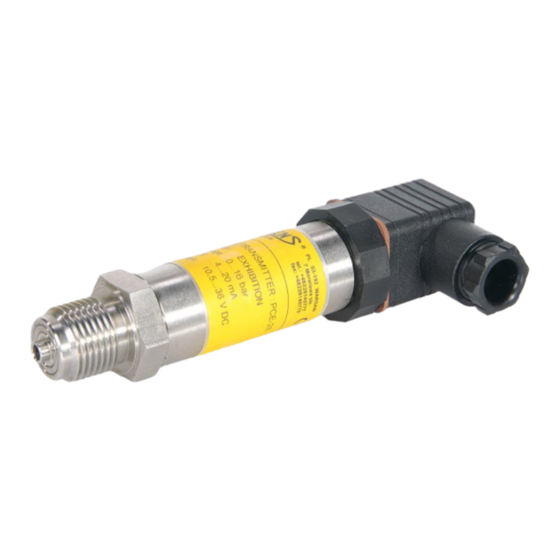
Summary of Contents for Aplisens PC-29A
- Page 1 EN.IO.PC.29.A.B Revision 01.A.001 MARCH 2022 USER’S MANUAL PRESSURE TRANSMITTERS PC-29A, PC-29B APLISENS S.A., 03-192 Warsaw, Morelowa 7 St. tel. +48 22 814 07 77; fax +48 22 814 07 78 www.aplisens.com, e-mail: export@aplisens.com...
- Page 2 PC-29A ID: 0033 0001 0000 0000 0000 0000 0001 38 https://www.aplisens.pl/ID/003300010000000000000000000138/ PC-29A (Exi) ID: 0033 0002 0000 0000 0000 0001 0001 55 https://www.aplisens.pl/ID/003300020000000000000001000155/ PC-29B ID: 0034 0001 0000 0000 0000 0000 0001 35 https://www.aplisens.pl/ID/003400010000000000000000000135...
- Page 3 − possible mechanical impacts, excessive shocks and vibration; − excessive temperature fluctuation; − water vapour condensation, dusting, icing. Changes made to the manufacturing of products may be introduced before the paper version of the manual is updated. The up-to-date manuals are available on the manufacturer’s website: www.aplisens.com.
-
Page 4: Table Of Contents
EN.IO.PC.29.A.B TABLE OF CONTENTS 1. INTRODUCTION ..................5 1.1. Purpose of the document ....................... 5 2. SAFETY ....................... 5 3. TRANSPORT AND STORAGE ..............5 3.1. Delivery check ........................5 3.2. Transport ..........................5 3.3. Storage ..........................5 4. GUARANTEE ....................6 5. -
Page 5: Introduction
The manual contains data, tips and general recommendations for safe installation and operation of the transmitters, as well as troubleshooting in case of possible failure. The manual does not cover explosion protection issues. Data of the PC-29A, PC-29B transmitters in intrinsically safe version acc. to IECEx and ATEX included... -
Page 6: Guarantee
The guarantee shall be repealed if the device is used against its intended use, failure to comply with user’s manual or interference with the structure of the device. IDENTIFICATION 5.1. Manufacturer’s address APLISENS S.A. 03-192 Warsaw Morelowa 7 St. Poland 5.2. -
Page 7: Installation
EN.IO.PC.29.A.B INSTALLATION 6.1. General recommendations In the case of the gaseous medium, it is recommended to install the transmitters above the measurement point so that the condensate may flow to the place where the measured pressure is taken, whereas in the case of the liquid medium or vapour, it should be installed below the place where the pressure is taken. -
Page 8: Electrical Connection
Internal electrical switching terminals are suitable for conductors with the cross-section from 0,5 to 2,5 mm 7.1.5. Cabling specification Aplisens S.A. recommends using two-wire screened twisted pair cable. The outer diameter of the cable shell from 8 to 10 mm (for cable gland PG-11) is recommended. 7.1.6. Equipotential bonding When using a cable in the screen, connect the screen on one side at the transmitters power supply point. -
Page 9: Overvoltage Protection
Type of transmitter Power supply Output signal 8 ÷ 16 V DC 0 ÷ 5 V PC-29A standard version 8 ÷ 16 V DC 0,5 ÷ 4,5 V 8 ÷ 16 V DC 0 ÷ 5 V PC-29A Exi version 8 ÷... -
Page 10: Start-Up
EN.IO.PC.29.A.B START-UP The base range and the basic unit can be read out from the transmitter’s nameplate (➔ Transmitter identification). Use the transmitter within the allowable pressure limits. Risk of injury due to component breakage after exceeding the maximum permitted operating pressure. MAINTENANCE 9.1. -
Page 11: Returns
EN.IO.PC.29.A.B 9.7. Returns In the following cases, the transmitter should be returned directly to the manufacturer: need for repair; need for factory calibration; replacement of improperly selected/shipped transmitter. 10. SCRAPPING, DISPOSAL Worn or damaged devices shall be scrapped in accordance with WEEE Directive (2012/19/EU) on waste electrical and electronic equipment or returned to the manufacturer. -
Page 12: Explosion-Proof Device Manual
EN IEC 60079-0:2018, EN 60079-11:2012, EN 50303:2000. IEC 60079-0:2017, IEC 60079-11:2011. Transmitters PC-29A, PC-29B, PR-29A, PR-29B, PC-29PA, PC-29PB may operate in areas where there is a risk of explosion, in accordance with the rating of the explosion protection design: ATEX:... - Page 13 Uo = Ui, Io = Ii, Po = Pi, Lo = 0.55 mH, Co = 0.3 F. Figure 1. Power supply PC-29A, PC-29PA, PR-29A, SG-25A with a “linear” characteristic - example. 3.2. Power supply PC-29B, PC-29PB, PR-29B, SG-25B: - for circuit of power supply - terminals 1 - 3: or red and black wires - for SG-25B Ui = 5,6 V DC, Ii=0,2 A, Pi = 0,56 W, for -40C ...
- Page 14 EN.IO.PC.29.A.B EN.IX.PC.PR.29.A.B Figure 2. Power supply PC-29B, PC-29PB, PR-29B, SG-25B with a “linear” characteristic - example. How to connect Exi transmitters The transmitter and other devices in the measuring loop should be connected in accordance with the intrinsic-safety and explosion-safety regulations and the conditions for use in dangerous areas. Fail- ure to observe the intrinsic-safety regulations can cause explosion and the resulting hazard to people.
- Page 15 EN.IO.PC.29.A.B EN.IX.PC.PR.29.A.B Figure 4. Connection of the transmitter with PK electrical connectors. Figure 5. Connection of the transmitter with PKD electrical connectors. Figure 6. Connection of the transmitter with SG electrical connectors. It is not allowed to repair or otherwise interfere with the transmitter’s electrical circuits in any way.
Need help?
Do you have a question about the PC-29A and is the answer not in the manual?
Questions and answers