Table of Contents
Advertisement
Quick Links
DTR.LI-24
(ENG)
APLISENS
MANUFACTURE OF PRESSURE TRANSMITTERS
AND CONTROL INSTRUMENTS
USER'S MANUAL
RAIL-MOUNTED
SMART TEMPERATURE TRANSMITTER
TYPE LI-24
Edition G
WARSAW MAY 2017
APLISENS S.A. 03-192 Warszawa, ul. Morelowa 7
tel. +48 22 814 07 77; fax +48 22 814 07 78
www.aplisens.pl, e-mail: aplisens@aplisens.pl
Advertisement
Table of Contents

Related Manuals for Aplisens LI-24


Summary of Contents for Aplisens LI-24
- Page 1 MANUFACTURE OF PRESSURE TRANSMITTERS AND CONTROL INSTRUMENTS USER’S MANUAL RAIL-MOUNTED SMART TEMPERATURE TRANSMITTER TYPE LI-24 Edition G WARSAW MAY 2017 APLISENS S.A. 03-192 Warszawa, ul. Morelowa 7 tel. +48 22 814 07 77; fax +48 22 814 07 78 www.aplisens.pl, e-mail: aplisens@aplisens.pl...
- Page 2 Symbols used Symbol Description Warning to proceed strictly in accordance with the information contained in the documentation in order to ensure the safety and full functionality of the device. Information particularly useful during installation and operation of the device. Information particularly useful during installation and operation of a type Ex device. Information on disposal of used equipment BASIC REQUIREMENTS AND SAFE USE - The manufacturer will not be liable for damage resulting from incorrect installation,...
- Page 3 Fig.4 The supplying principle with a source of rectangular characteristics........... 5 Fig.5. Connecting transmitter circuit – sensors connecting according to p.7..........6 Fig.6. Supply voltage in load resistance (Ro) function for LI-24 transmitter. Safe working area (grid) upper colour area..........................6 Fig.7.
-
Page 4: Introduction
This Manual is intended for users of smart temperature transmitters type LI-24 – in normal and intrinsic- safety versions. The data and information for the intrinsically safe LI-24 transmitter are given at point 5 „Use of the LI-24 transmitter in danger zones”. -
Page 5: Electronic System – Block Diagram
20mA SHIELD Fig.1. LI-24 transmitter – block diagram. 5. USE OF THE LI-24 TRANSMITTERS IN DANGER ZONES 5.1. List of norms. The transmitters are made in according to the requirements of the following standards: EN 60079-0:2012+A11:2013, EN 60079-11:2012, EN 50303:2000. -
Page 6: Permitted Intrinsic-Safety Parameters
DTR. LI-24(ENG) 5.3. Permitted intrinsic-safety parameters 5.3.1.Permitted sensors supply parameters (to 1, 2, 3, 4, 5 terminal sensors connection) Uo = 6V, Io = 0.1A, Co = 10μF, Lo = 1.5mH, Po = 0.5W 5.3.2. Permitted input parameters (to <DC>, <DC> terminals current loop) -
Page 7: Power Supply With The Rectangular Characteristics
“ib” protection level. 5.5. Assembly recommendations 5.5.1. General recommendations The LI-24 Transmitter connection should be made in accordance with fig. 5. The transmitter should be assembled at horizontal rail in the connecting boxes. Should be kept min distance 50mm between the terminals and the conducted circuit accessories galvanic separated. -
Page 8: Technical Parameters
- Power supply for intrinsic-safe versions - in accordance with p.5. Usup[V]-14V - Load resistance Ro = 0,023A - Resistance for communication (Hart) 250÷1100 Umax. Ex 1000 Ro[ ] Fig.6. Supply voltage in load resistance (Ro) function for LI-24 transmitter. Safe working area (grid) upper colour area. -
Page 9: Metrological Parameters
DTR. LI-24(ENG) List of current alarms Alarm Type Value of Alarm Current Alarm Type Value of Alarm Current Value of alarm current in NORMAL LOW 3,75 mA CUSTOM (value of alarm interval current is defined by user) 3,6 mA 23 mA... -
Page 10: Input With 2 Sensors
DTR. LI-24(ENG) ±0.8 ±0.035 Pt10 (W100=1.3910) -200÷1100 ±0.2 ±0.0070 Pt50 (W100=1.3910) -200÷1100 Analog output ±0.07 ±0.0035 Pt100 (W100=1.3910) -200÷1100 error: 0,05% ±0.05 ±0.00070 Pt500 (W100=1.3910) -200÷1100 GOST 6651- FSO(Full Scale -50 ÷ 200 ±0.2 ±0.0070 Cu50 (W100=1.426) Output) in all -50 ÷... -
Page 11: Normal Usage Conditions
DTR. LI-24(ENG) Voltage µV -10 … 100 ±6 <±0.001 Measuring range 1 As above Measuring range 2 -100 … 1000 ±50 <±0.001 ∆G – limiting error [K] or [%] calculated according to data (Tables 1 and 2). 0.05 [%] ∆G [K] = ∆p [K] + ∆tp... -
Page 12: Sensors Connection Options To Li-24 Transmitter
DTR. LI-24(ENG) SENSORS CONNECTION OPTIONS TO LI-24 TRANSMITTER. Fig.7. Sensors connection options to LI-24 transmitter. -
Page 13: Li-24 Transmitter Configuration
During work transmitter should be safe prior to entries. This prevents accidental or intentional changes configurational data. The protection function is accessible in KAP03 communicator, “Raport 2” or “LI-24 Configurator” software, as well as, in applying DD or DMT programs libraries. -
Page 14: Figures
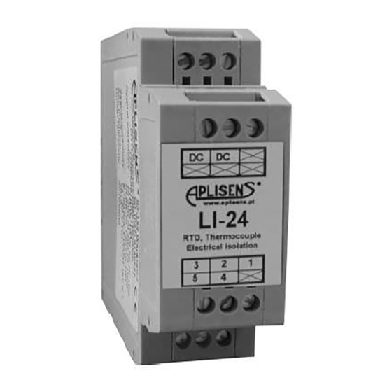
..II 1G Ex i IIC T4/T5 I M1 Ex i FTZÚ 08ATEX... OSTRZEŻENIE ! only for NIE PRZECIERAĆ NA SUCHO Ex version WARNING ! DON'T DRY WIPE Fig.9. Smart temperature transmitter type LI-24, dimensions, description.
Need help?
Do you have a question about the LI-24 and is the answer not in the manual?
Questions and answers