
Related Manuals for Aplisens AS


Summary of Contents for Aplisens AS
- Page 1 EN.IO.AS Revision 01.A.001 NOVEMBER 2021 USER’S MANUAL PRESSURE TRANSMITTER APLISENS S.A., 03-192 Warsaw, Morelowa 7 St. tel. +48 22 814 07 77; fax +48 22 814 07 78 www.aplisens.com, e-mail: export@aplisens.com...
- Page 2 The QR code or ID number identifies the transmitter and provides quick access to the following documentation on the manufacturer’s website: user’s manual, declarations of conformity and copies of certificates. ID: 0047 0001 0000 0000 0000 0000 0001 93 https://www.aplisens.pl/ID/004700010000000000000000000193...
- Page 3 Installation should be carried out by qualified staff having the required authorizations to install electrical and I&C equipment. The installer is responsible for performing the installation in accordance with manual as well as with the electromagnetic com- patibility and safety regulations and standards applicable to the type of installation.
- Page 4 EN.IO.AS SPIS TREŚCI 1. INTRODUCTION ..................5 2. SAFETY ....................... 5 3. TRANSPORT AND STORAGE ..............5 3.1. Delivery check ........................5 3.2. Transport ..........................5 3.3. Storage and use ........................5 4. GUARANTEE ....................5 5. IDENTIFICATION ..................6 5.1.
-
Page 5: Transport And Storage
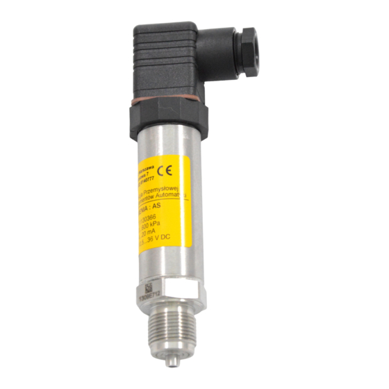
EN.IO.AS INTRODUCTION AS pressure transmitters are used to measure pressure where pressure overloads and pressure pul- sations may occur. Typical areas of application are: hydrophore sets, water mains, thermal prisons, district heating net- works, compressors, compressed air networks, compressors, compressed air systems. - Page 6 EN.IO.AS IDENTIFICATION 5.1. Manufacturer address APLISENS S.A. 03-192 Warsaw Morelowa 7 St Poland 5.2. Transmitter identification Depending on the version of the transmitter, the nameplates may differ in the amount of information and parameters. Table 1. Symbols appearing on the transmitter nameplate.
-
Page 7: Installation And Connection
EN.IO.AS INSTALLATION AND CONNECTION 6.1. General recommendation Run the signal line "twisted pair" or "twisted pair shielded" in case of high electromagnetic interference. Avoid running near power cables and large power consumers. The equipment used with the transmitters should be resistant to electromagnetic interference from the transmission line in accordance with compatibility requirements. -
Page 8: Power Supply
EN.IO.AS POWER SUPPLY Table 3. Transmitter supply voltage. 8…39 V DC Output signal 4…20 mA 2 wires 13…30 V DC Output signal 0…10 V DC 3 wires where: - voltage at the supply terminals of the 4…20 mA current loop [V]. - Page 9 EN.IO.AS 9.2.1. Diaphragm cleaning The only possible method of cleaning the transmitter membranes is to dissolve the sludge produced. Do not remove deposits and impurities from the transmitter diaphragms, which are formed during operation, mechanically using tools, since the diaphragms and the transmitter can be damaged.
Need help?
Do you have a question about the AS and is the answer not in the manual?
Questions and answers