Table of Contents
Advertisement
Quick Links
Advertisement
Table of Contents

Related Manuals for Aplisens PC-50


Summary of Contents for Aplisens PC-50
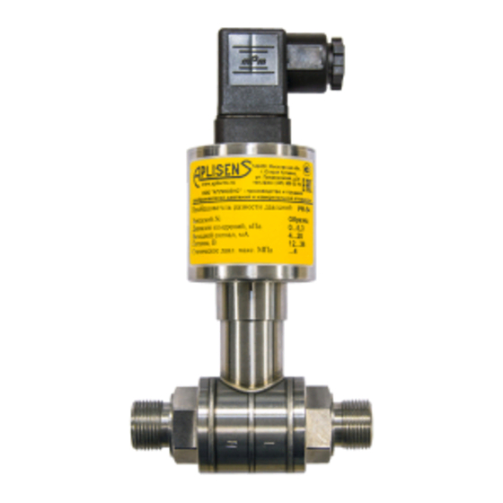
- Page 1 EN.IO.PC.PR.50 Revision 01.A.001 MARCH 2022 USER’S MANUAL PRESSURE TRANSMITTERS PC-50 DIFFERENTIAL PRESSURE TRANSMITTERS PR-50, PR-54, PRE-50G APLISENS S.A., 03-192 Warsaw, Morelowa 7 St. tel. +48 22 814 07 77; fax +48 22 814 07 78 www.aplisens.com, e-mail: export@aplisens.com...
- Page 2 The QR code or ID number identifies the transmitter and provides quick access to the following documentation on the manufacturer’s website: user’s manual, declarations of conformity and copies of certificates. PC-50 ID: 0049 0001 0000 0000 0000 0000 0001 87 https://www.aplisens.pl/ID/004900010000000000000000000187/...
- Page 3 − possible mechanical impacts, excessive shocks and vibration; − excessive temperature fluctuation; − water vapour condensation, dusting, icing. Changes made to the manufacturing of products may be introduced before the paper version of the manual is updated. The up-to-date manuals are available on the manufacturer’s website: www.aplisens.com.
-
Page 4: Table Of Contents
EN.IO.PC.PR.50 TABLE OF CONTENTS 1. INTRODUCTION ..................5 1.1. Purpose of the document .................... 5 2. SAFETY ....................... 5 3. TRANSPORT AND STORAGE ..............6 3.1. Delivery check ......................6 3.2. Transport ........................6 3.3. Storage........................6 4. GUARANTEE ....................6 5. -
Page 5: Introduction
INTRODUCTION 1.1. Purpose of the document The subject of manual are pressure transmitters PC-50, and differential pressure transmitters PR-50, PR-54, PRE-50G.The manual applies to the standard versions. The manual contains data, tips and general recommendations for safe installation and operation of the transmitters, as well as troubleshooting in case of possible failure. -
Page 6: Transport And Storage
3.1. Delivery check After receiving the delivery of the equipment, please refer to the general terms and conditions available on the manufacturer's website: https://aplisens.com/ogolne_warunki_umow.html. 3.2. Transport Transport of transmitters shall be carried out with the use of covered means of transport, in original packages with diaphragm provided with protection. -
Page 7: Identification
EN.IO.PC.PR.50 IDENTIFICATION 5.1. Manufacturer’s address APLISENS S.A. 03-192 Warsaw Morelowa 7 St. Poland 5.2. Transmitter identification Depending on the version of the transmitter, the nameplates may differ in the amount of information and parameters. Table 1. Symbols appearing on the transmitter's nameplate. -
Page 8: Installation
EN.IO.PC.PR.50 INSTALLATION 6.1. General recommendations It is recommended that in case of a gaseous medium, the transmitters should be installed above the measuring point so that condensate may flow to the point from which the meas- ured pressure is collected, while in case of liquid medium or steam, it should be installed below the point of pressure intake. -
Page 9: Electrical Connection
7.1.2. Cabling specification Aplisens S.A. recommends using two-wire screened twisted pair cable. The recommended cable outer diameter is 8-10 mm (PG-11 gland). Revision 01.A.001/2022.03... -
Page 10: Grounding
‘’-‘’ of power supply 3-wire transmission and output 39 V DC In addition, an external protective device can be used, e.g. UZ-2 system produced by APLISENS S.A. or others. 7.1.5. Shielding, equipotential bonding When using a cable in the screen, connect the screen on one side at the transmitter’s power supply point. -
Page 11: Transmitter Power Supply
Output signal Min. supply voltage Max. supply voltage 4…20 mA 10 V DC 36 V DC PRE-50G 2-wire transmission 0…20 mA PC-50 10 V DC 36 V DC PR-50 3-wire transmission 0…10 V PR-54 13 V DC 39 V DC 3-wire transmission 7.2.2. -
Page 12: Start-Up
EN.IO.PC.PR.50 START-UP The base range of the transmitter can be read out from its nameplate (➔ Transmitter identification). Use the transmitter within the allowable pressure limits. Risk of injury due to component break- age after exceeding the maximum permitted operating pressure. 8.1. -
Page 13: Maintenance
EN.IO.PC.PR.50 MAINTENANCE 9.1. Periodic inspections Periodic inspections shall be carried out in accordance with applicable standards. During the inspection, the condition of the pressure (absence of loosened elements and leaks) and electrical (check of con- nections reliability and condition of gaskets and glands) connectors, condition of separating diaphragms (tarnish, corrosion) and stability of fixing of the housing and mounting bracket (if used) shall be checked. -
Page 14: Scrapping, Disposal
EN.IO.PC.PR.50 10. SCRAPPING, DISPOSAL Worn or damaged devices shall be scrapped in accordance with WEEE Directive (2012/19/EU) on waste electrical and electronic equipment or returned to the manufacturer. 11. HISTORY OF REVISIONS Revision Document revision Description of changes DTR.PRE-50G(ENG)/07.2012 DTR.PRE-50G(ENG) Revision A/03.2014 Editorial changes. DTR.PR-54(ENG)/03.2016 New document edition.
Need help?
Do you have a question about the PC-50 and is the answer not in the manual?
Questions and answers