Aplisens PCE-28 User Manual
Pressure transmitters
Hide thumbs
Also See for PCE-28:
- User manual (40 pages) ,
- User manual (32 pages) ,
- User manual (26 pages)
Table of Contents
Advertisement
IO.PCE-28....PC-29.Exd
PCE-28, PCE-28.Smart, PCE-28 Ex Safety
PC-29A, PC-29B, PCE-28.Modbus
DIFFERENTIAL PRESSURE TRANSMITTERS
PRE-28, PRE-28.Smart, PRE-28 Ex Safety
PR-29A, PR-29B, PRE-28.Modbus
APLISENS S.A., 03-192 Warszawa, ul. Morelowa 7
www.aplisens.pl, e-mail:
MARCH 2019
USER'S MANUAL
PRESSURE TRANSMITTERS
Flameproof (Exd) version
tel. +48 22 814 07 77; fax +48 22 814 07 78
aplisens@aplisens.pl
04.A.004
Advertisement
Table of Contents

Related Manuals for Aplisens PCE-28


Summary of Contents for Aplisens PCE-28
- Page 1 PCE-28, PCE-28.Smart, PCE-28 Ex Safety PC-29A, PC-29B, PCE-28.Modbus DIFFERENTIAL PRESSURE TRANSMITTERS PRE-28, PRE-28.Smart, PRE-28 Ex Safety PR-29A, PR-29B, PRE-28.Modbus Flameproof (Exd) version APLISENS S.A., 03-192 Warszawa, ul. Morelowa 7 tel. +48 22 814 07 77; fax +48 22 814 07 78 www.aplisens.pl, e-mail: aplisens@aplisens.pl...
- Page 2 When using the device in potentially explosive areas, observe technical requirements specified in this manual and applicable local (national) regulations Changes in the manufacture of transmitters can overtake the update's paper documentation. Current manuals can be found on the manufacturer's website at www.aplisens.com...
-
Page 3: Table Of Contents
6.1. Intended use and functions ..................5 6.2. Construction and dimensions ..................5 6.3. Identification ........................ 8 7. USING OF PCE-28…PC-29 TRANSMITTERS IN HAZARDOUS AREAS ... 9 7.1. Exd versions in accordance with ATEX ............... 9 7.2. Exd versions in accordance with IECEx ..............9 7.3. - Page 4 Figure 4. PC(R)E-28, PC(R)E-28.Smart, PC(R)-29A, PC(R)-29B, PC(R)E-28.Modbus rating plate (example) ..................... 8 Figure 5. Transmitter installed in the hazard zones ..............9 Figure 6. Wiring diagram transmitters PCE-28, PRE-28, PCE-28 Ex Safety, PRE-28 Ex Safety ........................13 Figure 7. Wiring diagram transmitters PCE-28.Smart, PRE-28.Smart........13 Figure 8.
-
Page 5: Introduction
IO.PCE-28….PC-29.Exd INTRODUCTION The subject of this manual are: Pressure transmitters PCE-28; Pressure transmitters PCE-28 Ex Safety; Smart pressure transmitters PCE-28.Smart; Pressure transmitters PC-28E.Modbus; Pressure transmitters PC-29A, PC-29B; Differential pressure transmitters PRE-28; Differential pressure transmitters PRE-28 Ex Safety;... -
Page 6: Safety Procedures
Product Certificate, which is also a warranty card; b) Declaration of Conformity; c) Copy of the certificate (on request); d) User Manual ref. No. IO.PCE-28…PC-29(ENG). Items b), c) and d) are available on the website www.aplisens.com TRANSPORT AND STORAGE 4.1. -
Page 7: Warranty
IO.PCE-28….PC-29.Exd WARRANTY Manufacturer warrants to the conditions specified in the Product Certificate which is also a guarantee card. Warranty is in full force under the condition of using the devices properly along with the purpose determined in the manual. CONSTRUCTION 6.1. -
Page 8: Figure 1. Pressure Transmitter Pce-28, Pce-28 Ex Safety, Pce-28.Smart, Pc-29A, Pc
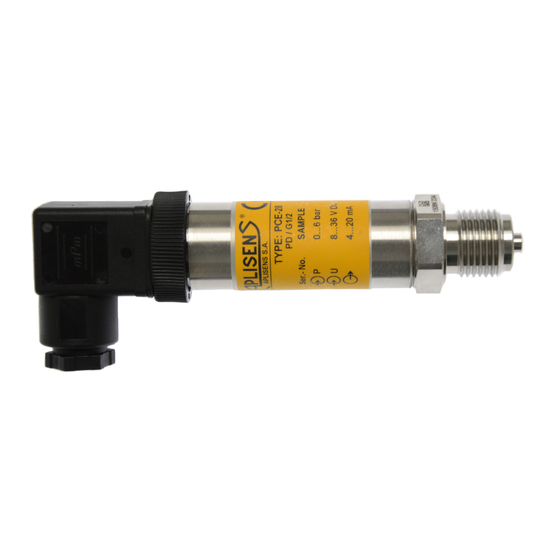
IO.PCE-28….PC-29.Exd Figure 1. Pressure transmitter PCE-28, PCE-28 Ex Safety, PCE-28.Smart, PC-29A, PC-29B, PCE-28.Modbus. Dimensions Figure 2. Pressure transmitter PRE-28, PRE-28 Ex Safety PRE-28.Smart, PR-29A, PR-29B, PRE-28.Modbus. Dimensions 04.A.004... -
Page 9: Figure 3. Electrical Connections Of The Transmitters Pc(R)E-28, Pc(R)E-28 Ex Safety
IO.PCE-28….PC-29.Exd Transmitter can be equipped with: “M” process connection, thread M20x1,5; “P” process connection, thread M20x1,5 and 12 hole; “CM30x2” process connection, thread M30x2 with flush diaphragm; “G 1/2” process connection, thread G1/2’’ and 4 hole;... -
Page 10: Identification
IO.PCE-28….PC-29.Exd 6.3. Identification Transmitters are provided with a rating plate containing: 1. Manufacturer name and/or logotype; 2. CE marking; 3. Number of notified body; 4. Product code; 5. Type of transmitter: „Pressure transmitter” or „Differential pressure transmitter”; 6. Transmitter type designation;... -
Page 11: Using Of Pce-28
EN 60079-0:2012 + A11:2013, EN 60079-1: 2014, EN 60079-31:2014. 7.2. Exd versions in accordance with IECEx The transmitters PCE-28, PCE-28 Ex Safety, PCE-28.Smart, PC-29A, PC-29B, PCE- 28.Modbus and pressure transmitters PRE-28, PRE-28 Ex Safety, PRE -28.Smart, PR- 29A, PR-29B, PRE-28.Modbus may operate in potentially explosive areas and are... -
Page 12: Electrostatic Hazards
When selecting assembly components, it may be helpful to refer to information on connection elements, reduction elements, sockets, valves, reduction clamps and signal tubes provided by APLISENS. Further data may be found in the "Valves and fitting accessories" catalogue card. -
Page 13: Electrical Connections
It is also beneficial to use noise filters on the primary side of transformers, power supplies for transmitters and apparatus operating with them 9.1. How to connect different types of transmitters PCE-28, PRE-28, PCE-28 Ex Safety, PRE-28 Ex Safety connection „FL(…)” connection „SGM(…)” connection Red wire... -
Page 14: How To Connect Transmitters In Potentially Explosive Areas
IO.PCE-28….PC-29.Exd PCE-28.Smart, PRE-28.Smart connection „FL(…)” connection „SGM(…)” connection Red wire Red wire (+) Black wire Black wire Green wire (cable shield) PCE-28.Modbus, PRE-28.Modbus connection „FL(…)” connection „SGM(…)” connection Red wire Red wire Black wire Black wire Blue wire (VA) Blue wire... -
Page 15: Figure 6. Wiring Diagram Transmitters Pce-28, Pre-28, Pce-28 Ex Safety, Pre-28 Ex
IO.PCE-28….PC-29.Exd Transmitters should be supplied in accordance with the following diagrams Figure 6. Wiring diagram transmitters PCE-28, PRE-28, PCE-28 Ex Safety, PRE-28 Ex Safety Figure 7. Wiring diagram transmitters PCE-28.Smart, PRE-28.Smart. Figure 8. Wiring diagram transmitters PC-29A, PR-29A, PC-29B, PR-29B... -
Page 16: Figure 9. Pce-28.Modbus, Pre-28.Mobdus Electrical Connection
IO.PCE-28….PC-29.Exd Figure 9. PCE-28.Modbus, PRE-28.Mobdus electrical connection 04.A.004... -
Page 17: Grounding
10.1. Electrical parameters Transmitter Power supply Signal output 8÷30V DC 4÷20mA PCE-28, PRE-28, 10,5÷30V DC 4÷20mA PCE-28 Ex Safety, PRE-28 Ex Safety 7,5÷30V DC 4÷20mA + Hart PCE-28.Smart, PRE-28.Smart. 4÷28V DC MODBUS RTU PCE-28.Modbus, PRE-28.Modbus. 7,5...16V DC 0,5...4,5V 1...5V 8...16V DC PC-29A, PR-29A 0...5V... -
Page 18: Electromagnetic Compatibility, Emissions
IO.PCE-28….PC-29.Exd Electromagnetic fields (radiated interferences): PN-EN 61000-4-3 80…2000MHz - 10V/m; …2700MHz - 1V/m; Criterion A; Fast electrical transient conditions (Burst): PN-EN 61000-4-4 ± 2kV supply lines; ± 1kV signal lines; Criterion B; Surges: PN-EN 61000-4-5 ± 0,5kV (±1kV) signal lines - enclosure; ± 1kV (±2kV) supply lines - enclosure; Criterion B;... -
Page 19: Inspections. Spare Parts
IO.PCE-28….PC-29.Exd INSPECTIONS. SPARE PARTS 11.1. Periodic inspections During inspection, the connectors should be checked for loose connections and leaks, the electrical connectors should be checked with regard to tightness and the state of the housing, gaskets, cable glands, and the diaphragm seals should be checked for tarnishing and corrosion.
Need help?
Do you have a question about the PCE-28 and is the answer not in the manual?
Questions and answers