Aplisens APC-2000ALW User Manual
Smart pressure transmitter; smart differential pressure transmitter; smart level transmitter
Hide thumbs
Also See for APC-2000ALW:
- User manual (35 pages) ,
- Manual (21 pages) ,
- User manual (29 pages)
Table of Contents
Advertisement
DTR.APC.APR.ALW.03
(ENG)
APLISENS
MANUFACTURE OF PRESSURE TRANSMITTERS
AND CONTROL INSTRUMENTS
USER'S MANUAL
SMART PRESSURE TRANSMITTER
type: APC-2000ALW
SMART DIFFERENTIAL PRESSURE TRANSMITTER
type: APR-2000ALW, APR-2200ALW, APR-200GALW
SMART LEVEL PROBE
type: APR-2000YALW
SMART LEVEL TRANSMITTER APC-2000ALW/L...
Edition A1
WARSAW MARCH 2013
APLISENS S. A. 03-192 Warszawa, ul. Morelowa 7
tel. +48 22 814 07 77; fax +48 22 814 07 78
www.aplisens.pl, e-mail: aplisens@aplisens.pl
Advertisement
Table of Contents

Related Manuals for Aplisens APC-2000ALW


Summary of Contents for Aplisens APC-2000ALW
- Page 1 APR-2000ALW, APR-2200ALW, APR-200GALW SMART LEVEL PROBE type: APR-2000YALW SMART LEVEL TRANSMITTER APC-2000ALW/L… Edition A1 WARSAW MARCH 2013 APLISENS S. A. 03-192 Warszawa, ul. Morelowa 7 tel. +48 22 814 07 77; fax +48 22 814 07 78 www.aplisens.pl, e-mail: aplisens@aplisens.pl...
- Page 2 Installation of intrinsically safe versions should be performed with particular care, in accordance with the regulations and standards applicable to that type of installation Changes in the production of transmitters may precede a paper updating for the user - the current user manuals are available at http. www.aplisens.pl...
-
Page 3: Table Of Contents
APPLICATIONS AND MAIN FEATURES....................17 IDENTIFYING MARKS. ORDERING PROCEDURE ................18 TECHNICAL DATA..........................18 5.1. APC..., APR...- C ........................18 OMMON PARAMETERS 5.2. APC-2000ALW M .............. 20 EASUREMENT RANGES AND METROLOGICAL PARAMETERS 5.3. APR-2000ALW, APR-2200ALW M ........21 EASUREMENT RANGES AND METROLOGICAL PARAMETERS 5.4. - Page 4 DTR.APC.APR.ALW.03 (ENG) . 18. APR–2000YALW ................57 SMART LEVEL PROBE FOR PRESSURE TANKS . 19. T APC...,APR................58 HE EXPLOSION PROOF JOINTS OF TRANSMITTERS . 20. H APC...,APR.................. 58 OW TO LEAD THE CASING OF TRANSMITTERS .
-
Page 5: Appendix Exd.02
APR-2000YALW/XX LEVEL PROBE, Exd VERSION 1. Introduction 1.1. This “Appendix Exd.02” applies to transmitters of types APC-2000ALW/XX, APR-2000ALW/XX, APR-2200ALW/XX and APR-2000YALW/XX in Exd versions only, marked on the rating plate as shown in p.3 and denoted Exd in the Product Certificate. - Page 6 Appendix Exd0.2. (ENG) User can find them b), c), d) at www.aplisens.pl 5. Power supply and exploitation of transmitters. 5.1. The transmitter connecting should be made after introduction with present instruction content. Electrically transmitter should be connected according to scheme at p.6 Appendix Exd. Transmitter...
- Page 7 Damage estimation and repair possibility may be assessed by the manufacturer or another authorized party only. In danger zone don’t unscrew transmitter covers and don’t change the display position or its back lighting. Appendix Exd0.2 6. The electrical connection way of transmitters series: APC-2000ALW/XX, APR-2000ALW/XX, APR-2200ALW/XX APR-2000YALW/XX flameproof version...
- Page 8 DTR.APC.APR.ALW.03 (ENG) Table 1. permitted cable glands Type Producer Screw Feature Other marking No of certificate 501/423 HAWKE M20x1,5 Exd IIC dimension OS, O, A Baseefa 06 ATEX 0056X 501/421 HAWKE M20x1,5 Exd IIC dimension OS, O, A Baseefa 06 ATEX 0056X ICG 623 HAWKE M20x1,5...
-
Page 9: Appendix Exi
DTR.APC.APR.ALW.03 (ENG) Appendix Exi II. APPENDIX Exi APC–2000ALW PRESSURE TRANSMITTER, 1453 APR–2000ALW, APR–2200ALW, APR–2000GALW DIFFERENTIAL PRESSURE TRANSMITTERS, APR–2000YALW LEVEL PROBE, APC–2000ALW/L LEVEL TANSMITTER Ex VERSION 1. Introduction 1.1. This “Appendix Exi” applies to transmitters of types APC–2000ALW, APR–2000ALW, APR–2200ALW, APR–2000GALW, APC–2000ALW/L and APR–2000YALW in Ex versions only, marked on the rating plate as shown in 2.2 and denoted Ex in the Product Certificate. - Page 10 − User’s Manual numbered: DTR.APC.APR.ALW.03 with Appendix Exi. (ENG) User can find them at www.aplisens.pl Appendix Exi 5. Permitted input parameters (based on data from the FTZÚ 08 ATEX 0020X certificate, and certification documentation). The transmitters should be powered via the associated power feeding and measurement devices provided with the relevant intrinsic-safe certificates.
- Page 11 Jumper ≥ 250Ω a Ex power supply TEST TEST SIGNAL see p.5. 240 Ω Aplisens KAP-03Ex Communicator DE F G HI @ %& S TU V WX To measure the current in the transmitter without disconnecting the signalling circuit, connect a milliammeter to control sockets TEST+, TEST-.
- Page 12 DTR.APC.APR.ALW.03 (ENG) Special conditions for safe use - Version of transmitter with surge arrester, marked on the plate "SC, SA", does not meet the requirements of Section 10.3 of the EN 60079-11:2012 (500Vrms). This must be taken into account when installing the equipment. Transmitter electrical installation should be realised with engineering standard requirements.
-
Page 13: Iii. Appendix Mid
APPLICATIONS ACCORDANCE IN EN12405-1 STANDARD INTRODUCTION 1.1. The " MID Appendix " applies only to the APC-2000ALW absolute / relative transmitters applications where they are as instruments for use in/as measuring devices (MI-002 gas) in accordance with the PN-EN 12405-1 + A2:2010 standard harmonized to Measuring Instruments Directive (MID) 2004/22, and the OIML R140: 2007 recommendations. - Page 14 DTR.APC.APR.ALW.03 (ENG) Appendix MID List of completeness. Together with APC-2000ALW transmitters user receives: a) Product Certificate which is also a warranty, b) Declaration of Conformity - on request c) User's Manual d) Copies of certificates - on request, e) calibration certificate - on request Items: b, c, d can be found at: www.aplisens.pl...
- Page 15 Transmitters in the MID version are equipped with one of the following types of Aplisens pressure ports: M, P, G1/2 G1/4, GP, R1/2, 1/2NPT (see p.5.2.4.). Pressure connection type, which designation given is the type of transmitter, the purchaser should agree with the manufacturer.
- Page 16 The manufacturer recommends a vertical mount transmitters APC-2000ALW during the pressure measurements in MID applications. 7. APC-2000ALW in MID application. Electronic display. Electronic indicating device (display), built-in the APC-2000ALW transmitters, are not controlled metrologically and as such can not be used for clearing in accordance with EN12405-1 + A2: 2010...
- Page 17 Access “spec MID locking” protects against unauthorized interference to transmitters from a Hart system. APC-2000ALW Series transmitters manufacturer is using with a plastic seal in its MID realization. Change of the "spec MID locking”...
- Page 18 Transmitter verify in the workplace should make a worker who is trained in the handling of measuring electrical installations in explosive environments. 11. APC-2000ALW in MID application. Repair, calibration Transmitters repair should be performed by the manufacturer, or the manufacturer's authorized repair shops.
-
Page 19: Features, Installation And Maintenance Of Transmitters
) in conjunction with Exi or Exd Appendix. (ENG 1.5. The pressure transmitters: APC-2000ALW, APR-2000ALW in realization for sea uses are complied with Det Norske Veritas (DNV) Rules for Classification of Ships, High Speed & Light Craft and Det Norske Veritas' Offshore Standards. -
Page 20: Identifying Marks. Ordering Procedure
Communication with the transmitter to verify its configuration parameters is performed using a Hart signal. For that, you can use the KAP-03 communicator for pressure transmitters or APLISENS modems: SH05 or Hart / USB / Bluetooth, or another any Hart modem and your PC, and Report2 program Resistance for communication (HART) min 240Ω... - Page 21 DTR.APC.APR.ALW.03 (ENG) 5.1.2. APC..., APR... Permitted environmental conditions Operating temperature range -40°C ÷ 85°C (for PED version in accordance with p. 5.2.3.) Operating temperature range for intrinsic-safe versions in accordance with Appendix Exi Operating temperature range for flame-proof versions in accordance with Appendix Exd Operating temperature range for MID versions in accordance with Appendix MID.
-
Page 22: Apc-2000Alw Measurement Ranges And Metrological Parameters
DTR.APC.APR.ALW.03 (ENG) 5.2. APC-2000ALW Measurement ranges and metrological parameters. 5.2.1. APC..., Measurement ranges Nominal measuring range Overpressure limit ° Minimum set range Rangeability (FSO) (without hysteresis) 0...1000bar (0...100MPa) 10bar (1MPa) 100:1 1200bar (120MPa) 0...300bar (0...30MPa) 3bar (300kPa) 100:1 450bar (45MPa) 0...160bar... -
Page 23: Apr-2000Alw, Apr-2200Alw Measurement Ranges And Metrological Parameters
DTR.APC.APR.ALW.03 (ENG) R1/2-type connector with R1/2 tread, available for PED version CG1/2-type connector with G1/2 tread and flush diaphragm, available for PED version other connection types by arrangement. 5.3. APR-2000ALW, APR-2200ALW Measurement ranges and metrological parameters. 5.3.1. APR-2000ALW, Measurement ranges Nominal measuring range Overpressure Static pressure... -
Page 24: Apr-2000Galw, Measurement Ranges And Metrological Parameters
0,1 % / 10bar * zeroing in static pressure conditions with zero differential pressure eliminate this error. Medium density range – up to 1,1 g/cm 3 – (standard version) – over 1,1 g/cm 3 – (special version by arrangement with APLISENS... -
Page 25: Apc-2000Alw/L.... M Easurement Ranges And Metrological Parameters
Possibility of zer shift 0...18m H 0...9m H 0...2m H 5.6.2. APC–2000ALW/L…level transmitter. Metrological parameters. Accuracy ± 0,16% (FSO) for the APC-2000ALW nominal range ≤ Long term stability accuracy / 2 years Error due to supply voltage changes ± 0,002%(FSO)/1V Thermal error ±... -
Page 26: Apc ... Apr ... E Nvironmental Parameters
DTR.APC.APR.ALW.03 (ENG) 5.7. APC … APR … Environmental parameters 5.7.1. Electromagnetic Compatibility (EMC), 5.7.3. Climatic Immunity Immunity Criterion according to EN 61326-1,2 Temperature: EN 60068-2-1, EN 60068-2-2 Electrostatic Discharge (ESD): hot: T = 55 C, RH = max 55% EN 61000-4-2 cold: T = -25 level 3, contact ±6kV... -
Page 27: Construction
DTR.APC.APR.ALW.03 (ENG) 6. CONSTRUCTION 6.1. Principle of measurement. Electronic system construction The electrical signal from the sensor which is proportional to the pressure is sent to a digital analog input and converted to a digital signal. The digital signal is transmitted through optoelectronic galvanic barrier to conditioning module. -
Page 28: Place Of Installation
DTR.APC.APR.ALW.03 (ENG) 7. PLACE OF INSTALLATION 7.1. General recommendations 7.1.1. The smart pressure transmitter and differential pressure transmitter can be installed both indoors and outdoors. It is recommended that transmitters intended for outdoor use be placed in a box or under cover. 7.1.2. -
Page 29: Mechanical Vibration, Shocks. Corrosive Media
DTR.APC.APR.ALW.03 (ENG) 7.4. Mechanical Vibration, shocks. Corrosive Media. 7.4.1. Transmitters should correctly work with vibrations with amplitudes to 1,6 mm and accelerations to 4g. If strong vibrations are carried via the pressure line and disturb of measuring, use should be made of elastic pulse lines or transmitters with a remote diaphragm seal. -
Page 30: Apr-2000Yalw. Installation And Connections
The transmitter sensor is immersed in measured medium. The sensor can be hung on the power cable by using a APLISENS SG handle , but especially in the case of long cables, or if are opportunities of hooking protruding elements when the cable is pulling up, it is recommended that the sensor suspended on a steel rope using the sensor lug. -
Page 31: Electrical Connections For Apc
(see the table, column 3). Also external protective devices may be used, e.g. the UZ-2 Aplisens system, or others. When the transmission lines are long, it is advantageous to use one protective device near the transmitter (or inside it), and another near entry points to other devices used in conjunction with it. -
Page 32: Configuration And Calibration
The transmitter may also be calibrated, by taking readings with the input pressure controlled using a standard device. This process and zero-point adjustment are called “Calibration”. 10.2.4. Configuration and Calibration of the transmitter are carried out using an Aplisens KAP communicator, certain Hart communicators or a PC with Hart/RS232 converter and Aplisens “Raport” software. - Page 33 DTR.APC.APR.ALW.03 (ENG) 10.2.5. TRANSMITTER CONFIGURATION WITH USING ITS BUTTONS AND LOCAL MENU 10.2.5.1. Local menu - structure. EXIT→ [↓][roll down] [↑][roll up] → ◙ [set] PVZERO→ [↓][roll down] [↑][roll up] → ◙ [set] BACK BACK PVZERO PVZERO → ◙ [set] SETLRV→...
- Page 34 DTR.APC.APR.ALW.03 (ENG) TRANSF→ [↓][roll down] [↑][roll up] ◙ [set] BACK BACK LINEAR SQUARE SQRT SPECIA SPECIA SQRT SQUARE LINEAR %SQRT→ [↓][roll down] [↑][roll up] ◙ [set] PERCEN CURREN LCD2VR→ [↓][roll down] [↑][roll up] → ◙ [set] BACK BACK PRESS CPU_T USER SENS_T SENS_T...
- Page 35 DTR.APC.APR.ALW.03 (ENG) EXIT (First announcement which will see after inclusion of Menu Local. If you will confirm this option, you will go out from Local Menu and you will come back to continue of measuring) PV ZERO_________ BACK (Return to Local Menu. If you will confirm this option, you will come back to main tree of Local Menu) PV ZERO (Pressure zeroing.
- Page 36 DTR.APC.APR.ALW.03 (ENG) UNIT____________ BACK (Return to Local Menu. If you will confirm this option, you will come back to main tree of Local Menu) (Confirm one of the following characteristics across longer press button ◙. After parameter confirmation transmitter will confirm the party of command by the "DONE") IN_H2O IN_HG FT_H2O...
- Page 37 DTR.APC.APR.ALW.03 (ENG) % SQRT______ (Square root characteristic cut-of point setting) BACK (Return to Local Menu. If you will confirm this option, you will come back to main tree of Local Menu) (Confirm one of the following percent value across longer press button ◙. After parameter confirmation transmitter will confirm the party of command by the "DONE") 0.0 % 0.2 %...
- Page 38 DTR.APC.APR.ALW.03 (ENG) LCD2 DP_________ (The process variable point position on LCD2) BACK (Return to Local Menu. If you will confirm this option, you will come back to main tree of Local Menu) (Confirm one of the following option across longer press button ◙. After parameter confirmation transmitter will confirm the party of command by the "DONE") XXXXX•...
- Page 39 DTR.APC.APR.ALW.03 (ENG) 10.2.5.3. LCD display configuration - installed till 2010. Changes of the display options in local MENU are possible using buttons or remote way using communicator, or the PC software. If it is necessary the display switching off is also possible. The display switching of function is possible with using communicator or PC software only.
- Page 40 DTR.APC.APR.ALW.03 (ENG) 10.2.5.3. Setting up a local LCD display - the display in accordance with EN 12405-1 (MID) installed since 2011. There 3 main displays are visible • LCD1 – the current or guidance percent preset range display. In accordance with display configuration the current value in 4 -20 mA current loop, or percent guidance preset range is possible to display.
- Page 41 DTR.APC.APR.ALW.03 (ENG) EXIT return from the local Menu to the normal operation of the transmitter UNIT menu process variable units. Options: IN_H2O inches of water at a temperature of 68 ° Fahrenheit IN_HG inches of mercury at a temperature of 68 ° Fahrenheit FT_H2O foot of water a temperature of 68 °...
- Page 42 DTR.APC.APR.ALW.03 (ENG) LCD2DP setting the decimal point position on LCD2. Options: XXXXX· XXXX·X XXX·XX XX·XXX X·XXXX In a situation where the value provided to display on the display LCD2 can not be displayed properly due to the position of the decimal point, this is indicated by displaying the four flashing dots •...
- Page 43 DTR.APC.APR.ALW.03 (ENG) 10.2.8. Configuration of the APR-2200ALW transmitters to measure the level, density of liquid and phase boundary Configuration of the APR-2200ALW transmitters to measure the level of liquid in a tank. Configuration of the APR-2200ALW transmitters to measure density of liquids.
- Page 44 DTR.APC.APR.ALW.03 (ENG)
-
Page 45: Inspections And Spare Parts
DTR.APC.APR.ALW.03 (ENG) 10.2.9. Configuration of the APR-2200YALW smart level probes Mechanical installation On the flange of the tank Upper equalization hole Lower equalization hole Diaphragm seal unit 10.3. Alarms. Exceeding the transmitter correct operation limits or non functioning of some its components are signaled by alarms. -
Page 46: Other Services
DTR.APC.APR.ALW.03 (ENG) 11.2. Other services If the transmitters are installed in a location where they may be exposed to mechanical damage, excess pressure, hydraulic impulses or excess voltage, or the diaphragm may be in danger from sedimentation, crystallization or erosion, inspections should be carried out as required. Where it is found that the signal in the transmission line is absent or its value is incorrect, a check should be made on the line and its terminal connections. -
Page 47: Figures
DTR.APC.APR.ALW.03 (ENG) 15. FIGURES. Memory Power supply/ Sensing Input Output Noise Converter measurement module circuit circuit filter system Modem Load resistance Ω min.250 Fig. 1. APC...,APR... transmitters – block diagram. Communicator or modem electrical connections to transmitter measuring lines. For successful communication with transmitter the resistance in measuring loop, behind connected device to communication, should be higher than 250Ω. - Page 48 DTR.APC.APR.ALW.03 (ENG) RS 232 BELL RAPORT JUMPER Current loop 4÷20 mA Ω SIGNAL To measure the transmitter current without disconnecting the measuring loop, connect a milliammeter to control terminals <Test -> and <Test +>. @%& Fig.2b. The link of transmitter and communicator or modem to <SIGNAL+> <SIGNAL-> transmitter terminals in case of the resistance in current loop is higher than 250Ω.
-
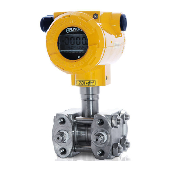
Page 49: Fig. 3. Apc-2000Alw Smart Pressure Transmitter
After communication jumper should came back at its place. 2 x M6 The electrical The electronic terminals side circuits and display side PD electrical connector, IP65 DIN 43650 connector with PG-11 ∅6...∅9 Cable Earthing Lock preventing rotation terminal of the casing Fig. 3. APC-2000ALW smart pressure transmitter... -
Page 50: Fig. 4. Apc
DTR.APC.APR.ALW.03 (ENG) ±180 with 90 pitch unscrew the Configuration display cover buttons and casing display screws Move the electronic unit from transmitter casing, take up the upper part of the casing with display from the catch and revolve its to left or to right to the display setting at needed position. -
Page 51: Fig. 5. M-Type Connector With M20X1.5 Thread
DTR.APC.APR.ALW.03 (ENG) Fig.5a. M-type connector Fig.5b. Socket for M-type connector with M20x1.5 thread min.15 diaphragm seal Fig.6a. P-type connector Fig.6b. Socket for P-type connector with M20x1.5 thread min.15 diaphragm seal Fig.7a. CM30x2-type connector Fig.7c. Socket for Fig.7b. Socket for with flush diaphragm CM30x2-type connector CM30x2-type with M30x2 thread,... -
Page 52: Fig. 8. Process Connections G1/2" And G1
DTR.APC.APR.ALW.03 (ENG) 24,5 -0.5 14,5 min. Fig.8b. Socket for G1/2-type connector. Fig.8a. G1/2 -type connector with G1/2" thread, 21,5 -0,2 min.10,5 Sealing: teflon 21,2 x 24,4 x 1,7 O-ring 15x2 20,5 -0,1 27-6kt. Fig.8c. CG1/2 -type connector Fig.8d. Socket for with flush diaphragm CG1/2 - type connector with G1/2"... -
Page 53: Fig . 9. Apr-2000Alw Differential Pressure Transmitter With Ctype Vented Covers
DTR.APC.APR.ALW.03 (ENG) 2 x M6 The electrical The electronic terminals side circuits and display side 4 x M10 PD electrical connector, IP65 DIN 43650 connector with PG-11 Lock preventing Earthing terminal ∅6...∅9 Cable rotation of the casing Fig. 9. APR-2000ALW differential pressure transmitter with C type vented covers. S-T type tube flanged diaphragm seal... -
Page 54: Fig. 11. Example: How To Install The Apr-2200Alw Transmitters With Remote Diaphragm
4 holes 34,5 ∅ Assembly Kit ("Mounting bracket 25" made by APLISENS) for fitting differential pressure transmitters ∅ with P-type connector on a 25 pipe see catalogue cards "Fitting accessories". Fig. 11. Example: how to install the APR-2200ALW transmitters with remote diaphragm. -
Page 55: Fig. 12. Example: How To Install The Apr-2000Alw Transmitter On A Vertical Or Horizontal Pipe
DTR.APC.APR.ALW.03 (ENG) 161,5 Fastener C2 for fitting differential pressure transmitters with C-type connection to a 2” pipe or to a wall. see catalogue cards „Fitting accessories” Fig. 12. Example: how to install the APR-2000ALW transmitter on a vertical or horizontal pipe. Fastener C2 for fitting differential pressure transmitters with a valve manifold to a 2”... -
Page 56: Fig. 14. Apr-2200Alw Differential Pressure Transmitter With Two Remote Diaphragm Seals (Examples)
DTR.APC.APR.ALW.03 (ENG) S-TK type tube flanged remote diaphragm seal S-PK type flush flanged remote diaphragm seal S-CompK P-type or S-CompK GP-type or ∅51 S-CompK -type remote diaphragm seal S-DINK type remote diaphragm seal ∅50, ∅65, ∅80 Fig. 14. APR-2200ALW differential pressure transmitter with two remote diaphragm seals (examples) Fig. -
Page 57: Fig . 16. Example : How To Install The Apc..., Apr... Transmitter
DTR.APC.APR.ALW.03 (ENG) Fastening on a pipe Fastening to a wall Fig. 16. Example: how to install the APC..., APR... transmitter... -
Page 58: Fig. 17. Apr-2000Galw Smart Differential Pressure Transmitter For Low Ranges
DTR.APC.APR.ALW.03 (ENG) Fig. a. Fig. b. The electrical The electronic terminals side circuits and display side Fig. c. ∅51 ∅51 Adapter for valve manifold or ∅51 steel impulse lines SW27 1/4 NPT 2holes ∅12 M8x10 (G1/2") ∅14 ∅6 Adapter M20x1.5/ ∅12 Weidable impulse Valve manifold... - Page 59 DTR.APC.APR.ALW.03 (ENG) ∅138 ∅160 ∅200 ∅80 Stanless steel or aluminium tube up to 6m long (by order) ∅80 Fig. 18. APR–2000YALW smart level probe for pressure tanks.
- Page 60 DTR.APC.APR.ALW.03 (ENG) for M20x1,5 for 1/2NPT MINIMUM WIDTH OF JOINT AND MAXIMUM GAP FOR GROUP IIC ENCLOSURES width of joint diameter minimum quantity (min. real) N° according to of joint PN-EN 60079-1:2004(U) ∅ ∅ width of joint min.12,5; +0,05 12,55 3,05 0,15 -0,05...
- Page 61 DTR.APC.APR.ALW.03 (ENG) Mounting bracket PC ∅7 4 holes (spacing of holes 38x38mm) ∅25 ∅25 ∅60 APC-2000ALW/LSG-25.S APC-2000ALW/LSG-25 ∅55 Submersible sensor Submersible sensor (sensor specification according to (sensor specification according to APC-2000ALW/LSG-25S-Titan data sheet for SGE-25S) data sheet for SGE-25) Submersible sensor...
- Page 62 DTR.APC.APR.ALW.03 (ENG) Mounting bracket PC ∅7 4 holes (spacing of holes 38x38mm) ∅25 ∅25 APC-2000ALW/LM APC-2000ALW/LSP Transmtter with M type sensor Transmtter with SP type diaphragm seal Fig. 22. APC–2000ALW/LM & APC–2000ALW/LSP smart pressure or level transmitters...
- Page 63 DTR.APC.APR.ALW.03 (ENG) M20x1,5 or G1/2" Moving M20x1,5 or G1/2" Moving Impulse line 10 MPa max. Marerials: R35 - (SO) 304ss - (S) Ordering code: Impulse line - (S) or (SO) /M20x1,5 or G1/2" M20x1,5 G1/2" Siphon tube ∅8 25 MPa ∅14 max.
Need help?
Do you have a question about the APC-2000ALW and is the answer not in the manual?
Questions and answers