Advertisement
Quick Links
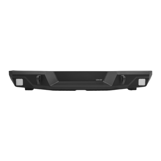
SLIM REAR BUMPER
07-17 JEEP WRANGLER JK
RBJK-12
TOOLS
REQUIRED
- 16, 18mm Socket
- Breaker Bar
WARNINGS/CAUTIONS BEFORE STARTING INSTALLATION
Before you install this kit —
instructions, warnings, cautions, and notes contained in
this installation instruction guide. Consult your vehicle
owner's manual for proper disconnection of electrical and
lifting of vehicle if required for installation of this product.
This install may require some technical skills and
knowledge of basic mechanical work. If you do not feel that
you are capable of performing this install please take this
product to a trained professional.
After reading this guide please contact us with any
questions or concerns before installing product.
Customer Service: 855-680-9595
DV8 Offroad is not responsible for any bodily injury or harm to you
or your vehicle as a result of an improper install.
6400 SYCAMORE CANYON BLVD.
RIVERSIDE, CALIFORNIA 92507
855-680-9595
WWW.DV8OFFROAD.COM
SKILL
LEVEL
- Novice/Intermediate
- 2 persons
Little skill level required, however,
additional help is required for
removal and installation of
bumpers.
Read and understand all
INSTALLATION
PRODUCT
TIME
- 2.5 Hour
Time to install this should only
take about two and a half hours.
Proper installation of this kit required knowledge of the factory
recommended procedures for removal and installation of original
equipment components. We recommend that the factory shop manual
and any special tools needed to service your vehicle be on hand during
the installation. Installation of this kit without proper knowledge of the
factory recommended procedures may affect the performance of these
components and the safety of the vehicle
• Always wear eye protection when operating power tools
Inspect all contents of this package to make sure product is not damaged
and all installation hardware has been included. If parts are missing from
kit, please be prepared to provide the following information
1. Name of purchase location
2. Bar Code on side of box
3. Date above bar code
4. Date inside box cover
NEED HELP?
MANUAL
REQUIRED
855-680-9595
Advertisement

Related Manuals for DV8 OFFROAD RBJK-12


Summary of Contents for DV8 OFFROAD RBJK-12
- Page 1 1. Name of purchase location Customer Service: 855-680-9595 2. Bar Code on side of box DV8 Offroad is not responsible for any bodily injury or harm to you 3. Date above bar code or your vehicle as a result of an improper install.
- Page 2 INSTALLATION MANUAL STEP 1 | Remove the spare tire from the carrier. STEP 2 | Use a 16mm socket to unbolt and remove the bumper support bracket from the vehicle. STEP 3 | Use a 16mm socket to remove the (2) remaining bolts securing the bumper to the vehicle.
- Page 3 INSTALLATION MANUAL STEP 4 | Remove the bumper from the vehicle and set it off to the side on a soft surface. Double check that all bumper mounting brackets have been removed from the vehicle. 855-680-9595 NEED HELP?
- Page 4 INSTALLATION MANUAL STEP 5 | Use an 18mm wrench and a breaker bar to remove the hardware and nut plate securing the recovery hook to the passenger side frame rail. 855-680-9595 NEED HELP?
- Page 5 INSTALLATION MANUAL Begin by unpacking all items and inspecting for missing pieces or damage. If you have any concens, please contact the company the product was purhcased from. HARDWARE INCLUDED (4) M12x35 Hex (10) M10 Flat Washer (4) M12 Flat Washer (10) M10 Split Washer (4) M12 Split Washer (10) M10 Nur Clips...
- Page 6 INSTALLATION MANUAL STEP 7 | Loosely install the mounting brackets using the provided M10 hardware. The provided M10 hardware will come in two different lengths. Use the shorter bolts for upper two mounting holes. The hardware should be tight enough that the bracket does not move freely, but loose enough that adjustment can be made when necessary.
- Page 7 INSTALLATION MANUAL STEP 9 | Apply the double sided tape to the provided nut plates on the side opposite of the welded nuts, like shown. STEP 10 | Insert and position the nut plate so it is lined up with the existing holes in the sides of the frame rail.
- Page 8 INSTALLATION MANUAL With assistance, install the bumper and loosely secure it with the provided M12 hardware. Note: Assistance is required to prevent injury and damage to the product or vehicle. STEP 11 | With the bumper mounts loosely secured to the frame, adjust the side to side/up and down position of the bumper until it is in the desired position.
- Page 9 INSTALLATION MANUAL STEP 12 | Remove the bumper from the vehicle, and secure the remaining M10 hardware on the bumper using a 16mm socket. With assistance, re-install the bumper on the vehicle and adjust the in and out position as desired. Then, secure with an 18mm socket.
Need help?
Do you have a question about the RBJK-12 and is the answer not in the manual?
Questions and answers