Advertisement
Quick Links
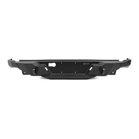
FS-15 SERIES REAR BUMPER
20+ JEEP GLADIATOR JT
RBGL-11
TOOLS
REQUIRED
- T-50 Torque head socket
- #4, #6 Allen head sockets
- 10mm, 15mm, 16mm, 18mm Socket
- 8mm, 10mm, 17mm wrenches
- Snips/Scissors
- File
- Trim Clip Tool
WARNINGS/CAUTIONS BEFORE STARTING INSTALLATION
Before you install this kit —
instructions, warnings, cautions, and notes contained in
this installation instruction guide. Consult your vehicle
owner's manual for proper disconnection of electrical and
lifting of vehicle if required for installation of this product.
This install may require some technical skills and
knowledge of basic mechanical work. If you do not feel that
you are capable of performing this install please take this
product to a trained professional.
After reading this guide please contact us with any
questions or concerns before installing product.
Customer Service: 855-680-9595
DV8 Offroad is not responsible for any bodily injury or harm to you
or your vehicle as a result of an improper install.
6400 SYCAMORE CANYON BLVD.
RIVERSIDE, CALIFORNIA 92507
855-680-9595
WWW.DV8OFFROAD.COM
SKILL
LEVEL
- Novice/Intermediate
- 2 persons
Little skill level required, however,
assistance is required for removal
and installation of bumpers.
Read and understand all
PRODUCT
INSTALLATION
TIME
- 3.5 Hour
Time to install this should only
take about three and a half
hours.
Proper installation of this kit required knowledge of the factory
recommended procedures for removal and installation of original
equipment components. We recommend that the factory shop manual
and any special tools needed to service your vehicle be on hand during
the installation. Installation of this kit without proper knowledge of the
factory recommended procedures may affect the performance of these
components and the safety of the vehicle
• Always wear eye protection when operating power tools
Inspect all contents of this package to make sure product is not damaged
and all installation hardware has been included. If parts are missing from
kit, please be prepared to provide the following information
1. Name of purchase location
2. Bar Code on side of box
3. Date above bar code
4. Date inside box cover
NEED HELP?
MANUAL
REQUIRED
855-680-9595
Advertisement

Related Manuals for DV8 OFFROAD FS-15 Series


Summary of Contents for DV8 OFFROAD FS-15 Series
- Page 1 1. Name of purchase location Customer Service: 855-680-9595 2. Bar Code on side of box DV8 Offroad is not responsible for any bodily injury or harm to you 3. Date above bar code or your vehicle as a result of an improper install.
- Page 2 INSTALLATION MANUAL STEP 1 | If equipped with factory bed sliders, use a 15mm socket to remove the bottom bolts dropping bottom part of slider. If the truck is not equipped with these, skip to step 3. STEP 2 | Repeat on other side.
- Page 3 INSTALLATION MANUAL STEP 3 | Remove trailer plug wiring. Squeeze tab on plug and pull away. They can be difficult, so go slow and ensure no damage to plug. STEP 4 | At the top of the driver side frame rail is the main bumper harness. Remove by pulling the red locking clip back and gently pulling the plug so as not to damage the wiring.
- Page 4 INSTALLATION MANUAL STEP 5 | Unclip the main harness from the frame or any other mounting points that may get caught in the bumper removal process. This will vary depending on the options the truck has (sensors, towing package, etc.). STEP 6 | If the vehicle does not have parking sensors, remove the wiring...
- Page 5 INSTALLATION MANUAL STEP 9 | If equipped with a bumper mounted hitch ball, remove this at this time. If equipped with the factory Class III hitch, you can skip this step. STEP 10 | Using the 16mm socket, remove the four bolts ((2) on each side), holding the bumper to the hitch.
- Page 6 INSTALLATION MANUAL STEP 12 | If equipped with factory bed slider mounts, use a 16mm and 18mm socket the remove the bolts securing the mounting brackets. NEED HELP? 855-680-9595...
- Page 7 INSTALLATION MANUAL STEP 13 | If equipped with factory tow hooks remove both at this time. Use an 18mm socket to remove the bolts securing the factory tow hooks and remove them. If you do not have this option, skip the necessary steps.
- Page 8 INSTALLATION MANUAL Begin by unpacking all items and inspecting for missing pieces or damage. If you have any concerns, please contact the company the product was purchased from. Extra hardware may be included with the product. HARDWARE INCLUDED (2) M10x30 Hex (6) M10 Flat Washers (2) M10x30 Allen (4) M6x20 Allen...
- Page 9 INSTALLATION MANUAL STEP 15 | Disconnect the wiring connector from the license plates on the factory bumper. Press the release tab and pull to remove. Use a trim clip tool if necessary. STEP 16 | There are four tabs on the outside of the license plate light.
- Page 10 INSTALLATION MANUAL STEP 17 | Use snips or a blade to trim down the tab on the top of each light. Then use a file to remove any remaining material. The tab must ground down completely flush with the light assembly. NEED HELP? 855-680-9595...
- Page 11 INSTALLATION MANUAL STEP 18 | Install the factory license plate lights on the DV8 bumper by pressing them into place. STEP 19 | Install the wiring connectors to each license plate light by pressing them into place. NEED HELP? 855-680-9595...
- Page 12 INSTALLATION MANUAL STEP 20 | If equipped with factory sensors, install bezels and sensors in same orientation as OEM. Depending on your specific vehicles sensors, the sensor bezels may clip into place very easily, or it may be necessary to add a small amount of silicone to keep the bezel in place.
- Page 13 INSTALLATION MANUAL STEP 23 | Use the provided M6 hardware to secure the license plate using a #4 allen bit and a 10mm wrench. STEP 24 | With assistance, loosely install the bumper to the vehicle using the provided M10 hardware. Note: Assistance is recommended to prevent injury and damage to the vehicle or product.
- Page 14 INSTALLATION MANUAL STEP 25 | Align the bumper so it is sitting level on the vehicle and secure the hardware. Use a 17mm socket for th upper mounting bolts. Use a #6 allen bit and a 17mm wrench/ socket for the lower mounting bolts. NEED HELP? 855-680-9595...
- Page 15 INSTALLATION MANUAL STEP 26 | Install the trailer wiring harness connector by pressing it firmly into place. STEP 27 | Install the wiring harness connector for the license plate lights/ sensors by pressing them into place. Route the wiring in a secure area over the hitch.
- Page 16 INSTALLATION MANUAL STEP 28 | Secure wiring with zip ties and trim any excess. STEP 29 | Congrats! You are finished with the install of the 20+ Jeep Gladiator JT High Clearance Rear Bumper. NEED HELP? 855-680-9595...
Need help?
Do you have a question about the FS-15 Series and is the answer not in the manual?
Questions and answers