Advertisement
Quick Links
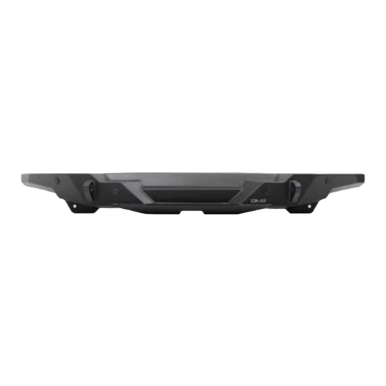
FS-15 REAR BUMPER
18+ JEEP WRANGLER JL
RBJL-11
TOOLS
REQUIRED
- Rubber mallet
- 22g wire (10-14") and connectors
(2-6pcs)
- Zip ties
- Electrical tape/wire loom
- 7, 8, 16, 18, 21mm Sockets
- 10, 17, 18, 21mm Wrench
- #4, #6 Allen Bit
- Wire Cutters/Crimpers
- Blade or Scissors
- Phillips Head Screw Driver
WARNINGS/CAUTIONS BEFORE STARTING INSTALLATION
Before you install this kit —
instructions, warnings, cautions, and notes contained in
this installation instruction guide. Consult your vehicle
owner's manual for proper disconnection of electrical and
lifting of vehicle if required for installation of this product.
This install may require some technical skills and
knowledge of basic mechanical work. If you do not feel that
you are capable of performing this install please take this
product to a trained professional.
After reading this guide please contact us with any
questions or concerns before installing product.
Customer Service: 855-680-9595
DV8 Offroad is not responsible for any bodily injury or harm to you
or your vehicle as a result of an improper install.
6400 SYCAMORE CANYON BLVD.
RIVERSIDE, CALIFORNIA 92507
855-680-9595
WWW.DV8OFFROAD.COM
SKILL
LEVEL
- Novice, Intermediate
- 2 persons
Little skill level required, however,
additional help is required for
removal and installation of
bumpers.
Read and understand all
PRODUCT
INSTALLATION
TIME
- 3 Hours
Time to install this should only
take about three hours
Proper installation of this kit required knowledge of the factory
recommended procedures for removal and installation of original
equipment components. We recommend that the factory shop manual
and any special tools needed to service your vehicle be on hand during
the installation. Installation of this kit without proper knowledge of the
factory recommended procedures may affect the performance of these
components and the safety of the vehicle
• Always wear eye protection when operating power tools
Inspect all contents of this package to make sure product is not damaged
and all installation hardware has been included. If parts are missing from
kit, please be prepared to provide the following information
1. Name of purchase location
2. Bar Code on side of box
3. Date above bar code
4. Date inside box cover
NEED HELP?
MANUAL
REQUIRED
855-680-9595
Advertisement

Related Manuals for DV8 OFFROAD RBJL-11


Summary of Contents for DV8 OFFROAD RBJL-11
- Page 1 1. Name of purchase location Customer Service: 855-680-9595 2. Bar Code on side of box DV8 Offroad is not responsible for any bodily injury or harm to you 3. Date above bar code or your vehicle as a result of an improper install.
- Page 2 INSTALLATION MANUAL STEP 1 | Disconnect the wiring harness for the license plate light. This is located inside the bumper behind the license plate. STEP 2 | Disconnect the bumper wiring harness using a panel clip tool or flat screwdriver to pry open the white locking clip and remove.
- Page 3 INSTALLATION MANUAL STEP 3 | Use a 8mm socket to remove the bolts securing the rear inner fender covers. STEP 4 | Use a 16mm socket to remove the bolts securing the bumper brackets to the bumper. These are located on the edges of the bumper behind the rear tires.
- Page 4 INSTALLATION MANUAL STEP 6 | Remove the remaining brackets from the frame rails using either an 18mm or 21mm socket. Note: The tool required may vary based on model. NEED HELP? 855-680-9595...
- Page 5 INSTALLATION MANUAL Begin by unpacking all items and inspecting for missing pieces or damage. If you have any concerns, please contact the company the product was purchased from. HARDWARE INCLUDED (2) M12x45 Hex (4) M10 Split Washer (2) M12 Flat Washer (4) M10 Nut Clips (2) M12 Split Washer (2) M10 Nylon Lock Nuts...
- Page 6 INSTALLATION MANUAL STEP 8 | Place the provided nut plate into the passenger side of the frame with the nuts facing upwards. STEP 9 | Install the flat nuts into the top two mounting holes on each side of the bumper by pressing them into place.
- Page 7 INSTALLATION MANUAL STEP 11 | Push the sensor bezels into place. The outside bezels should be facing downwards, and the two inside bezels should be facing down and inwards away from the d-ring. A rubber mallet can be used to lightly tap them into place.
- Page 8 INSTALLATION MANUAL STEP 13 | If your bumper was equipped with factory metal bumpers, you will need to pull back the wire cover on the driver-side inside sensor until all wires are exposed. This wire will need to be lengthened 5-10”. STEP 14 | Using wire cutters, cut the wire and prepare ends for wire connectors.
- Page 9 INSTALLATION MANUAL STEP 15 | Insert the extension between the cut wire and secure. Re-wrap harness and continue with the install. If you have any questions, please reach out to our tech team for assistance. STEP 16 | Mount the provided license plate mount to the bumper using the M6 hardware include with the kit.
- Page 10 INSTALLATION MANUAL STEP 17 | Install the provided foam onto the provided license plate light. Then, install the license plate with the provided license plate light on to the license plate mount. Use the provided M4 and M6 hardware with a philips head screwdriver, #4 allen bit, 7mm socket, and a 10mm wrench.
- Page 11 INSTALLATION MANUAL STEP 19 | Loosely secure the bumper to the vehicle using the provided M12 hardware for the nutplate and the factory hardware for all other mounting locations. STEP 20 | Align the bumper left-to- right and up-and-down. Check the wings to ensure neither are touching the body of the vehicle.
- Page 12 INSTALLATION MANUAL STEP 21 | Adjust the in-and-out position of the bumper ensuring there are consistent gaps between the bumper and vehicle, and that the bumper is not touching the vehicle. STEP 22 | Using a 16 mm socket secure the bumper mount bolts. Finish securing all facotry hardware using a 18mm or 21mm socket.
- Page 13 INSTALLATION MANUAL STEP 23 | Double check fitment and function of lights. Double check all hardware is secure. STEP 24 | Congrats! You are finished with the install of the 18+ Jeep Wrangler JL FS-15 Rear Bumper! NEED HELP? 855-680-9595...
Need help?
Do you have a question about the RBJL-11 and is the answer not in the manual?
Questions and answers