Advertisement
Quick Links
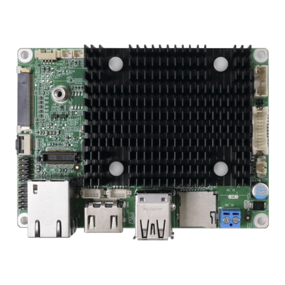
PICO-ITX SBC with Rockchip RK3566 Processor, 2GB/4GB LPDDR4,
16GB/32GB eMMC, HDMI 2.0, MIPI DSI, LVDS, 1GbE RJ45, USB 3.0,
USB 2.0, RS-232/485, 12V DC-IN, Support Android/Linux, RoHS
Quick Installation Guide
Package List
HYPER-RK3566 package includes the following items:
1 x HYPER-RK3566 single board computer
1 x QIG
HYPER-RK3566
Version 1.0
January 4, 2023
©2023 Copyright by IEI Integration Corp.
All rights reserved.
Advertisement

Related Manuals for IEI Technology HYPER-RK3566


Summary of Contents for IEI Technology HYPER-RK3566
- Page 1 USB 2.0, RS-232/485, 12V DC-IN, Support Android/Linux, RoHS HYPER-RK3566 Quick Installation Guide Version 1.0 January 4, 2023 Package List HYPER-RK3566 package includes the following items: 1 x HYPER-RK3566 single board computer 1 x QIG ©2023 Copyright by IEI Integration Corp.
-
Page 2: Specifications
Specifications CPU: Rockchip RK3566 (quad-code Cortex-A55 up to 1.8GHz) Memory: 2GB/4GB LPDDR4/4x, up to 8GB (option: 2GB SKU only supports Linux) SD Card: 1 x microSD slot Flash Memory: 16GB/32GB eMMC NAND flash (option: 16GB SKU only supports Linux) ... - Page 3 All the drivers and utility for the https://download.ieiworld.com HYPER-RK3566 are available on IEI Resource Download Center. Type HYPER-RK3566 and press Enter to find all the relevant software, utilities, and documentation. To install software from the downloaded ISO file, mount the file...
-
Page 4: Jumpers Setting And Connectors
Jumpers Setting and Connectors LABEL FUNCTION RST1 Reset button PWRON1 Power button OTG_ID1 OTG/Host mode setting switch Maskrom recovery connector DEBUG_CN1 Console port connector INV1 Backlight inverter connector BAT1 Battery connector DIO1 GPIO connector LVDS1 LVDS connector MIC1 Microphone connector LCD1 MIPI DSI connector COM1... - Page 5 OTG_ID1: OTG/Host Mode Setting Switch PIN NO. DESCRIPTION Short A - B Host Mode Short B - C OTG Mode (default) J1: Maskrom Recovery Connector PIN NO. DESCRIPTION PIN NO. DESCRIPTION eMMC_D0/FLASH_D0 DEBUG_CN1: Console Port Connector PIN NO. DESCRIPTION PIN NO. DESCRIPTION UART2DBG_TX_C UART2DBG_RX_C...
- Page 6 LVDS1: LVDS Connector PIN NO. DESCRIPTION PIN NO. DESCRIPTION A0P_L A0M_L A1P_L A1M_L A2P_L A2M_L CLK1P_L CLK1M_L A3P_L A3M_L +3V3 +3V3 +3V3 +3V3 LCD1: MIPI DSI Connector PIN NO. DESCRIPTION PIN NO. DESCRIPTION VLED+ TX_D3N VLED+ TX_D2P TX_D2N TX_CLKP TX_CLKN LED- TX_D1P LED-...
- Page 7 COM1: Serial Port Connector PIN NO. DESCRIPTION PIN NO. DESCRIPTION RS232_RXD1 RS485_DATA1- RS232_TXD1 RS485_DATA1+ RS232_RXD2 RS485_DATA2- RS232_TXD2 RS485_DATA2+ MIC1: Microphone Connector DESCRIPTION DESCRIPTION MIC1_INP SPK1: Speaker Connector PIN NO. DESCRIPTION PIN NO. DESCRIPTION SPKP_OUT SPKN_OUT TP1: Touch Connector PIN NO. DESCRIPTION PIN NO.
- Page 8 CN2: Wi-Fi/Bluetooth Connector PIN NO. DESCRIPTION PIN NO. DESCRIPTION UART_RTSn SDMMC_D0 UART_TX SDMMC_D1 UART_RX SDMMC_D2 UART_CTSn SDMMC_D3 SDMMC_CMD I2S_LRCK WIFI2T2R_CLK I2S_SDO I2S_SDI WIFI_REG_ON I2S_SCLK WIFI_WAKE_HOST BT_WAKE_HOST 32KOUT_WIFI HOST_WAKE_BT BT_REG_ON_ WLAN_PEN SDIO_INT SDIO_RESET DC_IN2: Power Input Terminal Block PIN NO. DESCRIPTION PIN NO.
- Page 9 HDMI_CN1: External HDMI Connector PIN NO. DESCRIPTION PIN NO. DESCRIPTION HDMI2_DATA2 HDMI2_DATA2# HDMI2_DATA1 HDMI2_DATA1# HDMI2_DATA0 HDMI2_DATA0# HDMI2_CLK HDMI2_CLK# HDMI2_SCL HDM2I_SDA HDMI2_HPD USB1: External USB 3.0 & USB 2.0 Type-A Connectors PIN NO. DESCRIPTION PIN NO. DESCRIPTION USB3_TX- USB_DATA- USB3_TX+ USB_DATA+ USB_DATA- USB3_RX- USB_ DATA+...
- Page 10 Board Layout: Jumper and Connector Locations (Unit: mm)
Need help?
Do you have a question about the HYPER-RK3566 and is the answer not in the manual?
Questions and answers