Advertisement
Quick Links
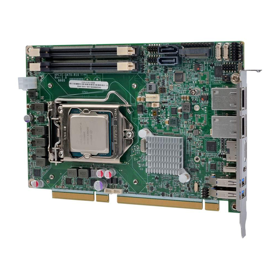
Half-size PICMG 1.3 CPU Card Supports 10
Core™ i9/i7/i5/i3, Pentium® and Celeron® Processors, Intel® Q470,
DDR4 SO-DIMM, HDMI, Dual Intel® 2.5GbE, USB 3.2 Gen 2,
Quick Installation Guide
Package List
HPCIE-Q470 package includes the following items:
1 x HPCIE-Q470 single board computer
1 x SATA cable
1 x QIG
SATA 6Gb/s, M.2, iAudio and RoHS
HPCIE-Q470
Version 1.0
February 24, 2022
© 2022 Copyright by IEI Integration Corp.
All rights reserved.
th
th
/11
Gen. LGA1200 Intel®
Advertisement

Related Manuals for IEI Technology HPCIE-Q470


Summary of Contents for IEI Technology HPCIE-Q470
- Page 1 DDR4 SO-DIMM, HDMI, Dual Intel® 2.5GbE, USB 3.2 Gen 2, SATA 6Gb/s, M.2, iAudio and RoHS HPCIE-Q470 Quick Installation Guide Version 1.0 February 24, 2022 Package List HPCIE-Q470 package includes the following items: 1 x HPCIE-Q470 single board computer 1 x SATA cable 1 x QIG ©...
-
Page 2: Specifications
Specifications CPU: Generation LGA1200 Intel® Core™ i9/i7/i5/i3, Pentium® and Celeron® processors Chipset: Intel® Q470 Memory: Two 260-pin 2933 MHz dual-channel DDR4 SO-DIMM slots supporting up to 64 GB memory BIOS: AMI UEFI BIOS Graphics Engine: 10th Generation CML-S: up to Intel®... - Page 3 (2x5 pin, p=2.0) Front Panel: 1 x Front panel (1x10 pin, p=2.54; power LED, HDD LED, power button, reset button) LAN LED: 2 x LAN LED (1x2 pin, p=2.54) Expansions: 16-lane PCIe signal from CPU via golden finger (supporting x16, or x8 + x8, or x4 + x4 + x8) 4-lane PCIe signal from PCH via golden finger (supporting x4, or x1 + x1 + x1 + x1)
- Page 4 All the drivers and utility for the https://download.ieiworld.com HPCIE-Q470 are available on IEI Resource Download Center. Type HPCIE-Q470 and press Enter to find all the relevant software, utilities, and documentation. To install software from the downloaded ISO file, mount the file as a virtual drive to view its...
-
Page 5: Ordering Information
Ordering Information HPCIE-Q470-R10: Half-size PICMG 1.3 CPU Card supports 10th/11th Gen. LGA1200 Intel® Core™ i9/i7/i5/i3, Pentium® and Celeron® processors, Intel® Q470, DDR4 SO-DIMM, HDMI, dual Intel® 2.5GbE, USB 3.2 Gen 2, SATA 6Gb/s, M.2, iAudio and RoHS CB-USB02A-RS: Dual port USB cable with bracket, 300mm, p=2.0... -
Page 6: Jumpers Setting And Connectors
Jumpers Setting and Connectors LABEL FUNCTION J_ATX_AT1 AT/ATX power mode setting SW_BIOS1_1 BIOS selection switch J_CMOS1 Clear CMOS jumper J_FLASH1 Flash descriptor security override jumper CPU12V1 ATX CPU 12V power connector J_AUDIO1 Audio connector BAT1 RTC battery connector CHASSIS1 Chassis intrusion connector DIMM1, DIMM2 DDR4 SO-DIMM slots DIO1... - Page 7 J_ATX_AT1: AT/ATX Power Mode Setting PIN NO. DESCRIPTION Short 1 - 2 ATX Power Mode (default) Short 2 - 3 AT Power Mode SW_BIOS1_1: BIOS Selection Switch PIN NO. DESCRIPTION Short A - B BIOS1: four PCIe x1 slots (default) Short B - C BIOS2: one PCIe x4 slot J_CMOS1: Clear CMOS Jumper...
- Page 8 CPU12V1: ATX CPU 12V Power Connector PIN NO. DESCRIPTION PIN NO. DESCRIPTION +12V +12V J_AUDIO1 : Internal Audio Connector for IEI Audio Module PIN NO. DESCRIPTION PIN NO. DESCRIPTION HDA_SYNC HDA_BIT_CLK HDA_SDOUT HDA_SPKR HDA_SDIN HDA_RST# HDA_VCC HDA_GND HDA_+12V HDA_GND BAT1: RTC Battery Connector PIN NO.
- Page 9 DBG_SPI1: EC Debug Connector PIN NO. DESCRIPTION PIN NO. DESCRIPTION EDICS EDIDO EDICLK EDIDI CPU_FAN1: CPU Fan Connector PIN NO. DESCRIPTION PIN NO. DESCRIPTION +12V FANIO JSPI1: Flash SPI ROM Connector PIN NO. DESCRIPTION PIN NO. DESCRIPTION +3.3V SPI_CLK SPI_CS# SPI_SI SPI_SO JEC1: Flash EC ROM Connector...
- Page 10 I2C1: I C Connector PIN NO. DESCRIPTION PIN NO. DESCRIPTION I2C_CLK I2C_DATA LED_LAN1: LAN1 Link LED Connector DESCRIPTION DESCRIPTION +3.3V LAN1_LED_LNK#_ACT LED_LAN2: LAN2 Link LED Connector DESCRIPTION DESCRIPTION +3.3V LAN2_LED_LNK#_ACT COM1, COM2: RS-232/422/485 Serial Port Connectors PIN NO. DESCRIPTION PIN NO. DESCRIPTION...
- Page 11 S_ATA1, S_ATA2: SATA 6Gb/s Connectors PIN NO. DESCRIPTION PIN NO. DESCRIPTION SATA_RX‐ SATA_TX+ SATA RX+ SATA_TX‐ SMB1: SMBus Connector PIN NO. DESCRIPTION PIN NO. DESCRIPTION SMB_CLK SMB_DATA SPK1: Speaker Connector PIN NO. DESCRIPTION PIN NO. DESCRIPTION +V5S PC_BEEP USB2: Internal USB 2.0 Connector PIN NO.
- Page 12 PCIE_TX1+ PCIE_TX1- PCIE_RX1+ PCIE_RX1- PCIE_CLK0+ PCIE_CLK0- PLT_RST CLKREQ0# Pull up +3.3V PCIE_WAKE Pull up +3.3V M2_DAT PCIE_TX2+ M2_CLK PCIE_TX2- PCIE_RX2+ M2_RST PCIE_RX2- CLKREQ0# PCIE_WAKE PCIE_CLK1+ +3.3V PCIE_CLK1- +3.3V...
- Page 13 M2_M1: M.2 M-key Slot PIN NO. DESCRIPTION PIN NO. DESCRIPTION +3.3V +3.3V PCIE_RX3+ PCIE_RX3- M2_SSD_PLN +3.3V PCIE_TX3+ +3.3V PCIE_TX3- +3.3V +3.3V PCIE_RX2+ +3.3V PCIE_RX2- PCIE_TX2+ PCIE_TX2- PCIE_RX1+ PCIE_RX1- PCIE_TX1+ PCIE_TX1- SATA_SSD_SLP PCIE_RX0+ PCIE_RX0- PCIE_TX0+ PCIE_TX0- M2_RST CLKREQ0# PCIECLK- PCIE_WAKE PCIECLK+ Module Key Module Key Module Key...
- Page 14 PEDET +3.3V +3.3V +3.3V LAN1, LAN2: External 2.5GbE RJ-45 Connectors PIN NO. DESCRIPTION PIN NO. DESCRIPTION MDIA3- MDIA1+ MDIA3+ MDIA2+ MDIA2- MDIA0- MDIA1- MDIA0+ HDMI1: External HDMI Connector PIN NO. DESCRIPTION PIN NO. DESCRIPTION HDMI_DATA2 HDMI_CLK# HDMI_DATA2# HDMI_DATA1 HDMI_SCL HDMI_DATA1# HDMI_SDA HDMI_DATA0 HDMI_DATA0#...
- Page 15 CN1, CN2: External USB 3.2 Gen 1 Connectors (Type-A) PIN NO. DESCRIPTION PIN NO. DESCRIPTION USB3_RX+ USB_DATA- USB_DATA+ USB3_TX- USB3_TX+ USB3_RX- CON1: External USB 3.2 Gen 2 Connector (Type-C) PIN NO. DESCRIPTION PIN NO. DESCRIPTION TX1+ RX1+ TX1- RX1- VBUS VBUS SBU2 SBU1...
- Page 16 Board Layout: Jumper and Connector Locations (Unit: mm)
Need help?
Do you have a question about the HPCIE-Q470 and is the answer not in the manual?
Questions and answers