Advertisement
Quick Links
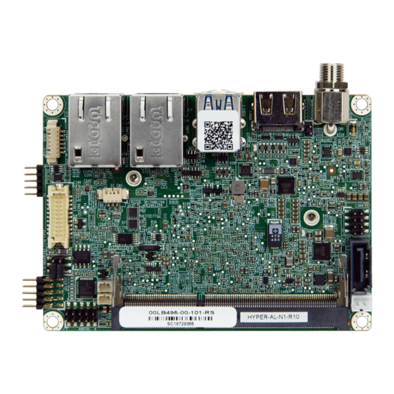
PICO-ITX SBC supports Intel® 14nm Apollo Lake on-board SoC with
DDR3L, HDMI, LVDS, dual GbE, USB 3.0, SATA, M.2 and RoHS
Quick Installation Guide
Package List
HYPER-AL package includes the following items:
1 x HYPER-AL single board computer
1 x SATA cable kit
1 x COM port cable
1 x Heat spreader
4 x Brass male-female spacer (M3*20mm, thread: 6mm)
1 x QIG (Quick Installation Guide)
HYPER-AL
Version 1.0
Sep 12, 2018.
©2018 Copyright by IEI Integration corp.
All rights reserved.
1
Advertisement

Related Manuals for IEI Technology HYPER-AL


Summary of Contents for IEI Technology HYPER-AL
- Page 1 DDR3L, HDMI, LVDS, dual GbE, USB 3.0, SATA, M.2 and RoHS HYPER-AL Quick Installation Guide Version 1.0 Sep 12, 2018. Package List HYPER-AL package includes the following items: 1 x HYPER-AL single board computer 1 x SATA cable kit ...
- Page 2 Specifications SoC: Intel® Celeron® N3350 on-board SoC (up to 2.4GHz, dual-core, 2M Cache, TDP=6W) BIOS: AMI UEFI BIOS Memory: One 204-pin 1866/1600MHz single-channel DDR3L SDRAM unbuffered SO-DIMM slot (system max. 8GB) Graphics Engine: Intel® HD Graphics Gen9 Low Power, 18 Execution Units 4K Codec Decode &...
-
Page 3: Ordering Information
All the drivers and One Key Recovery https://download.ieiworld.com utility for the HYPER-AL are available on IEI Resource Download Center. Type HYPER-AL and press Enter to find all the relevant software, utilities, and documentation. To install software from the downloaded ISO file, mount the file as a virtual drive to view its content. - Page 4 M.2, USB 3.0, SATA 6GB/s, COM and RoHS 32001-008600-200-RS: Dual port USB cable, 210mm, P=2.0 AC-KIT-892HD-R10: Realtek ALC892 7.1 Channel HD Audio peripheral board, RoHS...
-
Page 5: Jumpers Setting And Connectors
Jumpers setting and connectors LABEL FUNCTION J_ATX_AT1 AT/ATX Power Mode Setting J_VLVDS1 LCD Power Select CMOS Battery Connector COM1 Internal RS-232 Serial Port Connector DIO1 Digital Input / Output Connector HDMI1 HDMI Connector LAN1, LAN2 RJ45 LAN Connectors JSPI1 BIOS SPI Connector AUDIO1 Audio Connector USB3-1... - Page 6 BT1: CMOS Battery Connector PIN NO. DESCRIPTION PIN NO. DESCRIPTION COM1: Internal RS-232 Serial Port Connector PIN NO. DESCRIPTION PIN NO. DESCRIPTION NDCD NDSR NSIN NRTS NSOUT NCTS NDTR DIO1: Digital Input / Output Connector PIN NO. DESCRIPTION PIN NO. DESCRIPTION VCC +5V DGPO3...
- Page 7 LAN1, LAN2: RJ45 LAN Connectors PIN NO. DESCRIPTION PIN NO. DESCRIPTION MDI0+ MDI3- MDI0- +3.3Vsus MDI1+ ACT-1 LINK1000 MDI1- +3.3Vsus LINK100 +3.3Vsus MDI2+ MDI2- MDI3+ JSPI1: BIOS SPI Connector PIN NO. DESCRIPTION PIN NO. DESCRIPTION +1.8V SPI_CS SPI_SO SPI_CLK SPI_SI AUDIO1: Audio Connector PIN NO.
- Page 8 USB3-1: External USB 3.0 Connector PIN NO. DESCRIPTION PIN NO. DESCRIPTION 2.0_D0- 2.0_D0+ 3.0_RX1- 3.0_RX1+ 3.0_TX1- 3.0_TX1+ 2.0_D1- 2.0_D1+ 3.0_RX2- 3.0_RX2+ 3.0_TX2- 3.0_TX2+ USB2-1: USB 2.0 Connector PIN NO. DESCRIPTION PIN NO. DESCRIPTION +5Vsus +5Vsus HUB_D1- HUB_D2- HUB_D1+ HUB_D2+ SATA_PWR1: HDD Power Connector PIN NO.
- Page 9 CN5: DC +12V Power Jack Connector PIN NO. DESCRIPTION PIN NO. DESCRIPTION +12V LVDS1: LVDS Connector PIN NO. DESCRIPTION PIN NO. DESCRIPTION A1M_L A0M_L A1P_L A0P_L- CLK1M_L A2M_L CLK1P_L A2P_L A3M_L LVDS Detect (GND)* A3P_L +VCC_LCD +VCC_LCD * LVDS Detect must be connected to GND. INV_CN1: Inverter Connector PIN NO.
- Page 10 M2_CN1: M.2 A Key Card Connector DESCRIPTION DESCRIPTION +V3.3A USB_+DATA7 +V3.3A USB_-DATA7 PCIE_TXP3 PCIE_TXN3 PCIE_RXP3 PCIE_RXN3 CLK_PCIE_M.2_2_P CLK_PCIE_M.2_2_N PCIRST# +V3.3A +V3.3A...
- Page 11 +V3.3A +V3.3A M2_1: M.2 B Key Card Connector DESCRIPTION DESCRIPTION VCC3 VCC3 USB_+DATA6 USB_-DATA6 USB3_RX2_N USB3_RX2_P USB3P0_TXDNM2 USB3P0_TXDPM2 M1_SATA_RX1+_C M1_SATA_RX1-_C M1_SATA_TX1-_C M1_SATA_TX1+_C...
- Page 12 Reset VCC3 VCC3 VCC3...
- Page 13 Board Layout: Jumper and Connector Locations (Unit: mm)
Need help?
Do you have a question about the HYPER-AL and is the answer not in the manual?
Questions and answers