Table of Contents
Advertisement
Quick Links
The Model G0962 is the same machine as the Model G0962A40 except for the 40th Anniversary paint
scheme, inventory, assembly, labeling, and circuit breaker on the motor junction box. Besides the differ-
ences noted in this insert, all other content in the Model G0962A40 series owner's manual applies to this
machine.
: To reduce the risk of serious injury, you MUST read and understand this insert—and
the entire Model G0962A40 manual—BEFORE assembling, installing, or operating this machine!
If you have any further questions about this manual insert or the differences between the Model G0962A40
and the Model G0962, contact our Technical Support at (570) 546-9663 or email techsupport@grizzly.com.
COPYRIGHT © SEPTEMBER, 2023 BY GRIZZLY INDUSTRIAL, INC., REVISED MARCH, 2024 (JA)
WARNING: NO PORTION OF THIS MANUAL MAY BE REPRODUCED IN ANY SHAPE
OR FORM WITHOUT THE WRITTEN APPROVAL OF GRIZZLY INDUSTRIAL, INC.
5012917
#KS22873 PRINTED IN TAIWAN
***Keep for Future Reference***
MODEL G0962
10" 2 HP OPEN-STAND
HYBRID TABLE SAW
MANUAL INSERT
For Machines Mfd. Since 02/24
and Owner's Manual Printed 08/22
V2.03.24
Advertisement
Chapters
Table of Contents

Related Manuals for Grizzly G0962


Summary of Contents for Grizzly G0962
- Page 1 For Machines Mfd. Since 02/24 and Owner's Manual Printed 08/22 The Model G0962 is the same machine as the Model G0962A40 except for the 40th Anniversary paint scheme, inventory, assembly, labeling, and circuit breaker on the motor junction box. Besides the differ- ences noted in this insert, all other content in the Model G0962A40 series owner's manual applies to this machine.
- Page 2 To reset, wait a few minutes for motor to cool, then press reset button. If button does not stay Figure 4. Fence lock handle. depressed, allow motor to cool longer, then try again. Model G0962 (Mfd. Since 02/24)
- Page 3 MACHINE DATA SHEET Customer Service #: (570) 546-9663 · To Order Call: (800) 523-4777 · Fax #: (800) 438-5901 MODEL G0962 10" 2 HP OPEN‐STAND HYBRID TABLE SAW Product Dimensions: Weight................................243 lbs. Width (side-to-side) x Depth (front-to-back) x Height..............64 x 40-1/2 x 36 in.
- Page 4 The information contained herein is deemed accurate as of 3/7/2024 and represents our most recent product specifications. Model G0962 PAGE 2 OF 3 Due to our ongoing improvement efforts, this information may not accurately describe items previously purchased. Model G0962 (Mfd. Since 02/24)
- Page 5 The information contained herein is deemed accurate as of 3/7/2024 and represents our most recent product specifications. Model G0962 PAGE 3 OF 3 Due to our ongoing improvement efforts, this information may not accurately describe items previously purchased. Model G0962 (Mfd. Since 02/24)
-
Page 6: Table Of Contents
Fence Assembly ......... 1 Hardware (Not Shown) Hex Bolts M8-1.25 x 65 (Casters) ..... 3 Figure 5. Model G0962 inventory. Lock Nuts M8-1.25 (Casters) ......3 Cap Screws M10-1.5 x 25 (Ext. Wing/Table) ..6 Flat Washers 10mm (Ext. Wing/Table) ....6 Lock Washers 10mm (Ext. - Page 7 Install caster on each lever and bracket assembly with M8-1.25 x 65 hex bolt and M8-1.25 lock nut (see Figure 7). Figure 9. Caster installed on leg brace. Lever and Bracket Assembly Caster Figure 7. Caster installed on front right leg. Model G0962 (Mfd. Since 02/24)
-
Page 8: Extension Wings
Figure 11). Lock Washer 10mm Blade Tilt Flat Washer Indicator 10mm Extension Wings Blade Tilt Handwheel Blade Elevation Handwheel Figure 11. Example of blade tilt indicator and angle scale. Figure 12. Example of extension wings installed. Model G0962 (Mfd. Since 02/24) - Page 9 Masking Tape Slot Figure 13. Masking tape location for tilting extension wing up. Scale Figure 16. Hex bolt positioned in front fence rail slot. Masking Tape Figure 14. Masking tape location for tilting extension wing down. Model G0962 (Mfd. Since 02/24)
- Page 10 Figure 20. Secure outer four cap screws with Figure 18). Do not fully tighten fasteners at M8-1.25 hex nuts. this time. Rear Fence Rail Figure 18. Example of front fence rail mounted. Figure 20. Example of mounting rear fence rail. -10- Model G0962 (Mfd. Since 02/24)
- Page 11 Fence Figure 23. Example of fence scale calibration. 23. Fully tighten hex nuts from Step 13 to secure front fence rail. Front Fence Rail Figure 22. Example of fence installed on front rail. -11- Model G0962 (Mfd. Since 02/24)
-
Page 12: Spreader/Riving Knife
Front Fence Rail Figure 26. Attaching front end of fence rail brace. 31. Re-install end cap and tap screw on right end of fence rail. -12- Model G0962 (Mfd. Since 02/24) - Page 13 (see Figure 28). 35. Secure motor cover with (6) M5-.8 x 10 but- ton head cap screws (see Figure 28). Figure 28. Example of rear access panel and motor cover installed. -13- Model G0962 (Mfd. Since 02/24)
-
Page 14: Qty
Circuit Breaker 20A (P0962029-11X) ....1 wiring is included in the wiring diagram on NEMA Plug 6-15 ..........1 Page 15 of this insert. To convert machine to 240V: DISCONNECT MACHINE FROM POWER! Cut off existing 5-15 plug. -14- Model G0962 (Mfd. Since 02/24) - Page 15 Technical Support at (570) 546-9663. The photos and diagrams included in this section are best viewed in color. You can view these pages in color at www.grizzly.com. -15- Model G0962 (Mfd. Since 02/24)
- Page 16 30uF 350VAC Start Capacitor CD60 200uF 250VAC Circuit LINE Breaker LOAD Motor (Re-wired for 240V) Ground Run Capacitor CBB60 30uF 350VAC Start Capacitor CD60 200uF 250VAC READ ELECTRICAL SAFETY -16- Model G0962 (Mfd. Since 02/24) ON PAGE 15 OF INSERT!
- Page 17 Electrical Components Figure 32. START/STOP switch wiring. Figure 34. Motor wiring label inside junction box. Figure 35. Motor wiring (120V). Figure 33. Run and start capacitors. READ ELECTRICAL SAFETY -17- Model G0962 (Mfd. Since 02/24) ON PAGE 15 OF INSERT!
- Page 18 PARTS We do our best to stock replacement parts when possible, but we cannot guarantee that all parts shown are available for purchase. Call (800) 523-4777 or visit www.grizzly.com/parts to check for availability. Main 29-6 29-11 29-1 29-2 29-7 29-11X...
- Page 19 DADO TABLE INSERT P0962064 BEARING SEAT P0962125 HEX WRENCH 2.5MM P0962065 HEX NUT M5-.8 P0962127 TRUNNION BRACKET P0962066 CAP SCREW M5-.8 X 10 -19- BUY PARTS ONLINE AT GRIZZLY.COM! Model G0962 (Mfd. Since 02/24) Scan QR code to visit our Parts Store.
- Page 20 P0962214 ARBOR WRENCH 13 X 22MM CLOSED-ENDS 209V2 P0962209V2 BUTTON HD CAP SCR M5-.8 X 16 V2.02.24 P0962215 PUSH STICK P0962210 CAP SCREW M5-.8 X 25 -20- BUY PARTS ONLINE AT GRIZZLY.COM! Model G0962 (Mfd. Since 02/24) Scan QR code to visit our Parts Store.
- Page 21 FLAT WASHER 8.3 X 17.5 X 3MM 316V2 P0962316V2 CAP SCREW M10-1.5 X 30 V2.02.24 P0962332 HEX NUT M10-1.5 P0962317 BUTTON HD CAP SCR M6-1 X 10 -21- BUY PARTS ONLINE AT GRIZZLY.COM! Model G0962 (Mfd. Since 02/24) Scan QR code to visit our Parts Store.
- Page 22 400-32 400-48 400-23 400-39 400-20 400-34 400-33 400-22 400-35 400-21 400-37 400-36 400-27 400-26 400-4 400-25 400-28 400-24 400-29 400-25 407-1 -22- BUY PARTS ONLINE AT GRIZZLY.COM! Model G0962 (Mfd. Since 02/24) Scan QR code to visit our Parts Store.
- Page 23 400-33 P0962400-33 LOCK NUT M10-1.5 P0962461 INT TOOTH WASHER 5MM 400-34 P0962400-34 HEX BOLT M6-1 X 40 P0962464 ADJUSTABLE CABLE CLAMP 400-35 P0962400-35 SPRING PLATE -23- BUY PARTS ONLINE AT GRIZZLY.COM! Model G0962 (Mfd. Since 02/24) Scan QR code to visit our Parts Store.
- Page 24 GUARD RAIL P0962526 BLADE GUARD WINDOW COVER P0962512 PHLP HD SCR M5-.8 X 25 P0962527 FENDER WASHER 5 X 18 X 2 -24- BUY PARTS ONLINE AT GRIZZLY.COM! Model G0962 (Mfd. Since 02/24) Scan QR code to visit our Parts Store.
- Page 25 PHLP HD SCR M4-.7 X 6 P0962608 FENDER WASHER 6MM P0962618 RIVET 2 X 5MM P0962609 MITER GAUGE BODY P0962619 MITER SCALE P0962610 MITER BAR -25- BUY PARTS ONLINE AT GRIZZLY.COM! Model G0962 (Mfd. Since 02/24) Scan QR code to visit our Parts Store.
- Page 26 Safety labels help reduce the risk of serious injury caused by machine hazards. If any label comes off or becomes unreadable, the owner of this machine MUST replace it in the original location before resuming operations. For replacements, contact (800) 523-4777 or www.grizzly.com. -26- BUY PARTS ONLINE AT GRIZZLY.COM!
- Page 27 WARRANTY & RETURNS Grizzly Industrial, Inc. warrants every product it sells for a period of 1 year to the original purchaser from the date of purchase. This warranty does not apply to defects due directly or indirectly to misuse, abuse, negligence, accidents, repairs or alterations or lack of maintenance.
- Page 29 (For models manufactured since 07/22) COPYRIGHT © AUGUST, 2022 BY GRIZZLY INDUSTRIAL, INC. WARNING: NO PORTION OF THIS MANUAL MAY BE REPRODUCED IN ANY SHAPE OR FORM WITHOUT THE WRITTEN APPROVAL OF GRIZZLY INDUSTRIAL, INC. #KS22397 PRINTED IN TAIWAN V1.08.22...
- Page 30 This manual provides critical safety instructions on the proper setup, operation, maintenance, and service of this machine/tool. Save this document, refer to it often, and use it to instruct other operators. Failure to read, understand and follow the instructions in this manual may result in fire or serious personal injury—including amputation, electrocution, or death.
- Page 31 Crosscut Sled..........57 SECTION 1: SAFETY ........9 Safety Instructions for Machinery ....9 SECTION AFTERMARKET ACCESSORIES FROM GRIZZLY ....58 Additional Safety for Table Saws ....11 Preventing Kickback ........12 SECTION 7: MAINTENANCE ......61 Protecting Yourself From Kickback....12 Schedule ............
-
Page 32: Introduction
ID label. This will help us help you faster. tions, specifications, drawings, and photographs in this manual. Sometimes we make mistakes, but Grizzly Technical Support our policy of continuous improvement also means that sometimes the machine you receive is 1815 W. -
Page 33: Front Fence Rail
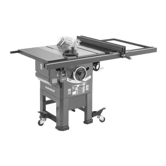
Identification Become familiar with the names and locations of the controls and features shown below to better understand the instructions in this manual. Right Miter Blade Left Fence Extension Rear Gauge Guard Extension Wing Scale Fence Wing Rail Fence Rail Brace START/STOP Fence... -
Page 34: Controls & Components
Controls & B. Handwheel Locks: Lock blade height and angle when tightened (one on each Components handwheel). C. Blade Tilt Handwheel: Adjusts angle of blade tilt from 0°–45°. D. Blade Height Handwheel: Adjusts blade To reduce your risk of height from 0"–3 ⁄... -
Page 35: Glossary Of Terms
The following is a list of common definitions, terms and phrases used throughout this manual as they relate to this table saw and woodworking in general. Become familiar with these terms for assembling, adjusting or operating this machine. Your safety is VERY important to us at Grizzly! Arbor: A metal shaft extending from the drive... -
Page 36: Machine Data Sheet
MACHINE DATA SHEET Customer Service #: (570) 546-9663 · To Order Call: (800) 523-4777 · Fax #: (800) 438-5901 MODEL G0962A40 10" 2 HP OPEN‐STAND HYBRID TABLE SAW ‐ 40TH ANNIVERSARY EDITION Product Dimensions: Weight................................243 lbs. Width (side-to-side) x Depth (front-to-back) x Height..............64 x 40-1/2 x 36 in. Footprint (Length x Width)........................ - Page 37 Main Specifications: Main Information Table Saw Type............................Hybrid Maximum Blade Diameter......................... 10 in. Arbor Size..............................5/8 in. Arbor Speed............................3450 RPM Maximum Width of Dado........................13/16 in. Blade Tilt Direction............................Left Max Blade Tilt............................ 0 - 45 deg. Maximum Depth of Cut At 90 Degrees....................3-1/4 in. Maximum Depth of Cut At 45 Degrees....................
- Page 38 Other Specifications: Country of Origin .............................. Taiwan Warranty ................................1 Year Approximate Assembly & Setup Time ......................1 Hour Serial Number Location ..........................ID Label Sound Rating .............................. 81 - 83 dB ISO 9001 Factory ..............................Yes Features: Precision-Ground Cast-Iron Table Powder Coated Steel Extension Wings Cast Iron Trunnions Easy-Glide Fence System...
-
Page 39: Section 1: Safety
SECTION 1: SAFETY For Your Own Safety, Read Instruction Manual Before Operating This Machine The purpose of safety symbols is to attract your attention to possible hazardous conditions. This manual uses a series of symbols and signal words intended to convey the level of impor- tance of the safety messages. - Page 40 WEARING PROPER APPAREL. Do not wear FORCING MACHINERY. Do not force machine. clothing, apparel or jewelry that can become It will do the job safer and better at the rate for entangled in moving parts. Always tie back or which it was designed. cover long hair.
-
Page 41: Additional Safety For Table Saws
Additional Safety for Table Saws Serious cuts, amputation, or death can occur from contact with rotating saw blade during operation. Workpieces, broken blades, or flying particles thrown by blade can blind or strike operators or bystanders with deadly force. To reduce the risk of these hazards, operator and bystanders MUST completely heed the hazards and warnings below. -
Page 42: Preventing Kickback
Preventing Kickback • Never move the workpiece backwards or try to back it out of a cut while the blade is mov- ing. If you cannot complete a cut for some reason, stop the saw motor and allow the Below are ways to avoid the most common blade to completely stop before backing the causes of kickback: workpiece out. -
Page 43: Section 2: Power Supply
SECTION 2: POWER SUPPLY Availability Circuit Information Before installing the machine, consider the avail- A power supply circuit includes all electrical ability and proximity of the required power supply equipment between the breaker box or fuse panel circuit. If an existing circuit does not meet the in the building and the machine. - Page 44 Grounding Requirements GROUNDED This machine MUST be grounded. In the event 6-15 RECEPTACLE of certain malfunctions or breakdowns, grounding Current Carrying Prongs reduces the risk of electric shock by providing a path of least resistance for electric current. 6-15 PLUG For 120V operation: This machine is equipped with a power cord that has an equipment-ground- ing wire and a grounding plug (see following fig-...
-
Page 45: Converting Voltage To 240V
Converting Voltage Open motor junction box, remove two wire nuts indicated in Figure 6, and then discon- to 240V nect wires. To Switch Electrocution, shock, fire, or damage may occur if machine is ungrounded, incorrectly connected to power, or NOT connected to a proper power supply. -
Page 46: Section 3: Setup
IMPORTANT: Save all packaging materials until you are completely satisfied with the machine and have resolved any issues between Grizzly or the shipping agent. You MUST have the original pack- aging to file a freight claim. It is also extremely helpful if you need to return your machine later. -
Page 47: Hex Bolt M8-1.25 X 16 (Switch/Fence Brace)
Inventory The following is a list of items shipped with your machine. Before beginning setup, lay these items out and inventory them. If any non-proprietary parts are missing (e.g. a nut or a washer), we will gladly replace them; or for the sake of expediency, replacements can be obtained at your local hardware store. -
Page 48: Hardware Recognition Chart
Hardware Recognition Chart USE THIS CHART TO MATCH UP HARDWARE DURING THE INVENTORY AND ASSEMBLY PROCESS. Flat Head Screw -18- Model G0962A40 (Mfd. Since 07/22) -
Page 49: Cleanup
Cleanup Gasoline and petroleum products have low flash The unpainted surfaces of your machine are points and can explode coated with a heavy-duty rust preventative that or cause fire if used to prevents corrosion during shipment and storage. clean machinery. Avoi d This rust preventative works extremely well, but it u sing t h e s e p r o d u c t s will take a little time to clean. -
Page 50: Site Considerations
Site Considerations Weight Load Physical Environment Refer to the Machine Data Sheet for the weight The physical environment where the machine is of your machine. Make sure that the surface upon operated is important for safe operation and lon- which the machine is placed will bear the weight gevity of machine components. -
Page 51: Assembly
Assembly Install leg brace with pre-installed (4) M8-1.25 x 16 button head cap screws and (4) M6-1 x 12 button head cap screws (see Figure 13). The machine must be fully assembled before it can be operated. Before beginning the assembly process, refer to Needed for Setup and gather all listed items. - Page 52 Install handwheels on shafts, making sure Inspect mating surfaces of cast iron table notch in each handwheel fits over pin on for burrs or foreign material that may inhibit each shaft, as shown in Figure 15, and then installation of extension wings. secure with star knobs.
- Page 53 Place straightedge across extension wings 10. Remove (2) M8-1.25 x 16 hex bolts from and main table to ensure combined table switch, then remove tap screw and end cap surface is flat. from left end of front fence rail. Insert hex bolts into bottom slot on left end of fence rail —...
- Page 54 12. Re-install end cap and tap screw on fence rail 14. Install switch on hex bolts from Step 10 using (see Figure 22). (2) M8-1.25 hex nuts and (2) 8mm lock wash- ers (see Figure 24). Figure 22. Left end cap re-installed on front fence rail.
- Page 55 16. Install saw blade as instructed in Blade 19. Using blade height handwheel, raise blade Installation on Page 34. 1–2 inches. 17. Install table insert in table opening (see 20. Turn blade tilt handwheel until blade tilt Figure 26). Check to make sure it is flush indicator on front of machine points to 0°...
- Page 56 24. Check fence scale calibration by moving 27. Install blade guard and spreader/riving knife fence to 1" mark on scale and measuring dis- as instructed on Page 35. tance between blade tooth (see Figure 29) and fence. 28. Using a helper, mount fence rail brace to rear fence rail with M8-1.25 x 16 cap screw and M8-1.25 hex nut (see Figure 30).
-
Page 57: Dust Collection
Dust Collection 32. Measure distance (A) from table edge to rear end of fence rail brace, then adjust front end of fence rail brace so it is the same distance (B) from table edge (see Figure 32). 33. Secure front rail brace hex bolt from Step 30 with M8-1.25 hex nut (see Figure 32). -
Page 58: Test Run
Test Run Once assembly is complete, test run the machine to ensure it is properly connected to power and ON / START safety components are functioning correctly. Button If you find an unusual problem during the test run, OFF / STOP immediately stop the machine, disconnect it from Paddle power, and fix the problem BEFORE operating the... -
Page 59: Section 4: Operations
Read books/magazines or get formal training before beginning any proj- ects. Regardless of the content in this sec- tion, Grizzly Industrial will not be held liable for accidents caused by lack of training. -29- Model G0962A40 (Mfd. Since 07/22) -
Page 60: Disabling & Locking Switch
Disabling & Locking Workpiece Switch Inspection The switch can be disabled and locked by insert- Some workpieces are not safe to cut or may ing a padlock through the ON/START button, as require modification before they are safe to cut. shown. -
Page 61: Non-Through & Through Cuts
Non-Through & Through Cuts A through cut is a sawing operation in which the Through Cuts workpiece is completely sawn through, as shown in the Figure below. Examples of through cuts are rip cuts, cross cuts, miter cuts, and beveled cuts. The blade guard assembly MUST be used when Non-Through Cuts performing through cuts. -
Page 62: Blade Selection
Blade Selection Crosscut Blade Features: • Best for cutting across the grain • 60-80 teeth • Alternate top bevel tooth profile • Small hook angle and a shallow gullet Using a blade that does not meet the speci- fied blade size requirements presents a hazardous condition that could cause kick- back, operator injuries, or property damage. - Page 63 Laminate Blade Features: • Best for cutting plywood or veneer • 40-80 teeth Dado blades have a higher risk of kickback • Triple chip tooth profile than normal blades because their larger size • Very shallow gullet applies stronger forces to the workpiece. This risk increases relative to the depth and width of the cut.
-
Page 64: Blade Installation
Blade Installation Install new blade, flange, and arbor nut on arbor (as shown in Figure 47) with teeth fac- ing front of saw. To reduce risk of shock or accidental startup, always disconnect machine from power before adjustments, maintenance, or service. Properly installing the blade is critical to safe cut- ting operations that produce good results. -
Page 65: Blade Guard Assembly
Blade Guard Spreader/Riving Knife The spreader/riving knife is a metal plate that Assembly prevents the newly cut kerf of the workpiece from pinching the back side of the blade, causing kick- back. The term "blade guard" refers to the assembly The spreader/riving knife also acts as a barrier that consists of the clear polycarbonate shield behind the blade, which can help prevent hands... - Page 66 Insert lower set of holes on spreader/riving Push guard lever toward rear of saw, locking knife into bracket slot, and tighten lock lever blade guard. to secure spreader (see Figure 49). 10. Tug upward on blade guard assembly to Note: DO NOT insert upper set of holes on verify that it is locked into spreader.
- Page 67 Anti-Kickback Pawls Disabling Pawls You might disable the pawls if you are concerned The anti-kickback pawls allow the workpiece about them scratching a delicate workpiece, or to travel in only one direction. If the workpiece if you believe that they will obstruct a narrow moves backwards, such as during a kickback, the workpiece and cause feeding difficulty or loss of pawls will dig into the workpiece to slow or stop it.
-
Page 68: Riving Knife
Riving Knife To ensure riving knife works safely, it MUST be aligned with and correctly adjusted to The spreader also functions as a riving knife, blade. See Page 71 for riving knife alignment. which works in the same manner as the spreader, but is used for non-through cuts. -
Page 69: Ripping
When Not to Use Riving Knife Do not use the riving knife with a dado blade Serious injury can be caused by kickback. that has a diameter smaller than 10" in diameter. Kickback is a high-speed ejection of stock Otherwise, the riving knife height will exceed the from table saw toward an operator. -
Page 70: Crosscutting
Crosscutting Miter Cuts "Crosscutting" means cutting across the grain of A miter is an angled crosscut. Miters are usually a natural wood workpiece, usually with a miter cut in the same manner as crosscuts, using the saw. In other man-made materials, such as MDF miter gauge and a predetermined mark on the or plywood, crosscutting means cutting across the workpiece. -
Page 71: Blade Tilt/Bevel Cuts
Blade Tilt/Bevel Cuts The Model G0962A40 can accommodate dado blades up to 10" in diameter. However, you MUST install the included riving knife while using a 10" diameter dado blade, as it provides a barrier When the blade tilt adjustment bolts are properly behind the blade and reduces the risk of hands adjusted (as described starting on Page 67), the being pulled into the blade if kickback occurs. - Page 72 Cutting Dadoes with a Dado Blade To cut dado with dado blades: Because dado blades are much wider than stan- DISCONNECT MACHINE FROM POWER! dard blades, they place a greater amount of force against the workpiece when cutting. This addition- Adjust dado blade to desired depth of cut.
-
Page 73: Rabbet Cutting
Rabbet Cutting Set saw up for type of cut you need to make, depending on whether it is a rip cut (Page 39) or crosscut (Page 40). Commonly used in furniture joinery, a rabbet is an Align blade to cut one side of dado, as shown L-shaped groove cut in the edge of the workpiece. - Page 74 Cutting Rabbets with a Standard Blade Always use push sticks, featherboards, A ripping blade is typically the best blade to use push paddles and other safety accessories for cutting rabbets when using a standard blade whenever possible to increase safety and because it removes sawdust very efficiently (see Page 32 for blade details.) Also, a sacrificial fence control during operations which require...
-
Page 75: Resawing
Resawing Resawing operations require proper pro- cedures to avoid serious injury. Extra care must be taken to prevent kickback when resawing. Any tilting or movement of the workpiece away from the fence will cause kickback. Be certain that stock is flat and straight. - Page 76 Making Resaw Barrier Making Auxiliary Fence When resawing, the resaw barrier acts in tandem An auxiliary fence is necessary if you are resawing with the rip fence to provide tall support for the a workpiece that is taller than it is wide. The fence workpiece.
- Page 77 Components Needed Place auxiliary fence board against fence Flat Hd Cap Screws M6-1 x (Length Varies) ...3–6 face. Place a thin metal shim (such as a ruler) Hex Nuts M6-1 ..........3–6 between table and bottom of auxiliary fence Wood* ⁄ "...
- Page 78 Resawing Operations Place workpiece against auxiliary fence and slide resaw barrier against workpiece, as The table saw motor is pushed to its limits when shown in Figure 75. Now clamp resaw bar- resawing. If the motor starts to bog down, slow rier to top of table saw at both ends.
- Page 79 Plug in table saw, turn it ON, and use a push 10. Repeat Steps 7–9 until blade is close to half stick or push block to feed workpiece through the height of board to be resawn. The ideal blade, using a slow and steady feed rate. completed resaw cut will leave a ⁄...
-
Page 80: Section 5: Shop Made Safety Accessories
SECTION 5: SHOP MADE SAFETY ACCESSORIES Featherboards We recommend using a bandsaw for mak- ing fingers in the next step because it tends Easily made from scrap stock, featherboards to be safer. A table saw can be used, but it provide an added degree of protection against will over-cut the underside of the ends, pro- kickback, especially when used together with... - Page 81 Rout a ⁄ "– ⁄ " wide slot 4"–5" long in Mark a 4" line through center of countersunk workpiece and 1"–2" from short end of feath- hole in center, then use a jig saw with a nar- erboard (see Figure 78). row blade to cut it out.
- Page 82 Mounting Featherboards w/Clamps Mounting Featherboard in Miter Slot Lower saw blade, then adjust fence to desired Lower saw blade, then adjust fence to desired width and secure it. width and secure it. Place workpiece against fence, making sure Place workpiece evenly against fence, mak- it is 1"...
-
Page 83: Push Sticks
Push Sticks Supporting: A second push stick can be used to keep the workpiece firmly against the fence while cutting. When using a push stick in this manner, only apply pressure before the blade; otherwise, When used correctly, push sticks reduce the risk pushing the workpiece against or behind the of injury by keeping hands away from the blade blade will increase the risk of kickback (see Push... -
Page 84: Push Blocks
Push Blocks The notched end of the push block is then used to push the workpiece the rest of the way through the cut, keeping the operator's hands at a safe distance from the blade. A push stick is often When used correctly, a push block reduces the used at the same time in the other hand to sup- risk of injury by keeping hands away from the... -
Page 85: Narrow-Rip Auxiliary Fence & Push Block
Narrow-Rip Auxiliary Note: We recommend cutting hardwood board oversize, then jointing and planing it Fence & Push Block to correct size to make sure board is square and flat. Only use furniture-grade plywood or kiln-dried hardwood to prevent warping. There are designs for hundreds of specialty jigs Pre-drill and countersink (8) pilot holes ⁄... - Page 86 Using Auxiliary Fence & Push Block Place auxiliary fence on table and clamp Auxilliary Fence it to fence at both ends, then adjust dis- tance between auxiliary fence and blade— Blade this determines how wide workpiece will be Workpiece ripped (see Figure 92). Push Stick for Side Push...
-
Page 87: Outfeed & Support Tables
Outfeed & Support Crosscut Sled Tables A crosscut sled (see Figure 96) is a fantastic way to improve the safety and accuracy of cross- One of the best accessories for improving the cutting on the table saw. Most expert table saw safety and ease of using a table saw is simply plac- operators use a crosscut sled when they have ing a large table (outfeed table) behind the saw to... -
Page 88: Section 6: Aftermarket Accessories From Grizzly
To reduce this risk, only install accessories leave highly polished, finish ready surfaces on recommended for this machine by Grizzly. nearly everything they cut. Made in USA. NOTICE With these all purpose blades for table saws you can rip and crosscut 1"... - Page 89 D4216 Figure 101. Point-of-use dust collectors. T28000—”Bear Crawl” Mobile Base We took years of input and months of testing and design to come out with the Grizzly "Bear Crawl" W1053 Mobile Base. Its 1200 lb. capacity, steel and rub- W1007...
- Page 90 Figure 106. Lined gripping gloves. Figure 104. Heavy-duty roller tables. www.grizzly.com 1-800-523-4777 order online at or call -60- Model G0962A40 (Mfd. Since 07/22)
-
Page 91: Section 7: Maintenance
SECTION 7: MAINTENANCE Cleaning & Protecting To reduce risk of shock or accidental startup, always disconnect machine from power before adjustments, Cleaning the Model G0962A40 is relatively easy. maintenance, or service. Vacuum excess wood chips and sawdust, and wipe off the remaining dust with a dry cloth. If any resin has built up, use a resin-dissolving cleaner Schedule to remove it. -
Page 92: Lubrication
Lubrication Worm Gear, Bull Gear & Leadscrew Lubrication Type ... T26419 or NLGI#2 Equivalent Amount ............Dab Lubrication Frequency .....6–12 Months It is essential to clean components before lubri- cating them because dust and chips build up on Clean away any built up grime and debris lubricated components and make them hard to from worm gear, bull gear, and leadscrew (see move. -
Page 93: Section 8: Service
SECTION 8: SERVICE Review the troubleshooting procedures in this section if a problem develops with your machine. If you need replacement parts or additional help with a procedure, call our Technical Support. Note: Please gather the serial number and manufacture date of your machine before calling. Troubleshooting Motor &... - Page 94 Motor & Electrical (Cont.) Symptom Possible Cause Possible Solution Machine has 1. Motor or component loose. 1. Replace damaged or missing bolts/nuts or tighten if vibration or noisy loose. operation. 2. Mobile base lock knobs loose or stand feet not 2.
- Page 95 Machine Operation (Cont.) Symptom Possible Cause Possible Solution Handwheel binds 1. Lock knob is engaged. 1. Loosen lock knob. or blade will not 2. Sawdust/debris stuck in trunnion slides. 2. Clean sawdust/debris out of trunnion slides. move up/down or 3. Handwheel shaft pins are wedged. 3.
- Page 96 Machine Operation (Cont.) Symptom Possible Cause Possible Solution Will not make 1. 90° stop out of adjustment. 1. Adjust 90° stop (Page 67). accurate square cuts. Blade tilt does 1. 45°/90° stop out of adjustment. Sawdust built 1. Adjust 45°/90° stop (Page 67). Remove sawdust not stop at up in/on trunnions.
-
Page 97: Blade Tilt Calibration
Blade Tilt Calibration — If blade is 90° to table, then no adjust- ments are necessary. Make sure tilt indi- cator arrow shown in Figure 112 points to 0° mark on scale. Adjust position by The blade tilt settings for this saw have been set at loosening Phillips head screws, moving the factory and should not require adjustment dur- indicator with your fingers, then tightening... - Page 98 Tilt blade to about 5° so there is room for stop — If blade is 45° to table, then no adjust- nuts to move. ments need to be made. Proceed to Step 8. Loosen stop nuts and adjust according to how far off blade was from 90°.
-
Page 99: Miter Slot To Blade Parallelism
Miter Slot to Blade With end of adjustable square just touching tip, lock square in place. Now, mark car- Parallelism bide tip with a marker where you made this measurement. Your table saw will give the best results if the miter slot and the rip fence are adjusted paral- The saw blade is sharp. - Page 100 Loosen (4) table mounting bolts securing 10. Refer to Figures 119–120 for shim place- table top to base (see Figure 118), and lightly ment. If distance A is shorter than B, shim(s) tap table in direction needed to square table will need to be placed under corners #1 and to blade.
-
Page 101: Spreader Or Riving Knife Alignment
Spreader or Riving 11. Tighten one table mounting bolt a small amount and then repeat with the others, Knife Alignment tightening each down the same amount. Continue this process with all the bolts, tight- ening them a little each time until they are all secure. - Page 102 Loosen (2) cap screws on "L" bracket (see Figure 123), then slide spreader/riving knife Alignment as needed to align with blade. Zone Spreader or Riving Knife Blade Figure 122. Spreader/riving knife alignment zone. — If spreader/riving knife is parallel with blade and inside alignment zone, no adjustment "L"...
-
Page 103: Adjusting Fence
Adjusting Fence To check/adjust fence squareness and height to table: DISCONNECT MACHINE FROM POWER! There are three main adjustments for the fence: (1) square, (2) height, and (3) clamping pressure. Place square on table against face of fence Keep in mind that these adjustments are intercon- (see Figure 126) to check if fence is square nected and some trial-and-error may be needed to table. - Page 104 Measure gap between fence and table top at Re-install fence assembly. front and rear of fence. Reach inside fence and adjust height of bear- — If gap is approximately ⁄ " and even from ing shaft. Turn shaft clockwise to decrease front of table to back (see Figure 127), shaft height;...
-
Page 105: Calibrating Fence To Blade
Calibrating Fence to — If fence is parallel with blade, no further adjustments need to be made. Blade — If fence is not parallel with blade, proceed to Step 3. Two set screws at the front of the fence position Remove fence assembly from front rail. -
Page 106: Fence Scale Calibration
Fence Scale Measure width of freshly cut workpiece at both ends with a tape measure. Workpiece Calibration width should be exactly 12" at front and back. If it is not, then adjust indicator window to match width of workpiece. The fence scale windows, shown in Figure 133, can be calibrated with the fence scale by loosen- Table/Dado Insert ing the mounting screws and sliding them in the... -
Page 107: Calibrating Miter Gauge
Calibrating Miter Place square evenly against miter body and blade, as shown in Figure 136. Gauge — If angle indicator does point to 90° when miter body is square to blade, no adjust- ment is necessary. The miter gauge adjusts between 60° left and 60°... -
Page 108: Belt Tension & Replacement
Belt Tension & Use blade height handwheel to lower motor. When motor starts to pull blade down with it, Replacement belt is tensioned. Retighten blade tension hex bolt, then re-install motor cover. The drive belt stretches slightly as the saw is used. Most stretching will happen during the first 16 Replacing Belt hours of use, but it may slightly continue with fur-... -
Page 109: Section 9: Wiring
Technical Support at (570) 546-9663. The photos and diagrams included in this section are best viewed in color. You can view these pages in color at www.grizzly.com. -79- Model G0962A40 (Mfd. Since 07/22) -
Page 110: Wiring Diagram
Wiring Diagram START/STOP Switch 120 VAC 240 VAC Neutral KEDU HY56 LOAD LINE Ground Ground Ground 5-15 Plug 6-15 Plug (Pre-wired) (As Recommended) Re-wired for 240V Re-wired for 240V Motor (Pre-wired for 120V) Ground Run Capacitor CBB60 30µF 350VAC Start Capacitor CD60 200µF 250VAC Motor... -
Page 111: Electrical Components
Electrical Components Figure 139. START/STOP switch wiring. Figure 141. Junction box motor wiring at 120V. Figure 140. Run and start capacitors. Figure 142. Motor wiring label inside junction box. READ ELECTRICAL SAFETY -81- Model G0962A40 (Mfd. Since 07/22) ON PAGE 79! -
Page 112: Section 10: Parts
SECTION 10: PARTS We do our best to stock replacement parts when possible, but we cannot guarantee that all parts shown are available for purchase. Call (800) 523-4777 or visit www.grizzly.com/parts to check for availability. Main 29-4 29-1 29-7 29-8... - Page 113 123 P0962A40123 CAP SCREW M5-.8 X 10 P0962A40065 HEX NUT M5-.8 124 P0962A40124 DADO TABLE INSERT P0962A40066 CAP SCREW M5-.8 X 10 125 P0962A40125 HEX WRENCH 2.5MM BUY PARTS ONLINE AT GRIZZLY.COM! -83- Model G0962A40 (Mfd. Since 07/22) Scan QR code to visit our Parts Store.
-
Page 114: Cabinet & Stand
HEX BOLT M8-1.25 X 65 P0962A40241 HEX NUT M5-.8 P0962A40221 LOCK NUT M8-1.25 P0962A40242 STAND, 1-PIECE WELDED P0962A40222 FLAT WASHER 8MM P0962A40244 HEX NUT M3-.5 BUY PARTS ONLINE AT GRIZZLY.COM! -84- Model G0962A40 (Mfd. Since 07/22) Scan QR code to visit our Parts Store. -
Page 115: Fence & Rails
300-33 P0962A40300-33 LOCK NUT M10-1.5 P0962A40361 INT TOOTH WASHER 5MM 300-34 P0962A40300-34 HEX BOLT M6-1 X 40 P0962A40364 ADJUSTABLE CABLE CLAMP 300-35 P0962A40300-35 SPRING PLATE BUY PARTS ONLINE AT GRIZZLY.COM! -85- Model G0962A40 (Mfd. Since 07/22) Scan QR code to visit our Parts Store. -
Page 116: Blade Guard
CAP SCREW M5-.8 X 30 P0962A40411 GUARD RAIL FRONT WINDOW P0962A40426 BLADE GUARD WINDOW COVER P0962A40412 PHLP HD SCR M5-.8 X 25 BUY PARTS ONLINE AT GRIZZLY.COM! -86- Model G0962A40 (Mfd. Since 07/22) Scan QR code to visit our Parts Store. -
Page 117: Miter Gauge
PHLP HD SCR M4-.7 X 10 P0962A40512 MITER HANDLE P0962A40529 PHLP HD SCR M4-.7 X 6 P0962A40513 RIVET 2 X 5MM BUY PARTS ONLINE AT GRIZZLY.COM! -87- Model G0962A40 (Mfd. Since 07/22) Scan QR code to visit our Parts Store. -
Page 118: Labels & Cosmetics
Safety labels help reduce the risk of serious injury caused by machine hazards. If any label comes off or becomes unreadable, the owner of this machine MUST replace it in the original location before resuming operations. For replacements, contact (800) 523-4777 or www.grizzly.com. BUY PARTS ONLINE AT GRIZZLY.COM! -88- Model G0962A40 (Mfd. -
Page 119: Warranty & Returns
WARRANTY & RETURNS Grizzly Industrial, Inc. warrants every product it sells for a period of 1 year to the original purchaser from the date of purchase. This warranty does not apply to defects due directly or indirectly to misuse, abuse, negligence, accidents, repairs or alterations or lack of maintenance.
Need help?
Do you have a question about the G0962 and is the answer not in the manual?
Questions and answers