Table of Contents
Advertisement
Quick Links
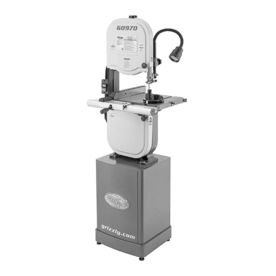
MODEL G0970
14" VERTICAL
METAL-CUTTING BANDSAW
OWNER'S MANUAL
(For models manufactured since 07/23)
COPYRIGHT © AUGUST, 2023 BY GRIZZLY INDUSTRIAL, INC.
WARNING: NO PORTION OF THIS MANUAL MAY BE REPRODUCED IN ANY SHAPE
OR FORM WITHOUT THE WRITTEN APPROVAL OF GRIZZLY INDUSTRIAL, INC.
#JP22777 PRINTED IN TAIWAN
V1.08.23
***Keep for Future Reference***
Advertisement
Table of Contents

Related Manuals for Grizzly G0970


Summary of Contents for Grizzly G0970
- Page 1 (For models manufactured since 07/23) COPYRIGHT © AUGUST, 2023 BY GRIZZLY INDUSTRIAL, INC. WARNING: NO PORTION OF THIS MANUAL MAY BE REPRODUCED IN ANY SHAPE OR FORM WITHOUT THE WRITTEN APPROVAL OF GRIZZLY INDUSTRIAL, INC. #JP22777 PRINTED IN TAIWAN V1.08.23...
- Page 2 This manual provides critical safety instructions on the proper setup, operation, maintenance, and service of this machine/tool. Save this document, refer to it often, and use it to instruct other operators. Failure to read, understand and follow the instructions in this manual may result in fire or serious personal injury—including amputation, electrocution, or death.
-
Page 3: Table Of Contents
Table of Contents INTRODUCTION ..........2 SECTION 5: ACCESSORIES ......41 Contact Info ........... 2 SECTION 6: MAINTENANCE......42 Manual Accuracy ........... 2 Schedule ............42 Identification........... 3 Cleaning & Protecting ........42 Controls & Components......... 4 Lubrication ........... 42 Machine Data Sheet ........ -
Page 4: Introduction
Always consider safety first, as it applies to your individual working conditions. Use this and other machinery with caution and respect. Failure to do so could result in serious personal injury, damage to equip- ment, or poor work results. Model G0970 (Mfd. Since 07/23) -
Page 5: Identification
Do not remove jammed cutoff pieces until blade has stopped. c) Maintain proper adjustment of blade tension, blade guides, and support bearings. d) Adjust upper guide to just clear workpiece. e) Hold workpiece firmly against table. Model G0970 (Mfd. Since 07/23) -
Page 6: Controls & Components
H. Table Tilt Scale: Indicates current angle of table in relation to blade. Table Tilt Lock Knob (1 of 2): Rotate coun- terclockwise to allow table tilt adjustment; rotate clockwise to lock table in position. Model G0970 (Mfd. Since 07/23) - Page 7 O. Blade Tracking Knob: Rotate clockwise to track blade toward back of wheels and counterclockwise to track blade forward on wheels. Model G0970 (Mfd. Since 07/23)
-
Page 8: Machine Data Sheet
MACHINE DATA SHEET Customer Service #: (570) 546-9663 · To Order Call: (800) 523-4777 · Fax #: (800) 438-5901 MODEL G0970 14" VERTICAL METAL‐CUTTING BANDSAW Product Dimensions: Weight................................238 lbs. Width (side-to-side) x Depth (front-to-back) x Height................28 x 25 x 68 in. - Page 9 The information contained herein is deemed accurate as of 8/24/2023 and represents our most recent product specifications. Model G0970 PAGE 2 OF 2 Due to our ongoing improvement efforts, this information may not accurately describe items previously purchased. Model G0970 (Mfd. Since 07/23)
-
Page 10: Section 1: Safety
Never operate under the influence of drugs or injury or blindness from flying particles. Everyday alcohol, when tired, or when distracted. eyeglasses are NOT approved safety glasses. Model G0970 (Mfd. Since 07/23) - Page 11 EXPERIENCING DIFFICULTIES. If at any time debris. Make sure they are properly installed, you experience difficulties performing the intend- undamaged, and working correctly BEFORE ed operation, stop using the machine! Contact our operating machine. Technical Support at (570) 546-9663. Model G0970 (Mfd. Since 07/23)
-
Page 12: Additional Safety For Vertical Metal Bandsaws
HOT SURFACES. Contact with hot surfaces from machine to tip and fall, which could cause serious machine components, ejections of hot chips, injury. swarf, and the workpiece itself can cause burns. -10- Model G0970 (Mfd. Since 07/23) -
Page 13: Section 2: Power Supply
Nominal Voltage ..208V, 220V, 230V, 240V meets the specified circuit requirements. Cycle ............60 Hz Phase ........... Single-Phase Power Supply Circuit ......15 Amps Plug/Receptacle ......NEMA 6-15 -11- Model G0970 (Mfd. Since 07/23) - Page 14 The plug must only be inserted into a matching receptacle (see following figure) that is properly installed and grounded in accordance with all local codes and ordinances. -12- Model G0970 (Mfd. Since 07/23)
-
Page 15: Converting Voltage To 220V
Cut 5-15 plug off end of power cord. Open rear maintenance door, then open motor junction box. Remove wire nuts shown in Figure 8. Remove Wire Nuts To Switch Ground Figure 8. Inside motor junction box. -13- Model G0970 (Mfd. Since 07/23) Run Capacitor 12uF 250VAC... -
Page 16: Section 3: Setup
IMPORTANT: Save all packaging materials until you are completely satisfied with the machine and have resolved any issues between Grizzly or the shipping agent. You MUST have the original pack- aging to file a freight claim. It is also extremely helpful if you need to return your machine later. -
Page 17: Inventory
If you cannot find an item on this list, care- fully check around/inside the machine and packaging materials. Often, these items get lost in packaging materials while unpack- ing or they are pre-installed at the factory. -15- Model G0970 (Mfd. Since 07/23) -
Page 18: Cleanup
Figure 13. T23692 Orange Power Degreaser. Repeat Steps 2–3 as necessary until clean, then coat all unpainted surfaces with a quality metal protectant to prevent rust. -16- Model G0970 (Mfd. Since 07/23) -
Page 19: Site Considerations
Only install in an or remove doors/covers as required by the main- access restricted location. tenance and service described in this manual. See below for required space allocation. " 28" = Electrical Connection Figure 14. Working clearances. -17- Model G0970 (Mfd. Since 07/23) -
Page 20: Assembly
(see Figure 16). Motor Pulley Tilt Handle Adjustable Foot (1 of 4) Figure 18. Motor tilted and locked in place. Figure 16. Foot installed. -18- Model G0970 (Mfd. Since 07/23) - Page 21 12. Line up belt guard slots with knob bolts and slide belt guard against machine, then tighten knob bolts (see Figure 20). 2" Belt Guard Figure 22. Positive stop installed. Figure 20. Belt guard installed. -19- Model G0970 (Mfd. Since 07/23)
- Page 22 19. Thread (1) knob bolt into lower blade guard bottom of trunnion (see Figure 25). bracket (see Figure 26), then line up lower blade guard and secure with knob bolt. Blade Guard Figure 24. Installing table. Figure 26. Installing lower blade guard. -20- Model G0970 (Mfd. Since 07/23)
- Page 23 Tighten hex nut against fence to secure. Fence Figure 28. Example of attaching rear fence rail. Stand-Off Figure 30. Fence stand-off installed. 25. Connect motor power cord to motor cord. -21- Model G0970 (Mfd. Since 07/23)
-
Page 24: Adjustment Overview
Note: The Model G0970 is equipped with a gear ly. Improper tracking reduces cutting accuracy, reducer, which makes turning the wheels by hand causes excess vibrations, and places stress on very difficult. -
Page 25: Test Run
BEFORE operating the machine again. The Troubleshooting table in the SERVICE section of this manual can help. The Test Run consists of verifying the following: 1) The motor powers up and runs correctly. -23- Model G0970 (Mfd. Since 07/23) -
Page 26: Tensioning Blade
The motor should run smoothly and without unusual problems or noises. NOTICE After the first 16 hours of operation, new V-belts will stretch and seat farther into the pulleys. To avoid slippage, re-tension new V-belts after this period. -24- Model G0970 (Mfd. Since 07/23) -
Page 27: Adjusting Blade Guides & Support Bearings
Items Needed Feeler Gauge 0.016".......... 1 Whenever changing a blade or adjusting tension and tracking, upper and lower blade guides and support bearings must be re- adjusted before operation. -25- Model G0970 (Mfd. Since 07/23) - Page 28 Figure 38. G. Blade Guide Block Thumbscrew (1 of 2): Locks blade guide blocks in place. Approximately 0.016" Blade Gullets Figure 38. Blade guide (1 of 2) positioned 0.016" behind blade gullets. -26- Model G0970 (Mfd. Since 07/23)
-
Page 29: Aligning Table
Straightedge 24" ..........1 Square 6"............1 Fine Ruler 12"............ 1 Masking Tape ........As Needed Wrench Open-End 10mm........1 To align table: DISCONNECT MACHINE FROM POWER! Figure 41. Location of trunnion bracket flange bolts. -27- Model G0970 (Mfd. Since 07/23) -
Page 30: Aligning Fence
— If fence is not parallel with miter slot, pro- ceed to Step 3. — If fence scale is aligned with "0", no adjust- ment is necessary. — If fence scale is not aligned with "0", pro- ceed to Step 3. -28- Model G0970 (Mfd. Since 07/23) -
Page 31: Calibrating Miter Gauge
Note: Ensure miter gauge does not move while tightening lock knob. To calibrate miter gauge: Loosen Phillips head screw that secures DISCONNECT MACHINE FROM POWER! pointer, adjust pointer to 0° mark on scale, then tighten screw to secure setting. -29- Model G0970 (Mfd. Since 07/23) -
Page 32: Section 4: Operations
Regardless of the content in this sec- ry. Examples are chains, cables, round or tion, Grizzly Industrial will not be held liable oblong-shaped workpieces, workpieces for accidents caused by lack of training. with internal or built-in moving or rotations parts, etc. -
Page 33: Operation Tips
If needed, use a small amount of oil-based • Magnesium: Pure magnesium burns eas- lubricant. ily. Cutting magnesium with a dull blade can create enough friction to ignite the small magnesium chips. Avoid cutting magnesium, if possible. -31- Model G0970 (Mfd. Since 07/23) -
Page 34: Blade Selection
Measured by the blade circumference, blade lengths are usually unique to the brand of your bandsaw and the distance between the wheels. Selecting the right blade for the cut requires a knowledge of various blade characteristics. G0970 Blade Length Range..... 92 ⁄ "–93 ⁄ "... - Page 35 Hook or Claw: Wide gullets (round or flat), equal- ly spaced teeth, positive rake angle, and fast cut with good surface finish. Skip or Skip Tooth: Wide, flat gullets, a "0" rake angle, equally spaced teeth, and recommended for non-ferrous materials. -33- Model G0970 (Mfd. Since 07/23)
- Page 36 Alloy Tool Steel Cast Iron 203~213 Copper 229~482 85-203 Oil-Hardened CR Stainless Plastics (62) (65) Alloy (70) (147) (26) (62) Tool Steel Steel (67) Figure 51. General guidelines for blade selection and speed chart. -34- Model G0970 (Mfd. Since 07/23)
-
Page 37: Chip Inspection Chart
& curled tightly powdery Figure 52. Chip inspection chart. thin & curled tightly powdery thin & curled tightly powdery thin & curled tightly thin & curled tightly thin & curled tightly thin & curled tightly -35- Model G0970 (Mfd. Since 07/23) -
Page 38: Blade Care & Break-In
NOTICE To prolong blade life, release tension on the blade if the machine will be idle for an extended period of time. -36- Model G0970 (Mfd. Since 07/23) -
Page 39: Changing Blade Speed
(see Figure 55). The Model G0970 has three blade speeds to accommodate the blade type, material being used, and cut being performed. Simply move the Tilt Lock V-belt according to the illustration in Figure 53. -
Page 40: Removing/Installing Blade
Blade Tracking on Page 22). Adjust upper/lower blade guides and support bearings (see Adjusting Blade Guides & Support Bearings on Page 25). Lower Table Pin Blade Guard Figure 57. Location of table insert and pin. -38- Model G0970 (Mfd. Since 07/23) -
Page 41: Calibrating Table Tilt
Figure 59. Table tilt controls. Square Table Figure 61. Checking table tilt accuracy. Positive Stop Bolt Loosen table tilt lock knobs and adjust table Jam Nut so it is 90° to blade. Figure 60. Table tilted. -39- Model G0970 (Mfd. Since 07/23) -
Page 42: Guide Post
Figure 64. Guide post assembly. If necessary, loosen Phillips head screw securing pointer, adjust pointer to 0°, then Position bottom of upper blade guides tighten screw. approximately ⁄ " above workpiece, then tighten lock knob. -40- Model G0970 (Mfd. Since 07/23) -
Page 43: Section 5: Accessories
This To reduce this risk, only install accessories is a high-quality mobile base that will make your recommended for this machine by Grizzly. shop more convenient and efficient and will keep your equipment stable and rolling for years to NOTICE come. -
Page 44: Section 6: Maintenance
Guide Post Cleaning & Protecting Cleaning the Model G0970 is relatively easy. Vacuum excess metal chips and flakes, and wipe off the remaining dust with a dry cloth. Figure 68. Location of guidepost lubrication Protect the unpainted cast iron table by wiping point. -
Page 45: Section 7: Service
13. Centrifugal switch/contact points at fault. 13. Adjust centrifugal switch/clean contact points. Replace either if at fault. 14. Gear reducer at fault. 14. Replace gear reducer. 15. Motor or motor bearings at fault. 15. Replace motor. -43- Model G0970 (Mfd. Since 07/23) - Page 46 Table is hard 1. Table tilt lock knobs are engaged. 1. Disengage table tilt lock knobs (Page 39). to tilt. 2. Metal chips trapped between trunnion and 2. Remove table and clean trunnion sliding surfaces. base. -44- Model G0970 (Mfd. Since 07/23)
- Page 47 1. Excessive feed rate/pressure. 1. Reduce feed rate/pressure. of blade 2. Blade tension too high. 2. Adjust blade tension (Page 24). deformation/ 3. Blade support bearings improperly adjusted. 3. Adjust blade support bearings (Page 25). cracking. -45- Model G0970 (Mfd. Since 07/23)
-
Page 48: Tensioning V-Belt
NOTICE After the first 16 hours of operation, new V-belts will stretch and seat farther into the pulleys. To avoid slippage, re-tension new V-belts after this period. Figure 71. Belt guard installed. -46- Model G0970 (Mfd. Since 07/23) -
Page 49: Adjusting Wheel Brush
Adjust wheel brush so it makes firm contact with wheel but bristles are not overly bent. Tighten screw to secure wheel brush in place, Figure 73. Belt installed on bandsaw pulley. then close lower wheel cover. -47- Model G0970 (Mfd. Since 07/23) -
Page 50: Wheel Alignment
Use upper wheel: Adjust blade tracking knob rear adjustment set to tilt upper wheel. bolts to tilt lower wheel left/right. Figure 76. Wheel alignment illustration. Figure 75. Example of checking if wheels are coplanar. -48- Model G0970 (Mfd. Since 07/23) -
Page 51: Blade Tension Gauge
Gauge With straightedge touching both rims of wheel that does not need to be adjusted, measure The Model G0970 uses a tension gauge system distance away from other wheel with a fine that helps users ensure they are applying consis- ruler, as shown in Figure 77. - Page 52 13. Raise tension lever to release blade tension. — If all tension is released from blade, blade tensioner is properly adjusted. — If all tension is not released, lower spacer needs to be threaded farther down shaft toward sliding bracket. -50- Model G0970 (Mfd. Since 07/23)
-
Page 53: Section 8: Wiring
Technical Support at (570) 546-9663. The photos and diagrams included in this section are best viewed in color. You can view these pages in color at www.grizzly.com. -51- Model G0970 (Mfd. Since 07/23) -
Page 54: Wiring Diagram
200MFD 250VAC Ground Rewired for 220V Neutral 110 VAC 5-15 Plug Ground Ground Run Capacitor 220 VAC 12uF 250VAC 6-15 Plug (As Recommended) Start Capacitor 200MFD 250VAC Ground READ ELECTRICAL SAFETY -52- Model G0970 (Mfd. Since 07/23) ON PAGE 51! -
Page 55: Electrical Components
Electrical Components Figure 81. Junction box wiring. Figure 80. ON/OFF switch wiring. Figure 82. Junction box cover. READ ELECTRICAL SAFETY -53- Model G0970 (Mfd. Since 07/23) ON PAGE 51! -
Page 56: Section 9: Parts
SECTION 9: PARTS We do our best to stock replacement parts when possible, but we cannot guarantee that all parts shown are available for purchase. Call (800) 523-4777 or visit www.grizzly.com/parts to check for availability. Main 22-16 22-19 22-9 22-18... - Page 57 22-12 P0970022-12 SET SCREW M5-.8 X 10 P0970057 DUST PORT CAP 22-13 P0970022-13 LOWER LOCK COLLAR P0970058 FLANGE NUT M8-1.25 22-14 P0970022-14 SET SCREW M5-.8 X 5 -55- BUY PARTS ONLINE AT GRIZZLY.COM! Model G0970 (Mfd. Since 07/23) Scan QR code to visit our Parts Store.
-
Page 58: Wheels & Table
Wheels & Table 116-4 116-3 116-2 116-1 119-6 119-4 119-7 119-3 119-5 119-2 119-1 -56- BUY PARTS ONLINE AT GRIZZLY.COM! Model G0970 (Mfd. Since 07/23) Scan QR code to visit our Parts Store. - Page 59 TABLE TILT SCALE 119-2 P0970119-2 LOWER WHEEL P0970140 HEX BOLT M10-1.5 X 50 119-3 P0970119-3 BUTTON HD CAP SCR 5/16-18 X 3/4 -57- BUY PARTS ONLINE AT GRIZZLY.COM! Model G0970 (Mfd. Since 07/23) Scan QR code to visit our Parts Store.
-
Page 60: Stand & Motor
224-4 P0970224-4 R CAPACITOR 12M 250V 1-1/2 X 1-1/4 X 3/4 207-16 P0970207-16 FIXED HANDLE 20 X 99, M8-1.25 X 22 224-5 P0970224-5 MOTOR JUNCTION BOX P0970208 FLAT WASHER 8MM -58- BUY PARTS ONLINE AT GRIZZLY.COM! Model G0970 (Mfd. Since 07/23) Scan QR code to visit our Parts Store. -
Page 61: Fence & Rails
HEX NUT M8-1.25 P0970311 REAR FENCE RAIL P0970324 HEX BOLT M6-1 X 20 P0970312 HEX NUT M8-1.25 P0970325 FLAT WASHER 6MM -59- BUY PARTS ONLINE AT GRIZZLY.COM! Model G0970 (Mfd. Since 07/23) Scan QR code to visit our Parts Store. -
Page 62: Labels & Cosmetics
Examples are chains, cables, WITHOUT WRITTEN APPROVAL! Grizzly will not accept labels changed without approval. COPYRIGHT © GRIZZLY INDUSTRIAL, INC. round or oblong-shaped work- pieces, workpieces with internal FOR GRIZZLY MACHINES ONLY! DO NOT REPRODUCE OR CHANGE THIS ARTWORK artwork changes are required, contact us immediately at manuals@grizzly.com. -
Page 63: Warranty & Returns
WARRANTY & RETURNS Grizzly Industrial, Inc. warrants every product it sells for a period of 1 year to the original purchaser from the date of purchase. This warranty does not apply to defects due directly or indirectly to misuse, abuse, negligence, accidents, repairs or alterations or lack of maintenance.
Need help?
Do you have a question about the G0970 and is the answer not in the manual?
Questions and answers