Table of Contents
Advertisement
Quick Links
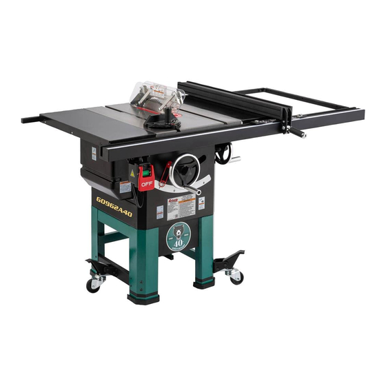
MODEL G0962A40
10" 2 HP OPEN-STAND
HYBRID TABLE SAW
40TH ANNIVERSARY EDITION
OWNER'S MANUAL
(For models manufactured since 07/22)
COPYRIGHT © AUGUST, 2022 BY GRIZZLY INDUSTRIAL, INC.
WARNING: NO PORTION OF THIS MANUAL MAY BE REPRODUCED IN ANY SHAPE
OR FORM WITHOUT THE WRITTEN APPROVAL OF GRIZZLY INDUSTRIAL, INC.
#KS22397 PRINTED IN TAIWAN
V1.08.22
***Keep for Future Reference***
Advertisement
Table of Contents

Related Manuals for Grizzly G0962A40


Summary of Contents for Grizzly G0962A40
- Page 1 (For models manufactured since 07/22) COPYRIGHT © AUGUST, 2022 BY GRIZZLY INDUSTRIAL, INC. WARNING: NO PORTION OF THIS MANUAL MAY BE REPRODUCED IN ANY SHAPE OR FORM WITHOUT THE WRITTEN APPROVAL OF GRIZZLY INDUSTRIAL, INC. #KS22397 PRINTED IN TAIWAN V1.08.22...
- Page 2 This manual provides critical safety instructions on the proper setup, operation, maintenance, and service of this machine/tool. Save this document, refer to it often, and use it to instruct other operators. Failure to read, understand and follow the instructions in this manual may result in fire or serious personal injury—including amputation, electrocution, or death.
-
Page 3: Table Of Contents
Crosscut Sled..........57 SECTION 1: SAFETY ........9 Safety Instructions for Machinery ....9 SECTION AFTERMARKET ACCESSORIES FROM GRIZZLY ....58 Additional Safety for Table Saws ....11 Preventing Kickback ........12 SECTION 7: MAINTENANCE ......61 Protecting Yourself From Kickback....12 Schedule ............ -
Page 4: Introduction
Always consider safety first, as it applies to your individual working conditions. Use this and other machinery with caution and respect. Failure to do so could result in serious personal injury, damage to equip- ment, or poor work results. Model G0962A40 (Mfd. Since 07/22) -
Page 5: Identification
Keep hands out of the line of saw blade. d) Use a push-stick when required. e) Pay particular attention to instructions on reducing risk of kickback. f) Do not perform any operation freehand. g) Never reach around or over saw blade. Model G0962A40 (Mfd. Since 07/22) -
Page 6: Controls & Components
Figure 2. Blade adjustment handwheels and ed) through START button. locks. E. Fence Lock: Locks fence when pushed down, and unlocks fence when pulled up. Figure 1. Location of START/STOP switch. Figure 3. Fence lock handle. Model G0962A40 (Mfd. Since 07/22) -
Page 7: Glossary Of Terms
The following is a list of common definitions, terms and phrases used throughout this manual as they relate to this table saw and woodworking in general. Become familiar with these terms for assembling, adjusting or operating this machine. Your safety is VERY important to us at Grizzly! Arbor: A metal shaft extending from the drive... -
Page 8: Machine Data Sheet
MACHINE DATA SHEET Customer Service #: (570) 546-9663 · To Order Call: (800) 523-4777 · Fax #: (800) 438-5901 MODEL G0962A40 10" 2 HP OPEN‐STAND HYBRID TABLE SAW ‐ 40TH ANNIVERSARY EDITION Product Dimensions: Weight................................243 lbs. Width (side-to-side) x Depth (front-to-back) x Height..............64 x 40-1/2 x 36 in. - Page 9 The information contained herein is deemed accurate as of 8/3/2022 and represents our most recent product specifications. Model G0962A40 PAGE 2 OF 3 Due to our ongoing improvement efforts, this information may not accurately describe items previously purchased. Model G0962A40 (Mfd. Since 07/22)
- Page 10 The information contained herein is deemed accurate as of 8/3/2022 and represents our most recent product specifications. Model G0962A40 PAGE 3 OF 3 Due to our ongoing improvement efforts, this information may not accurately describe items previously purchased. Model G0962A40 (Mfd. Since 07/22)
-
Page 11: Section 1: Safety
Never operate under the influence of drugs or injury or blindness from flying particles. Everyday alcohol, when tired, or when distracted. eyeglasses are NOT approved safety glasses. Model G0962A40 (Mfd. Since 07/22) - Page 12 Make sure they are properly installed, you experience difficulties performing the intend- undamaged, and working correctly BEFORE ed operation, stop using the machine! Contact our operating machine. Technical Support at (570) 546-9663. -10- Model G0962A40 (Mfd. Since 07/22)
-
Page 13: Additional Safety For Table Saws
DO NOT attempt dado or rabbeting operations covered wood products, and some plastics. Never without first reading these sections in this manual. cut materials not intended for this saw. -11- Model G0962A40 (Mfd. Since 07/22) -
Page 14: Preventing Kickback
Making a deep the flying stock, it is often the case that non-through cut will greatly increase the the operator’s hands are pulled into the chance of kickback. blade during kickback. -12- Model G0962A40 (Mfd. Since 07/22) -
Page 15: Section 2: Power Supply
Nominal Voltage ..208V, 220V, 230V, 240V meets the specified circuit requirements. Cycle ............60 Hz Phase ........... Single-Phase Power Supply Circuit ......15 Amps Plug/Receptacle ......NEMA 6-15 -13- Model G0962A40 (Mfd. Since 07/22) - Page 16 The plug must only be inserted into a matching receptacle (see following figure) that is properly installed and grounded in accordance with all local codes and ordinances. -14- Model G0962A40 (Mfd. Since 07/22)
-
Page 17: Converting Voltage To 240V
Close and secure motor junction box. • Wire Cutters/Stripper ........1 Install a NEMA 6-15 plug on power cord, To convert Model G0962A40 to 240V: according to plug manufacturer's instructions. If plug manufacturer's instructions are not DISCONNECT MACHINE FROM POWER! available, NEMA standard 6-15 plug wiring is provided on Page 80. -
Page 18: Section 3: Setup
IMPORTANT: Save all packaging materials until you are completely satisfied with the machine and have resolved any issues between Grizzly or the shipping agent. You MUST have the original pack- aging to file a freight claim. It is also extremely helpful if you need to return your machine later. -
Page 19: Inventory
Hex Wrenches 2.5, 3, 4, 5, 6, 8mm ..1 Ea. M. Handwheels ..........2 N. Foot Lever and Bracket Assemblies ... 2 O. Casters ............3 Figure 8. Model G0962A40 inventory. Motor Cover ..........1 Q. Rear Access Panel ........1 Hardware (Page 18) R. -
Page 20: Hardware Recognition Chart
Hardware Recognition Chart USE THIS CHART TO MATCH UP HARDWARE DURING THE INVENTORY AND ASSEMBLY PROCESS. Flat Head Screw -18- Model G0962A40 (Mfd. Since 07/22) -
Page 21: Cleanup
Figure 9. T23692 Orange Power Degreaser. Repeat Steps 2–3 as necessary until clean, then coat all unpainted surfaces with a quality metal protectant to prevent rust. -19- Model G0962A40 (Mfd. Since 07/22) -
Page 22: Site Considerations
Only install in an Shadows, glare, or strobe effects that may distract access restricted location. or impede the operator must be eliminated. 64" Min. 30" 40½" = Power Connection Figure 10. Minimum working clearances. -20- Model G0962A40 (Mfd. Since 07/22) -
Page 23: Assembly
M8-1.25 x 65 hex bolt and M8-1.25 lock nut (see Figure 12). Figure 14. Caster installed on leg brace. Lever and Bracket Assembly Caster Figure 12. Caster installed on front right leg. -21- Model G0962A40 (Mfd. Since 07/22) - Page 24 M10-1.5 x 25 Figure 16). Lock Washer 10mm Blade Tilt Indicator Flat Washer 10mm Extension Wings Blade Tilt Handwheel Blade Elevation Handwheel Figure 16. Blade tilt indicator and angle scale. Figure 17. Extension wings installed. -22- Model G0962A40 (Mfd. Since 07/22)
- Page 25 Figure 21). Slot Figure 18. Masking tape location for tilting extension wing up. Scale Figure 21. Hex bolt positioned in front fence rail slot. Figure 19. Masking tape location for tilting extension wing down. -23- Model G0962A40 (Mfd. Since 07/22)
- Page 26 Figure 25. Secure outer four cap screws with Figure 23). Do not fully tighten fasteners at M8-1.25 hex nuts. this time. Rear Fence Rail Figure 23. Front fence rail mounted. Figure 25. Mounting rear fence rail. -24- Model G0962A40 (Mfd. Since 07/22)
- Page 27 Fence Lightly in position. Touching Blade Fence Figure 28. Fence scale calibration. 23. Tighten hex nuts from Step 13 to secure front Front fence rail. Fence Rail Figure 27. Fence installed on front rail. -25- Model G0962A40 (Mfd. Since 07/22)
- Page 28 Front Fence Rail Figure 31. Attaching front end of fence rail brace. 31. Re-install end cap and tap screw on right end of fence rail. -26- Model G0962A40 (Mfd. Since 07/22)
-
Page 29: Dust Collection
Figure 35. Dust hose attached to dust port. Handle Tug hose to make sure it does not come off. Note: A tight fit is necessary for proper Miter performance. Gauge Figure 34. Installing miter handle. -27- Model G0962A40 (Mfd. Since 07/22) -
Page 30: Test Run
Blade Tilt Calibration (Page 67). The motor should run smoothly and without Miter Slot to Blade Parallelism (Page 69). unusual noises. Table/Dado Insert Adjustment (Page 76). Insert switch disabling pin through green ON/ START button (see Figure 36). -28- Model G0962A40 (Mfd. Since 07/22) -
Page 31: Section 4: Operations
Read books/magazines or get formal training before beginning any proj- ects. Regardless of the content in this sec- tion, Grizzly Industrial will not be held liable for accidents caused by lack of training. -29- Model G0962A40 (Mfd. Since 07/22) -
Page 32: Disabling & Locking Switch
On the contrary, a workpiece supported on the bowed side will rock during a cut and could cause kickback or severe injury. Figure 38. Minimum lock shaft requirements. -30- Model G0962A40 (Mfd. Since 07/22) -
Page 33: Non-Through & Through Cuts
• Kerf (Tooth) Thickness: 0.094"–0.126" of the riving knife, because the riving knife will be (2.4–3.2mm) higher than the blade. • Riving Knife Thickness: 0.090" (2.3mm) • Blade Size Required for Riving Knife: 10" -31- Model G0962A40 (Mfd. Since 07/22) -
Page 34: Blade Selection
Teeth are arranged in groups • Gullets are small and shallow (similar to a cross-cut blade), then large and deep (similar Flat to a ripping blade Blade Alternate Bevel Figure 41. Ripping blade. Flat Figure 43. Combination blade. -32- Model G0962A40 (Mfd. Since 07/22) - Page 35 Blade Requirements specified in this manual, or unless a thin-kerf riving knife is installed in place of a standard riv- ing knife; otherwise, they will increase the risk of kickback. Figure 45. Stacked dado blade. -33- Model G0962A40 (Mfd. Since 07/22)
-
Page 36: Blade Installation
Use included arbor wrenches to loosen and remove arbor nut, flange, and blade (see Figure 46). Arbor nut has right-hand threads; turn counterclockwise to loosen. Figure 46. Example of removing table saw blade. -34- Model G0962A40 (Mfd. Since 07/22) -
Page 37: Blade Guard Assembly
-35- Model G0962A40 (Mfd. Since 07/22) - Page 38 "Alignment Zone," shown in Figure 52, and will be parallel with blade. Alignment Zone Spreader or Guard Lever Riving Knife Straightedge Blade Figure 50. Example of blade guard installation. Figure 52. Spreader in "Alignment Zone". -36- Model G0962A40 (Mfd. Since 07/22)
- Page 39 Because the blade guard is provided to decrease your risk of injury, it should not be used if it gets in the way of making a safe cut. Use good judgment! -37- Model G0962A40 (Mfd. Since 07/22)
-
Page 40: Riving Knife
Also, use the riving knife for those special opera- Bottom Distance Minimum 3mm tions where the blade guard or its components Maximum 8mm get in the way of safe operation, such as with very narrow cuts. Figure 56. Allowable riving knife clearance. -38- Model G0962A40 (Mfd. Since 07/22) -
Page 41: Ripping
Figure 58, until workpiece is completely beyond saw blade. Keep blade guard installed and in down position. Failure to do this could result in serious personal injury or death. Featherboard Figure 58. Typical ripping operation. -39- Model G0962A40 (Mfd. Since 07/22) -
Page 42: Crosscutting
Crosscutting instructions on this page. Turn saw OFF and allow blade to come to a complete stop before removing cutoff piece. Failure to follow this warning could result in severe lacerations or amputation. -40- Model G0962A40 (Mfd. Since 07/22) -
Page 43: Blade Tilt/Bevel Cuts
Blade Tilt/Bevel Cuts The Model G0962A40 can accommodate dado blades up to 10" in diameter. However, you MUST install the included riving knife while using a 10" diameter dado blade, as it provides a barrier When the blade tilt adjustment bolts are properly... - Page 44 Raise blade up to desired depth of cut (depth of dado channel desired). Cut 3 Fence Workpiece Finished Dado Cut Fence Workpiece Figure 63. Example of dado being cut with multiple light cuts, instead of one deep cut. -42- Model G0962A40 (Mfd. Since 07/22)
-
Page 45: Rabbet Cutting
Cuts 3+ is flat and straight, and make multiple light cuts (rather than one deep cut) to achieve Fence the desired cutting depth. Workpiece Figure 66. Additional single-blade dado cuts. -43- Model G0962A40 (Mfd. Since 07/22) - Page 46 — If workpiece is very tall, or is unstable — If cut is satisfactory, repeat cut with when placed against fence, lay it flat on workpiece. table and use a dado blade to perform rab- bet cut. -44- Model G0962A40 (Mfd. Since 07/22)
-
Page 47: Resawing
Note: To determine the maximum resawing height Blade for this table saw, find the maximum blade height, then double it and subtract ⁄ ". Fence Workpiece Figure 70. Example of second cut to create a rabbet. -45- Model G0962A40 (Mfd. Since 07/22) - Page 48 Power Drill ............1 #8 x 2" Drill Bit ⁄ " ............1 ⁄ " Wood Screw Countersink Drill Bit ..........1 Hex Wrench 5mm ..........1 Ruler ..............1 ⁄ " Assembled Resaw Barrier Figure 71. Resaw barrier. -46- Model G0962A40 (Mfd. Since 07/22)
- Page 49 Note: For additional mounting strength, attach auxiliary board with (6) hex nuts and flat head cap screws using upper and lower T-slots. Figure 74. Example auxiliary fence attached to included fence. 10. Re-install fence cap. -47- Model G0962A40 (Mfd. Since 07/22)
- Page 50 Attach auxiliary fence and set it to desired saw. ALWAYS replace blade guard after width. resawing is complete. Note: When determining correct width, don't forget to account for blade kerf and inaccuracy of fence scale while auxiliary fence is installed. -48- Model G0962A40 (Mfd. Since 07/22)
- Page 51 11. Turn OFF table saw, then separate parts of workpiece and hand plane remaining ridge to remove it. 12. When finished resawing, remove resaw bar- rier and auxiliary fence, then re-install blade guard/spreader or riving knife and standard table insert. -49- Model G0962A40 (Mfd. Since 07/22)
-
Page 52: Section 5: Shop Made Safety Accessories
Step 3 will bend without breaking. Cut a 30º angle at one end of the board. Only Steps 1–3 are required to make a clamp-mounted featherboard. See Page 52 for instructions on clamping. -50- Model G0962A40 (Mfd. Since 07/22) - Page 53 Proceed to Mounting Featherboard in Miter Drill a ⁄ " hole in center of bar, then counter- Slot on Page 52. sink bottom to fit a ⁄ "-20 flat head screw. -51- Model G0962A40 (Mfd. Since 07/22)
- Page 54 The featherboard should be placed firmly enough against the workpiece to keep it against the fence but not so tight that it is difficult to feed the workpiece. -52- Model G0962A40 (Mfd. Since 07/22)
-
Page 55: Push Sticks
⁄ " Grid from the blade! Figure 85. Template for a basic shop-made push stick (not shown at actual size). -53- Model G0962A40 (Mfd. Since 07/22) -
Page 56: Push Blocks
Lip for pushing workpiece ⁄ " Grid 9"−10" Minimum Length Figure 88. Template for a shop-made push block (shown at 50% of full size). -54- Model G0962A40 (Mfd. Since 07/22) -
Page 57: Narrow-Rip Auxiliary Fence & Push Block
Attach handle to base with #8 x 1 ⁄ " wood 3" screws, and attach lip to base with cyanoac- rylate-type wood glue. Length of Table Saw Rip Fence ⁄ " Figure 89. Auxiliary fence dimensions. -55- Model G0962A40 (Mfd. Since 07/22) - Page 58 Turn OFF the saw and allow blade to come ly against table and auxiliary fence (see to a complete stop before removing cut-off Figure 93). piece. Failure to follow this warning could result in serious personal injury. -56- Model G0962A40 (Mfd. Since 07/22)
-
Page 59: Outfeed & Support Tables
Crosscut Sled Support Outfeed Table Table Figure 96. Example of crosscut sled. Figure 95. Example of outfeed & support tables. -57- Model G0962A40 (Mfd. Since 07/22) -
Page 60: Section 6: Aftermarket Accessories From Grizzly
To reduce this risk, only install accessories leave highly polished, finish ready surfaces on recommended for this machine by Grizzly. nearly everything they cut. Made in USA. NOTICE With these all purpose blades for table saws you can rip and crosscut 1"... - Page 61 D4216 Figure 101. Point-of-use dust collectors. T28000—”Bear Crawl” Mobile Base We took years of input and months of testing and design to come out with the Grizzly "Bear Crawl" W1053 Mobile Base. Its 1200 lb. capacity, steel and rub- W1007...
- Page 62 Figure 106. Lined gripping gloves. Figure 104. Heavy-duty roller tables. www.grizzly.com 1-800-523-4777 order online at or call -60- Model G0962A40 (Mfd. Since 07/22)
-
Page 63: Section 7: Maintenance
To reduce risk of shock or accidental startup, always disconnect machine from power before adjustments, Cleaning the Model G0962A40 is relatively easy. maintenance, or service. Vacuum excess wood chips and sawdust, and wipe off the remaining dust with a dry cloth. If any... -
Page 64: Lubrication
Move blade tilt back-and-forth to spread grease (see Figure 108). Front Figure 110. Location of leadscrew. Trunnion Slide Figure 108. Trunnion slide locations. -62- Model G0962A40 (Mfd. Since 07/22) -
Page 65: Section 8: Service
12. Move machine closer to power supply; use shorter extension cord. 13. Centrifugal switch/contact points at fault. 13. Adjust centrifugal switch/clean contact points. Replace either if at fault. 14. Motor or motor bearings at fault. 14. Replace motor. -63- Model G0962A40 (Mfd. Since 07/22) - Page 66 5. Adjust fence parallel with blade (Page 75). 6. Miter slot not parallel with blade. 6. Adjust miter slot parallel with blade (Page 69). 7. Spreader/riving knife not aligned with blade. 7. Align spreader/riving knife with blade (Page 71). -64- Model G0962A40 (Mfd. Since 07/22)
- Page 67 2. Adjust miter slot parallel with blade (Page 69). 3. Adjust fence parallel with blade (Page 75). 3. Fence not parallel with blade. 4. Adjust stop bolts/nuts (Page 67). 4. Stop bolts/nuts out of adjustment. -65- Model G0962A40 (Mfd. Since 07/22)
- Page 68 1. Rip fence mounted/adjusted incorrectly. 1. Remount rip fence. Adjust fence to ensure does not move adjustment screws are not too tight (Page 74). smoothly. 2. Rails dirty or sticky. 2. Clean and wax rails. -66- Model G0962A40 (Mfd. Since 07/22)
-
Page 69: Blade Tilt Calibration
Figure 111. Make sure a blade tooth does not obstruct placement of square. Leadscrew Blade 90° Square Table Figure 113. Location of 90° stop nuts. Figure 111. Checking blade at 90°. -67- Model G0962A40 (Mfd. Since 07/22) - Page 70 Make sure tilt indicator arrow points to 45° mark on scale. If it does not, adjust indicator Figure 114. Checking blade at 45°. arrow as described on Page 67. -68- Model G0962A40 (Mfd. Since 07/22)
-
Page 71: Miter Slot To Blade Parallelism
— If blade tip does not touch end of adjust- able square similar to first measurement, table will need to be adjusted. Proceed to Blade tilted to 0º Step 6. Front Figure 116. Example of adjusting blade to miter slot. -69- Model G0962A40 (Mfd. Since 07/22) - Page 72 45°, one end of table will need to be shimmed higher with metal shim stock. Continue to Step 9. Loosen (4) table mounting bolts from Step 6. Figure 120. Shim procedure diagram B. -70- Model G0962A40 (Mfd. Since 07/22)
-
Page 73: Spreader Or Riving Knife Alignment
"Alignment Zone," as shown in Figure 122. Top Alignment Bottom Alignment Figure 121. Checking top and bottom riving knife parallelism with blade. -71- Model G0962A40 (Mfd. Since 07/22) - Page 74 Remove table insert, but leave Phillips head — If you cannot straighten spreader/riving screws mounted in table throat. knife properly, replace it. Note: Table insert is held in place by a magnet. -72- Model G0962A40 (Mfd. Since 07/22)
-
Page 75: Adjusting Fence
Figure 125. (Side View) Fence " Gap Front Set Table Rear Screws Bearing (1 of 2) Shaft Figure 125. Fence height is adjusted by two front set screws and rear bearing shaft. -73- Model G0962A40 (Mfd. Since 07/22) - Page 76 Tighten knurled lock nut. Re-install fence and check clamping pres- Roller sure of lock handle. Bearing Repeat Steps 1–5 as necessary until desired results are achieved. Outer Jam Nut Figure 128. Rear adjustment area for leveling fence. -74- Model G0962A40 (Mfd. Since 07/22)
-
Page 77: Calibrating Fence To Blade
Fence is Fence Blade Parallel to Miter Slot, which is Parallel to Blade Figure 131. Checking fence parallelism w/blade. -75- Model G0962A40 (Mfd. Since 07/22) -
Page 78: Fence Scale Calibration
Reposition and lock fence at 12", as indicated by the scale. Flip over your scrap piece of wood, placing side that was cut in Step 1 against fence, then make your cut. Figure 134. Adjustment screws location. -76- Model G0962A40 (Mfd. Since 07/22) -
Page 79: Calibrating Miter Gauge
Figure 137, adjust indicator so it points to 90°, then tighten screw to secure. Stop Pin Knob Figure 135. Miter gauge adjustment components. Indicator Figure 137. Location of angle indicator and Phillips head screw. -77- Model G0962A40 (Mfd. Since 07/22) -
Page 80: Belt Tension & Replacement
Set blade to 0° on tilt scale, then raise or lower blade to approximately 2" above table. Loosen blade tension hex bolt shown in Figure 138. Blade Tension Hex Bolt Motor Belt Figure 138. Components used to tension or remove belt. -78- Model G0962A40 (Mfd. Since 07/22) -
Page 81: Section 9: Wiring
Technical Support at (570) 546-9663. The photos and diagrams included in this section are best viewed in color. You can view these pages in color at www.grizzly.com. -79- Model G0962A40 (Mfd. Since 07/22) -
Page 82: Wiring Diagram
(Pre-wired for 120V) Ground Run Capacitor CBB60 30µF 350VAC Start Capacitor CD60 200µF 250VAC Motor (Re-wired for 240V) Ground Run Capacitor CBB60 30µF 350VAC Start Capacitor CD60 200µF 250VAC READ ELECTRICAL SAFETY -80- Model G0962A40 (Mfd. Since 07/22) ON PAGE 79! -
Page 83: Electrical Components
Electrical Components Figure 139. START/STOP switch wiring. Figure 141. Junction box motor wiring at 120V. Figure 140. Run and start capacitors. Figure 142. Motor wiring label inside junction box. READ ELECTRICAL SAFETY -81- Model G0962A40 (Mfd. Since 07/22) ON PAGE 79! -
Page 84: Section 10: Parts
SECTION 10: PARTS We do our best to stock replacement parts when possible, but we cannot guarantee that all parts shown are available for purchase. Call (800) 523-4777 or visit www.grizzly.com/parts to check for availability. Main 29-4 29-1 29-7 29-8... - Page 85 123 P0962A40123 CAP SCREW M5-.8 X 10 P0962A40065 HEX NUT M5-.8 124 P0962A40124 DADO TABLE INSERT P0962A40066 CAP SCREW M5-.8 X 10 125 P0962A40125 HEX WRENCH 2.5MM BUY PARTS ONLINE AT GRIZZLY.COM! -83- Model G0962A40 (Mfd. Since 07/22) Scan QR code to visit our Parts Store.
-
Page 86: Cabinet & Stand
HEX BOLT M8-1.25 X 65 P0962A40241 HEX NUT M5-.8 P0962A40221 LOCK NUT M8-1.25 P0962A40242 STAND, 1-PIECE WELDED P0962A40222 FLAT WASHER 8MM P0962A40244 HEX NUT M3-.5 BUY PARTS ONLINE AT GRIZZLY.COM! -84- Model G0962A40 (Mfd. Since 07/22) Scan QR code to visit our Parts Store. -
Page 87: Fence & Rails
300-33 P0962A40300-33 LOCK NUT M10-1.5 P0962A40361 INT TOOTH WASHER 5MM 300-34 P0962A40300-34 HEX BOLT M6-1 X 40 P0962A40364 ADJUSTABLE CABLE CLAMP 300-35 P0962A40300-35 SPRING PLATE BUY PARTS ONLINE AT GRIZZLY.COM! -85- Model G0962A40 (Mfd. Since 07/22) Scan QR code to visit our Parts Store. -
Page 88: Blade Guard
CAP SCREW M5-.8 X 30 P0962A40411 GUARD RAIL FRONT WINDOW P0962A40426 BLADE GUARD WINDOW COVER P0962A40412 PHLP HD SCR M5-.8 X 25 BUY PARTS ONLINE AT GRIZZLY.COM! -86- Model G0962A40 (Mfd. Since 07/22) Scan QR code to visit our Parts Store. -
Page 89: Miter Gauge
PHLP HD SCR M4-.7 X 10 P0962A40512 MITER HANDLE P0962A40529 PHLP HD SCR M4-.7 X 6 P0962A40513 RIVET 2 X 5MM BUY PARTS ONLINE AT GRIZZLY.COM! -87- Model G0962A40 (Mfd. Since 07/22) Scan QR code to visit our Parts Store. -
Page 90: Labels & Cosmetics
Safety labels help reduce the risk of serious injury caused by machine hazards. If any label comes off or becomes unreadable, the owner of this machine MUST replace it in the original location before resuming operations. For replacements, contact (800) 523-4777 or www.grizzly.com. BUY PARTS ONLINE AT GRIZZLY.COM! -88- Model G0962A40 (Mfd. -
Page 91: Warranty & Returns
WARRANTY & RETURNS Grizzly Industrial, Inc. warrants every product it sells for a period of 1 year to the original purchaser from the date of purchase. This warranty does not apply to defects due directly or indirectly to misuse, abuse, negligence, accidents, repairs or alterations or lack of maintenance.
Need help?
Do you have a question about the G0962A40 and is the answer not in the manual?
Questions and answers
How to install the riving knife
To install the riving knife on a Grizzly G0962A40:
1. Disconnect the machine from power to prevent accidental startup.
2. Align the riving knife properly with the blade to ensure safe operation.
3. Follow the instructions on Page 71 of the manual for proper riving knife alignment.
The riving knife functions as a spreader to prevent workpieces from pinching the blade and causing kickback.
This answer is automatically generated