Table of Contents
Advertisement
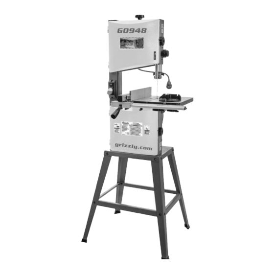
MODEL G0948
10" 1/2 HP BANDSAW
OWNER'S MANUAL
(For models manufactured since 08/21)
COPYRIGHT © SEPTEMBER, 2021 BY GRIZZLY INDUSTRIAL, INC.
WARNING: NO PORTION OF THIS MANUAL MAY BE REPRODUCED IN ANY SHAPE
OR FORM WITHOUT THE WRITTEN APPROVAL OF GRIZZLY INDUSTRIAL, INC.
#MN22059 PRINTED IN CHINA
V1.09.21
Advertisement
Table of Contents

Subscribe to Our Youtube Channel
Related Manuals for Grizzly G0948


Summary of Contents for Grizzly G0948
- Page 1 (For models manufactured since 08/21) COPYRIGHT © SEPTEMBER, 2021 BY GRIZZLY INDUSTRIAL, INC. WARNING: NO PORTION OF THIS MANUAL MAY BE REPRODUCED IN ANY SHAPE OR FORM WITHOUT THE WRITTEN APPROVAL OF GRIZZLY INDUSTRIAL, INC. #MN22059 PRINTED IN CHINA V1.09.21...
- Page 2 This manual provides critical safety instructions on the proper setup, operation, maintenance, and service of this machine/tool. Save this document, refer to it often, and use it to instruct other operators. Failure to read, understand and follow the instructions in this manual may result in fire or serious personal injury—including amputation, electrocution, or death.
-
Page 3: Table Of Contents
Table of Contents INTRODUCTION ..........2 SECTION 5: ACCESSORIES ......44 Contact Info............ 2 SECTION 6: MAINTENANCE ......47 Manual Accuracy ........... 2 Schedule ............47 Identification ........... 3 Cleaning & Lubricating ......... 47 Controls & Components ......... 4 Machine Data Sheet ........6 SECTION 7: SERVICE ........ -
Page 4: Introduction
ID label (see below). This information is required for us to provide proper tech support, and it helps us determine if updated documentation is available for your machine. Manufacture Date Serial Number Model G0948 (Mfd. Since 08/21) -
Page 5: Identification
Do not remove jammed cutoff pieces until blade has stopped. Maintain proper adjustment of blade tension, blade guides, and thrust bearings. d) Adjust upper blade guide to just clear workpiece. Hold workpiece firmly against table. Model G0948 (Mfd. Since 08/21) -
Page 6: Controls & Components
Can be adjusted from 0°–60° left or right. B. LED Work Light ON/OFF Switch: Turns light ON and OFF. Illuminates cutting area for E. Miter Gauge Lock Knob: Secures angle better visibility. position of miter gauge. Fence Lock Handle: Secures fence position. Model G0948 (Mfd. Since 08/21) - Page 7 Trunnion w/Table Tilt Scale: Functions as a tilting base for table. Graduated in degrees from 0°–45° for setting bevel angle. K. Table Tilt Lock Lever: Secures table tilt angle setting. Table Tilt Indicator: Shows angle of table tilt. Model G0948 (Mfd. Since 08/21)
-
Page 8: Machine Data Sheet
MACHINE DATA SHEET Customer Service #: (570) 546-9663 · To Order Call: (800) 523-4777 · Fax #: (800) 438-5901 MODEL G0948 10" 1/2 HP BANDSAW Product Dimensions: Weight................................69 lbs. Width (side-to-side) x Depth (front-to-back) x Height............... 28 x 21-1/2 x 58-1/2 in. - Page 9 The information contained herein is deemed accurate as of 9/22/2021 and represents our most recent product specifications. Model G0948 PAGE 2 OF 2 Due to our ongoing improvement efforts, this information may not accurately describe items previously purchased. Model G0948 (Mfd. Since 08/21)
-
Page 10: Section 1: Safety
Never operate under the influence of drugs or injury or blindness from flying particles. Everyday alcohol, when tired, or when distracted. eyeglasses are NOT approved safety glasses. Model G0948 (Mfd. Since 08/21) - Page 11 Make sure they are properly installed, you experience difficulties performing the intend- undamaged, and working correctly BEFORE ed operation, stop using the machine! Contact our operating machine. Technical Support at (570) 546-9663. Model G0948 (Mfd. Since 08/21)
-
Page 12: Additional Safety For Bandsaws
DO NOT try to stop or slow blade with your This machine is NOT designed to cut metal, hand or the workpiece. glass, stone, tile, etc. -10- Model G0948 (Mfd. Since 08/21) -
Page 13: Section 2: Power Supply
-11- Model G0948 (Mfd. Since 08/21) - Page 14 Two-prong outlets do not meet the grounding requirements for this machine. Do not modify or use an adapter on the plug provided—if it will not fit the outlet, have a qualified electrician install the proper outlet with a verified ground. -12- Model G0948 (Mfd. Since 08/21)
-
Page 15: Section 3: Setup
IMPORTANT: Save all packaging materials until you are completely satisfied with the machine and have resolved any issues between Grizzly or the shipping agent. You MUST have the original pack- aging to file a freight claim. It is also extremely Wear safety glasses during helpful if you need to return your machine later. -
Page 16: Inventory
H. Open-End Wrench 10 x 13mm ....1 Hex Wrenches 3, 4, 5, 6mm ....1 Ea. Rubber Feet ..........4 K. Stand Braces (Long) ........2 L. Stand Braces (Short) ........2 M. Stand Legs ..........4 -14- Model G0948 (Mfd. Since 08/21) -
Page 17: Hardware Recognition Chart
Hardware Recognition Chart USE THIS CHART TO MATCH UP HARDWARE DURING THE INVENTORY AND ASSEMBLY PROCESS. Flat Head Screw -15- Model G0948 (Mfd. Since 08/21) -
Page 18: Site Considerations
Figure 11. Rubber feet attached to stand legs. Children and visitors may be seriously injured if unsuper- vised around this machine. Lock entrances to the shop or disable start switch or power connection to prevent unsupervised use. -16- Model G0948 (Mfd. Since 08/21) - Page 19 Step 7 (see Figure 15). Long Brace Shoulder Screw (1 of 2) (1 of 2) Figure 13. Leg assemblies attached with long braces. Scale Indicator Figure 15. Table attached to trunnions. -17- Model G0948 (Mfd. Since 08/21)
- Page 20 15 on Page 17), set indicator to "0", and tighten screw. 12. Attach fence rail to front of table with (4) M8-1.25 x 18 wing bolts (see Figure 17). Fence Rail Wing Bolts Figure 17. Fence rail attached to front of table. -18- Model G0948 (Mfd. Since 08/21)
-
Page 21: Dust Collection
Hose Clamp Dust Hose Figure 19. Example of 2" dust hose attached to dust port. Gently pull hose to make sure it does not come off. A tight fit is necessary for proper performance. -19- Model G0948 (Mfd. Since 08/21) -
Page 22: Initial Blade Tracking
(refer to Aligning Wheels on Page 53 for detailed instruc- The wheels on the G0948 were aligned at the fac- tions on adjusting the tracking). tory, so center tracking is the only adjustment that needs to be performed when the saw is new. -
Page 23: Test Run
Serious injury or death can result from tensioned. using this machine BEFORE understanding its controls and related safety information. DO NOT operate, or allow others to operate, machine until the information is understood. -21- Model G0948 (Mfd. Since 08/21) -
Page 24: Tensioning Blade
— If the machine does start, immediately stop the machine. The switch is not work- ing correctly. This safety feature must work properly before proceeding with regular operations. Call Tech Support for help. -22- Model G0948 (Mfd. Since 08/21) - Page 25 Blade Guide Bearings on Pages 24–25. the blade incrementally and repeat Step 5 until properly tensioned. Adjust blade guides as described in Adjusting Blade Support Bearings and Adjusting Blade Guide Bearings on Pages 24–25. -23- Model G0948 (Mfd. Since 08/21)
-
Page 26: Adjusting Blade Support Bearings
Tighten button head cap screw loosened in will contact (and ruin) the "tooth set" of the Step 2. blade during cutting operations. -24- Model G0948 (Mfd. Since 08/21) -
Page 27: Adjusting Blade Guide Bearings
(see Page 24 for reference). BladeThickness “Tooth Set” Wider Than Blade Thickness Guide Bearing Figure 29. Illustration of blade "tooth set". Guide Block Cap Screw Adjustment Knob (1 of 2) Figure 27. Upper guide bearing components. -25- Model G0948 (Mfd. Since 08/21) - Page 28 Guide Bearing Guide Block Screw (1 of 2) Cap Screw Figure 31. Lower blade guide components (table removed for clarity). Tighten screws to secure settings. Re-check setting after tightening. -26- Model G0948 (Mfd. Since 08/21)
-
Page 29: Aligning Table
Step 3. Miter Slot Blade Square Figure 32. Example of placing a straightedge along blade and measuring to miter slot. Table Figure 34. Squaring back of blade and table. -27- Model G0948 (Mfd. Since 08/21) -
Page 30: Aligning Fence
Figure 35. Location of fence adjustment cap screws. Item(s) Needed Hex Wrench 4mm ..........1 To align fence: DISCONNECT MACHINE FROM POWER! Make sure table is aligned with blade (see Adjusting Miter Slot Parallelism on Page 27 for instructions). -28- Model G0948 (Mfd. Since 08/21) -
Page 31: Calibrating Miter Gauge
— If square does not rest flush and evenly adjust pointer to 0° mark on scale, then against both miter gauge face and side of tighten screw to secure setting. blade, the miter gauge must be calibrated. Proceed to Step 3. -29- Model G0948 (Mfd. Since 08/21) -
Page 32: Section 4: Operations
Read books/magazines or get formal training before beginning any proj- ects. Regardless of the content in this sec- tion, Grizzly Industrial will not be held liable for accidents caused by lack of training. -30- Model G0948 (Mfd. Since 08/21) -
Page 33: Basic Functions Of A Bandsaw
On the contrary, a workpiece supported on the bowed side will rock during a cut and could cause kickback or severe injury. -31- Model G0948 (Mfd. Since 08/21) -
Page 34: Setting Upper Blade Guide Height
Loosen table tilt lock lever (see Figure 38). guide post so that blade guide assembly just clears (no more than ⁄ ") workpiece. Tilt table to desired angle, then tighten lock lever. Tighten guide post lock knob to secure setting. -32- Model G0948 (Mfd. Since 08/21) - Page 35 0°, follow Steps 1–5 for the tilt scale and make sure positive stop bolt is desired angle. correctly calibrated. Loosen screw on table tilt scale indicator, align pointer with zero on scale, then tighten screw. -33- Model G0948 (Mfd. Since 08/21)
-
Page 36: Choosing Blades
Straight Cutting: Use the largest width TPI: The number of teeth per inch measured blade that you own. Large blades excel at from gullet to gullet. cutting straight lines and are less prone to wander. -34- Model G0948 (Mfd. Since 08/21) - Page 37 The raker set is ideal for most con- and the gullets are usually rounded for easier tour cuts. waste removal. These blades are excellent for the tough demands of resawing and rip- ping thick material. -35- Model G0948 (Mfd. Since 08/21)
- Page 38 High-Speed Steel blades, providing superior edge-holding charac- teristics (see Figure 45). Figure 46. Bi-metal blade composition. Carbon Steel Carbide Impregnated Steel Figure 45. Carbide-tooth blade composition. -36- Model G0948 (Mfd. Since 08/21)
-
Page 39: Blade Selection Chart
Crosscutting Thick Stock Crosscutting Round Stock Miter Cut Tenons Sharp Curves Gradual Curves Tooth Type Tooth Pitch (Teeth Per Inch or TPI) Fine Medium Coarse Hook Raker Skip (14-32 TPI) (4-12 TPI) (2-4 TPI) -37- Model G0948 (Mfd. Since 08/21) -
Page 40: Blade Care & Break-In
• Using the wrong pitch (TPI) for the workpiece cut. thickness. The general rule of thumb is to have no less than two teeth in contact with the workpiece at all times during cutting. -38- Model G0948 (Mfd. Since 08/21) -
Page 41: Removing/Installing Blade
Guide Bearings on Pages 24–25). Put on heavy leather gloves. Close wheel covers, and install table insert and fence rail. Make sure fence is parallel to miter slot and, if necessary, adjust alignment (see Page 28). -39- Model G0948 (Mfd. Since 08/21) -
Page 42: Changing Blade Speed
V-belt (see Figure 49). Blade Speed Wheel Pulley The Model G0948 offers blade speeds of 1520 and 2620 FPM. Speed changes are made by re- positioning the V-belt in different pulley grooves. Belt Keep in mind, cutting results are not just related to blade speed. -
Page 43: Ripping
Figure 53. Example of a crosscutting operation with the miter gauge. NEVER place fingers or hands in the line of cut. If you slip, your hands or fingers may go into the blade and may be cut. -41- Model G0948 (Mfd. Since 08/21) -
Page 44: Resawing
When resawing thin pieces, a wandering blade (blade lead) can tear through the side of the workpiece, exposing your hands to the blade teeth. Always use push blocks when resawing and keep your hands clear of the blade. -42- Model G0948 (Mfd. Since 08/21) -
Page 45: Stacked Cuts
(Be careful not to cut into the brads or you may break the blade!) Lay out the shape you intend to cut on face of top piece. Figure 55. Example of a stacked cut setup. -43- Model G0948 (Mfd. Since 08/21) -
Page 46: Section 5: Accessories
T20451—“Kirova” Clear Safety Glasses To reduce this risk, only install accessories T20452—“Kirova” Anti-Reflective S. Glasses recommended for this machine by Grizzly. T20456—DAKURA Safety Glasses NOTICE T20502 Refer to our website or latest catalog for additional recommended accessories. - Page 47 Measures 3' wide x 5' long x ⁄ " thick. Figure 59. The Missing Shop Manual: Bandsaw. Figure 61. T10456 Anti-Fatigue Mat. www.grizzly.com 1-800-523-4777 order online at or call -45- Model G0948 (Mfd. Since 08/21)
- Page 48 Features thumb roll and stainless steel construc- tion. Range: 0-6", 0-150mm. Resolution: 0.0005", ⁄ ". 0.01mm, Figure 64. T32407 Grip Snap-Ring Plier Set. Figure 63. H7978 6" Fractional Digital Caliper. www.grizzly.com 1-800-523-4777 order online at or call -46- Model G0948 (Mfd. Since 08/21)
-
Page 49: Section 6: Maintenance
Remove blade and thoroughly clean all built- up sawdust from the rubber tires on the wheels. Figure 65. Model G4682 Dry Coating Lube. • Clean/vacuum dust buildup from inside cabi- net and off motor. -47- Model G0948 (Mfd. Since 08/21) -
Page 50: Section 7: Service
12. Move machine closer to power supply; use shorter extension cord (Page 12). 13. Centrifugal switch/contact points at fault. 13. Adjust centrifugal switch/clean contact points. Replace either if at fault. 14 Motor or motor bearings at fault. 14. Replace motor. -48- Model G0948 (Mfd. Since 08/21) - Page 51 5. Blade has missing/bent teeth or faulty weld. 5. Replace blade (Page 39). Gullets loaded 1. Excessive feed rate/pressure. 1. Reduce feed rate/pressure. with chips. 2. Install correct blade (Page 34). 2. Blade TPI is too fine. -49- Model G0948 (Mfd. Since 08/21)
- Page 52 2. Clean dust port. 3. Low CFM (airflow) from dust collection 3. Inspect ducting for leaks/clogs and repair as system. necessary; move dust collector closer to machine; install a stronger dust collector (Page 19). -50- Model G0948 (Mfd. Since 08/21)
-
Page 53: Checking/Adjusting Belt Tension
Figure 66, and noting how much it moves. deflection in belt. — If belt is not properly tensioned, per- Close wheel cover. Adjusting Belt Tension form procedure. Wheel Pulley Approximately " Deflection Motor Pulley Figure 66. Checking belt tension. -51- Model G0948 (Mfd. Since 08/21) -
Page 54: Replacing Belt
Pivot motor to the right (as viewed from back (see Pages 20 & 22), and adjust support of bandsaw) to release belt tension. bearings and guide bearings (see Pages 24–25). Open lower wheel cover and remove belt from motor pulley. -52- Model G0948 (Mfd. Since 08/21) -
Page 55: Aligning Wheels
Use upper wheel: Adjust Figure 69. Example of checking if wheels are blade tracking knob rear adjustment set coplanar. to tilt upper wheel. bolts to tilt lower wheel left/right. Figure 70. Wheel alignment illustration. -53- Model G0948 (Mfd. Since 08/21) - Page 56 Figure 72. Location of rear lateral adjustment Remove blade. components. Remove wheel to be shimmed. Place as many shims as necessary to correct gap measured in Step 3 onto wheel shaft. -54- Model G0948 (Mfd. Since 08/21)
- Page 57 Note: Marking the wheels ensures more accurate results in case there are irregulari- ties in the wheels. Upper Wheel Straightedge Straightedge Lower Wheel Figure 73. Example of using a straightedge to check lateral wheel alignment. -55- Model G0948 (Mfd. Since 08/21)
-
Page 58: Blade Lead
(see Aligning Table and Aligning Fence procedures for detailed information). Perform test cut with bandsaw. — If there is still blade lead present, com- pensate for this condition by skewing the fence, as instructed in the following procedures. -56- Model G0948 (Mfd. Since 08/21) -
Page 59: Adjusting Wheel Brush
Adjust wheel brush so it makes firm, even contact with wheel without bending the bris- tles, then tighten acorn nut to secure wheel Acorn brush in place. Wheel Brush Figure 76. Location of wheel brush. -57- Model G0948 (Mfd. Since 08/21) -
Page 60: Section 8: Wiring
Technical Support at (570) 546-9663. The photos and diagrams included in this section are best viewed in color. You can view these pages in color at www.grizzly.com. -58- Model G0948 (Mfd. Since 08/21) -
Page 61: Wiring Diagram
E337681 Light Switch DKLD AN-18 250V 6A ON/OFF Switch DKLD AN17 125V 20A Ground Ground Neutral 120V Motor Start Capacitor Ground CBB60 35uF 350VAC 120VAC Ground 5-15 Plug READ ELECTRICAL SAFETY -59- Model G0948 (Mfd. Since 08/21) ON PAGE 58! -
Page 62: Electrical Components
Electrical Components LED Driver Start Capacitor Figure 78. Start capacitor wiring. Power ON/OFF Switch LED Light ON/OFF Switch Figure 77. ON/OFF switch wiring. Figure 79. Work light wiring. READ ELECTRICAL SAFETY -60- Model G0948 (Mfd. Since 08/21) ON PAGE 58! -
Page 63: Section 9: Parts
SECTION 9: PARTS We do our best to stock replacement parts when possible, but we cannot guarantee that all parts shown are available for purchase. Call (800) 523-4777 or visit www.grizzly.com/parts to check for availability. Main 29 28 90 89... - Page 64 P0948102 HEX BOLT M6-1 X 20 P0948051 HEX NUT M8-1.25 P0948103 SET SCREW M6-1 X 8 P0948052 KNOB COVER P0948104 MOTOR PULLEY BUY PARTS ONLINE AT GRIZZLY.COM! -62- Model G0948 (Mfd. Since 08/21) Scan QR code to visit our Parts Store.
- Page 65 LOCK WASHER 5MM P0948137 HEX NUT M5-.8 P0948178 TRUNNION (FRONT) P0948138 FLAT WASHER 5MM P0948179 PUSH STICK P0948139 CORD CLAMP 3/8" BUY PARTS ONLINE AT GRIZZLY.COM! -63- Model G0948 (Mfd. Since 08/21) Scan QR code to visit our Parts Store.
-
Page 66: Labels & Cosmetics
Safety labels help reduce the risk of serious injury caused by machine hazards. If any label comes off or becomes unreadable, the owner of this machine MUST replace it in the original location before resuming operations. For replacements, contact (800) 523-4777 or www.grizzly.com. BUY PARTS ONLINE AT GRIZZLY.COM! -64- Model G0948 (Mfd. -
Page 67: Warranty & Returns
WARRANTY & RETURNS Grizzly Industrial, Inc. warrants every product it sells for a period of 1 year to the original purchaser from the date of purchase. This warranty does not apply to defects due directly or indirectly to misuse, abuse, negligence, accidents, repairs or alterations or lack of maintenance.
Need help?
Do you have a question about the G0948 and is the answer not in the manual?
Questions and answers