Table of Contents
Advertisement
Quick Links
For questions or help with this product contact Tech Support at (570) 546-9663 or techsupport@grizzly.com
The following changes were made since the owner's manual was printed:
•
Blade guard changed.
•
Model G0605X1/G0606X1 extension tables now ship in Carton #1.
Aside from this information, all other content in the owner's manual applies and MUST be read and under-
stood for your own safety. IMPORTANT: Keep this update with the owner's manual for future reference.
For questions or help, contact our Tech Support at (570) 546-9663 or techsupport@grizzly.com.
Revised G0605X1 Specifications
Shipping Dimensions:
Carton #1
Content ........................................................................................... Machine & Extension Tables
Weight.............................................................................................................................. 785 lbs.
Length x Width x Height ...................................................................................... 46 x 43 x 42 in.
Revised G0606X1 Specifications
Shipping Dimensions:
Carton #1
Content ........................................................................................... Machine & Extension Tables
Weight.............................................................................................................................. 783 lbs.
Length x Width x Height ...................................................................................... 46 x 43 x 42 in.
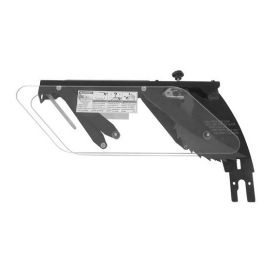
New Blade Guard (V4)
WARNING: NO PORTION OF THIS MANUAL MAY BE REPRODUCED IN ANY SHAPE
OR FORM WITHOUT THE WRITTEN APPROVAL OF GRIZZLY INDUSTRIAL, INC.
READ THIS FIRST
COPYRIGHT © MAY, 2021 BY GRIZZLY INDUSTRIAL, INC.
#CS21910 PRINTED IN TAIWAN
Model G0605X1, G0606X1,
G0696X, G0967X
***IMPORTANT UPDATE***
For Machines Mfd. Since 07/21
and Owner's Manual Revised 10/14
Old Blade Guard (V3)
Advertisement
Table of Contents

Related Manuals for Grizzly G0967X


Summary of Contents for Grizzly G0967X
- Page 1 ***IMPORTANT UPDATE*** For Machines Mfd. Since 07/21 and Owner's Manual Revised 10/14 For questions or help with this product contact Tech Support at (570) 546-9663 or techsupport@grizzly.com The following changes were made since the owner's manual was printed: • Blade guard changed.
- Page 2 Revised Blade Guard Parts 200V4-33 200V4-3 200V4-5 200V4-1 200V4-6 200V4-13 200V4-2 200V4-14 200V4-13 200V4-3 200V4-34 200V4-15 200V4-8 200V4-16 200V4-7 200V4-6 200V4-17 200V4-3 200V4-7 200V4-7 200V4-8 200V4-18 200V4-18 200V4-8 200V4 200V4-1 200V4-19 200V4-1 200V4-4 200V4-20 200V4-6 200V4-5 200V4-3 200V4-9 200V4-3 200V4-10 200V4-6 200V4-7 200V4-12...
- Page 3 For Machines Mfd. Since 07/16 and Owner's Manual Revised 10/14 For questions or help with this product contact Tech Support at (570) 546-9663 or techsupport@grizzly.com The following changes were recently made to this machine since the owner's manual was printed: •...
- Page 4 G0605X1/G0696X Wiring 220V, 1-Ph Power Junction Box L6-30 Plug (As Recommended) Ground R/1/L1 S/3/L2 T/5/L3 Ground 220 VAC MA-30 220V Magnetic Switch U/2/T1 V/4/T2 W/6/T3 Assembly MPE-30 SDE RA-30 Digital Readout Installation work and electrical wiring must be done by qualified electrician in accordance with all applicable codes...
- Page 5 G0606X1/G0697X Wiring 220V, 3-Ph Power Junction Box Ground 220 VAC L15-30 PLUG (as recommended) PHASE CONVERTER Ground If connecting machine to a phase converter, the manufactured leg must be connected to terminal L3. R/1/L1 S/3/L2 T/5/L3 NO13 MA-18 NC21 NC22 220V U/2/T1 V/4/T2...
- Page 6 G0606X1/G0697X Wiring 440V, 3-Ph Power Junction Box Ground 3-PHASE 440 VAC DISCONNECT SWITCH (as recommended ) Ground R/1/L1 S/3/L2 T/5/L3 NO13 MA-18 NC21 NC22 220V U/2/T1 V/4/T2 W/6/T3 NO14 SDE RA-30 Magnetic Digital Readout Switch Assembly MPE-30 On/Off Switch Ground Angle Sensor V2 U2 Motor@440V 3-Ph...
- Page 7 ***IMPORTANT UPDATE*** For Machines Mfd. Since 11/19 and Owner's Manual Revised 10/14 For questions or help with this product contact Tech Support at (570) 546-9663 or techsupport@grizzly.com The following changes were recently made since the owner's manual was printed: •...
- Page 8 ***IMPORTANT UPDATE*** For Machines Mfd. Since 2/19 and Owner's Manual Revised 10/14 For questions or help with this product contact Tech Support at (570) 546-9663 or techsupport@grizzly.com The following change was recently made since the owner's manual was printed: •...
- Page 9 New Blade Guard Parts 200V3 200V3-1 200V3-2 200V3-3 200V3-4 200V3-5 200V3-6 200V3-33 200V3-7 200V3-14 200V3-13 200V3-20 200V3-15 200V3-8 200V3-16 200V3-6 200V3-7 200V3-17 200V3-3 200V3-7 200V3-18 200V3-8 200V3-18 200V3-5 200V3-9 200V3-19 200V3-11 200V3-4 200V3-1 200V3-3 200V3-3 200V3-10 200V3-6 200V3-7 200V3-22 200V3-8 200V3-23 200V3-5 200V3-12...
- Page 10 ***IMPORTANT UPDATE*** For Machines Mfd. Since 11/17 and Owner's Manual Revised 10/14 For questions or help with this product contact Tech Support at (570) 546-9663 or techsupport@grizzly.com The following change was recently made since the owner's manual was printed: •...
- Page 11 Model G0697X Model G0606X1 175370 COPYRIGHT © FEBRUARY, 2009 BY GRIZZLY INDUSTRIAL, INC. REVISED OCTOBER, 2014 (WK) WARNING: NO PORTION OF THIS MANUAL MAY BE REPRODUCED IN ANY SHAPE OR FORM WITHOUT THE WRITTEN APPROVAL OF GRIZZLY INDUSTRIAL, INC. (FOR MODELS MANUFACTURED SINCE 8/11) #BL11524 PRINTED IN TAIWAN...
- Page 12 This manual provides critical safety instructions on the proper setup, operation, maintenance, and service of this machine/tool. Save this document, refer to it often, and use it to instruct other operators. Failure to read, understand and follow the instructions in this manual may result in fire or serious personal injury—including amputation, electrocution, or death.
-
Page 13: Table Of Contents
Table of Contents INTRODUCTION ..........2 SECTION SHOP MADE SAFETY Manual Accuracy ........... 2 ACCESSORIES ..........50 Contact Info............ 2 Featherboards ..........50 Machine Description ........2 Push Sticks ..........53 Identification ........... 3 Push Blocks ..........54 Machine Data Sheets ........4 Narrow-Rip Auxiliary Fence &... -
Page 14: Introduction
This will help us help you faster. contained inside. Sometimes we make mistakes, but our policy of continuous improvement also Grizzly Technical Support means that sometimes the machine you receive 1203 Lycoming Mall Circle will be slightly different than what is shown in Muncy, PA 17756 the manual. -
Page 15: Identification
Identification Miter Blade Guard & Gauge Outfeed Spreader Fence Front Table Scale Extension Front Rail Fence Lock Fence Indicator Table Tube Handle On/Off Switch Front Rail Switch Disabling Lock Support Motor Cover Blade Tilt Scale Blade Angle Blade Tilt Blade Height Digital Readout Handwheel &... - Page 16 MODEL G0605X1/G0606X1/G0696X/G0697X 12" LEFT-TILTING TABLE SAWS Model Number G0605X1 G0606X1 G0696X G0697X Motor 5 HP, 220V, 1-Ph ⁄ HP, 220V/440V, 5 HP, 220V, 1-Ph ⁄ HP, 220V/440V, 3-Ph 3-Ph Required Power Supply Circuit 30 Amps 30 Amps @220V 30 Amps 30 Amps @220V 15 Amps @440V 15 Amps @440V...
-
Page 17: Section 1: Safety
SECTION 1: SAFETY For Your Own Safety, Read Instruction Manual Before Operating This Machine The purpose of safety symbols is to attract your attention to possible hazardous conditions. This manual uses a series of symbols and signal words intended to convey the level of impor- tance of the safety messages. - Page 18 WEARING PROPER APPAREL. Do not wear FORCING MACHINERY. Do not force machine. clothing, apparel or jewelry that can become It will do the job safer and better at the rate for entangled in moving parts. Always tie back or which it was designed. cover long hair.
-
Page 19: Additional Safety For Table Saws
Additional Safety for Table Saws HAND & BODY POSITIONING. Touching a spin- FENCE. Make sure the fence remains properly ning saw blade will cause serious laceration or adjusted and parallel with the blade. Always lock amputation injuries. Keep hands away from saw the fence in place before using. -
Page 20: Preventing Kickback
Preventing Kickback • Never move the workpiece backwards or try to back it out of a cut while the blade is mov- ing. If you cannot complete a cut for some reason, stop the saw motor and allow the Take the precautions below to avoid the most blade to completely stop before backing the common causes of kickback: workpiece out. -
Page 21: Glossary Of Terms
The following is a list of common definitions, terms and phrases used throughout this manual as they relate to this table saw and woodworking in general. Become familiar with these terms for assembling, adjusting or operating this machine. Your safety is VERY important to us at Grizzly! ARBOR: A metal shaft extending from the drive... -
Page 22: Section 2: Power Supply
SECTION 2: POWER SUPPLY Availability Circuit Information Before installing the machine, consider the avail- A power supply circuit includes all electrical ability and proximity of the required power supply equipment between the breaker box or fuse panel circuit. If an existing circuit does not meet the in the building and the machine. - Page 23 Model G0606X1/G0697X Model G0606X1/G0697X Circuit Requirements for 440V Connection Device For 220V operation: The power cord and plug This machine can be converted to operate on a power supply circuit that has a verified ground specified under “Circuit Requirements for 220V” and meets the requirements listed below.
-
Page 24: Correcting Phase Polarity
Correcting Phase Grounding Instructions This machine MUST be grounded. In the event Polarity of certain malfunctions or breakdowns, grounding reduces the risk of electric shock by providing a path of least resistance for electric current. This sub-section is only provided for troubleshoot- ing the Model G0606X1/G0697X. -
Page 25: Voltage Conversion
Voltage Conversion Rewire motor, as shown in Figure 7, tighten hex nuts, then re-install junction box cover. The Model G0606X1/G0697X can be converted for 440V operation. Ground This conversion job consists of disconnecting the saw from the power source, rewiring the motor, switching the transformer fuse from 220V to 440V, V2 U2 and changing the thermal overload relay from 22... -
Page 26: Section 3: Setup
SECTION 3: SETUP Needed for Setup This machine presents serious injury hazards The following are needed to complete the setup to untrained users. Read process, but are not included with your machine: through this entire manu- al to become familiar with Description the controls and opera- •... -
Page 27: Hardware Recognition Chart
Hardware Recognition Chart G0605X1-6X1, G0696X-97X (Mfd. 8/11) -15-... -
Page 28: G0605X1/G0606X1 Inventory
G0605X1/G0606X1 NOTICE Inventory If you cannot find an item on this list, care- fully check around/inside the machine and packaging materials. Often, these items get lost in packaging materials while unpack- The following is a list of items shipped with your ing or they are pre-installed at the factory. - Page 29 Extension Table Inventory Outfeed Table Inventory Box Contents: (Figure 14) Box Contents: (Figure 15) A. Extension Table .......... 1 A. Outfeed Table ..........1 B. Lower Shelf ..........1 B. Lower Shelf ..........1 C. Shelf End Plate ........... 1 C.
-
Page 30: G0696X/G0697X Inventory
G0696X/G0697X Inventory Table Saw Unit Box Contents (Figures 16, 17, 18): A. Table Saw Unit ........... 1 B. Cast Iron Extension Wing ......1 C. Spreader/Guard For 12" Blade ....1 D. Push Stick ..........1 E. Miter Gauge ..........1 Figure 17. - Page 31 Fence Hardware and Tools (Not Shown): • Cap Screws M8-1.25 x 25 Box Contents: (Figure 19) (Rear Rail/Cabinet/Ext. Table) ....6 A. Fence ............1 • Flat Washers 8mm (Rear Rail/Ext. Table) .. 6 B. Fence Handle ..........1 • Flat Head Screws M8-1.25 x 25 (Front Rail/Cabinet/Ext.
-
Page 32: Cleanup
Cleanup Gasoline and petroleum products have low flash The unpainted surfaces of your machine are points and can explode coated with a heavy-duty rust preventative that or cause fire if used to prevents corrosion during shipment and storage. clean machinery. Avo i d This rust preventative works extremely well, but it u sing t h e s e p r o du c t s will take a little time to clean. -
Page 33: Site Considerations
Site Considerations Weight Load Physical Environment Refer to the Machine Data Sheet for the weight The physical environment where the machine is of your machine. Make sure that the surface upon operated is important for safe operation and lon- which the machine is placed will bear the weight gevity of machine components. -
Page 34: Assembly
Assembly Fasten the rear rail to the table with (4) M8-1.25 x 25 cap screws, 8mm lock washers, and 8mm flat washers, as shown in Figure Assembly steps are the same for all models except where noted. Assembly consists of install- Extension Wing ing the front and rear rails, attaching the extension wing (Model G0696X/G0697X) or extension table... - Page 35 With the assistance of a helper, place the Use a straightedge as a gauge and adjust the extension wing between the rails, and fasten extension wing up/down until it is flush with the wing to the front rail with (1) M8-1.25 x the main table above each bolt, then com- 25 flat head screw, 8mm lock washer, and pletely tighten all the bolts.
- Page 36 G0605X1/G0606X1 Extension Table Fasten the rear rail to the extension table with (3) M8-1.25 x 25 cap screws, (3) 8mm Thread (2) M10-1.5 x 25 hex bolts with 10mm lock washers, (6) 8mm flat washers, and (3) flat washers onto the right side of the main M8-1.25 hex nuts, as shown in Figure 30.
- Page 37 Fasten the support legs to the main extension table with (8) M6-1 x 12 Phillips head screws Shelf Bracket and 6mm flat washers (see Figure 33). Flange Figure 35. Shelf brackets installed. Figure 33. Support leg fastened to main G0605X1/G0606X1 Outfeed Table extension table.
- Page 38 Place the 91 " fence tube over the 91 " Turn the lock knob that secures the table front rail, secure with (9) M8-1.25 x 12 flange insert so it is parallel to the inner slot, as bolts, as shown in Figure 37, then install the shown in Figure 39, then remove the insert handwheel handles.
-
Page 39: Dust Collection
Dust Collection Install the fence knob as shown in Figure 41, and mount the fence on the front rail, to the right of the blade. DO NOT operate the Model G0605X1/ G0606X1/G0696X/G0697X without an ade- Fence quate dust collection system. This saw cre- Knob ates substantial amounts of wood dust while operating. -
Page 40: Power Connection
Power Connection Connect Wires with Wire Before the machine can be connected to the Nuts power source, an electrical circuit must be made available that meets the minimum specifications Incoming given in "Circuit Requirements for 220V" on Page Power Line 10. -
Page 41: Test Run
Test Run Insert the switch disabling lock through the green ON button, as shown in Figure 48. Test run your machine to make sure it runs prop- erly and is ready for regular operation. Lock The test run consists of verifying the following: 1) The motor powers up and runs correctly, 2) the safety disabling mechanism on the switch works correctly, and 3) the blade turns the correct... -
Page 42: Final Setup
Final Setup Recommended Adjustments The remaining tasks required for assembling the saw include the following steps: installing the For your convenience, the adjustments listed table insert and cutting a slot for the blade, check- below have been performed at the factory and no ing fence parallelism, installing the blade guard, further setup is required to operate this machine. -
Page 43: Section 4: Operations
Regardless of the content in this section, Figure 50. Basic table saw controls. Grizzly Industrial will not be held liable for Blade Tilt Lock: Locks blade tilt angle. accidents caused by lack of training. Blade Tilt Handwheel: Adjusts the blade angle. -
Page 44: Operation Overview
Operation Overview Disabling & Locking Switch The purpose of this overview is to provide the novice machine operator with a basic understand- The switch can be disabled and locked by insert- ing of how the machine is used during a typical ing a padlock through the ON/START button, as operation, so the controls/components discussed shown. -
Page 45: Non-Through & Through Cuts
Non-Through & Stock Inspection Through Cuts Some workpieces are not safe to cut or may require modification before they are safe to cut. Non-Through Cuts Before cutting, inspect all workpieces for the following: A non-through cut is a sawing operation where the blade does not protrude above the top face of •... -
Page 46: Blade Requirements
Blade Requirements Crosscut Blade Features: • Best for cutting across the grain • 60-80 teeth • Alternate top bevel tooth profile The spreader/riving knife included with this • Small hook angle and a shallow gullet machine is 0.09" (2.3mm) thick and is only designed for 12"... -
Page 47: Blade Installation
Blade Installation Laminate Blade Features: • Best for cutting plywood or veneer • 40-80 teeth • Triple chip tooth profile To install a new blade: • Very shallow gullet DISCONNECT SAW FROM POWER! Remove the table insert and blade guard/riv- ing knife, depending on what is installed. -
Page 48: Blade Guard Assembly
Blade Guard Assembly In order to work properly, the spreader cannot be bent or misaligned with the blade. If the spreader gets accidentally bent, take the time to straighten it or just replace it. The term "blade guard" refers to the assembly Using a bent or misaligned spreader will that consists of the clear polycarbonate shield, the increase the risk of kickback! Refer to... - Page 49 The blade guard, when properly installed, — If the spreader/riving knife is not inside should look like Figure 64 and should pivot the alignment zone and not parallel with freely so it touches the table surface in the the blade, then it needs to be adjusted. Proceed to "Adjusting Alignment"...
- Page 50 Re-installing Pawls Loosen the knob on top of the spreader, then remove the blade guard. We do not recommend removing the pawls during normal operations unless absolutely Slide the pin in the pawl block into the sec- necessary. In most situations, removing the ond groove from the front of the spreader, as pawls will increase your risk of serious per- shown in Figure 68.
-
Page 51: Riving Knife
Riving Knife To ensure that the riving knife works safe- ly, it MUST be aligned with and correctly The riving knife works in the same manner as adjusted to the blade. Refer to Page 68 to the spreader on the blade guard assembly. It is a check or adjust the riving knife alignment. -
Page 52: Cutting A Zero Clearance Insert
Cutting a Zero Clamps Clearance Insert A zero clearance insert is provided with the table Insert saw to reduce workpiece tear out and increase user safety. The insert can be customized to fit a specific blade height or blade angle for the appli- cable cutting operation. -
Page 53: Ripping
Ripping 10. Use a push stick to feed the workpiece through the saw blade, as shown in Figure 73, until the workpiece is completely beyond the saw blade. "Ripping" means cutting with the grain of a natu- ral wood workpiece. In man-made materials such as MDF or plywood, ripping simply means cutting lengthwise. -
Page 54: Crosscutting
Crosscutting Miter Cuts "Crosscutting" means cutting across the grain of a A miter is an angled crosscut. Miters are usually natural wood workpiece. In man-made materials, cut in the same manner as crosscuts, using the such as MDF or plywood, crosscutting means cut- miter gauge and a predetermined mark on the ting across the width of the workpiece. -
Page 55: Blade Tilt/Bevel Cuts
Blade Tilt/Bevel Cuts Installing a Dado Blade DISCONNECT SAW FROM POWER! When the blade tilt stop bolts are properly adjust- Remove the table insert, the blade guard ed (as described on Page 64), the blade tilt assembly or riving knife, and the saw blade. handwheel allows the operator to tilt the blade to the left, between 0°... - Page 56 Cutting Dadoes with a Dado Blade To cut a dado with a dado blade: The Figure below demonstrates the sequential Adjust the dado blade to the desired depth of process of making multiple, light cuts that get cut. progressively deeper. The actual number of cuts used should be determined by workpiece hard- Adjust the distance between the fence and the ness, total dado depth, and feed rate.
- Page 57 Cutting Dadoes with Standard Blade Reconnect the saw to the power source and turn the saw ON. Allow the blade to reach full A ripping blade (described on Page 33) is typically speed, then perform the cutting operation. the best blade to use for cutting dadoes when using a standard blade, because it removes saw- Repeat the cutting operation on the other dust very efficiently.
-
Page 58: Rabbet Cutting
Rabbet Cutting Always use push sticks, featherboards, push paddles and other safety accessories Commonly used in furniture joinery, a rabbet is an whenever possible to increase safety and L-shaped groove cut in the edge of the workpiece. control during operations which require Rabbets can be cut with either a dado blade or a that the blade guard be removed from the standard saw blade. - Page 59 Cutting Rabbets with a Standard Blade A ripping blade is typically the best blade to use for cutting rabbets when using a standard blade because it removes sawdust very efficiently. (See Page 33 for blade details.) Also, a sacrificial fence is not required when cutting rabbets with a stan- dard blade.
-
Page 60: Resawing
Resawing Making Resaw Barrier The resaw barrier acts in tandem with the rip fence when resawing to provide tall support for the workpiece to minimize the probability of it binding against the blade and causing kickback. Resawing operations require proper pro- Tools Needed: cedures to avoid serious injury. - Page 61 Auxiliary Fence The auxiliary fence is necessary if you are resawing a workpiece that is taller than it is wide. Fence It should be no less than ⁄ " shorter than the Fence Body board to be resawn. Facing Auxiliary Components Needed for the Auxiliary Fence: Fence Wood*...
- Page 62 Attach the auxiliary fence to the standard fence and set it to the desired width. Always use push sticks or push paddles to Note: When figuring out the correct width, increase safety and control during opera- don't forget to account for blade kerf and the tions which require that the blade guard inaccuracy of the fence scale while the auxil- and spreader must be removed from the...
-
Page 63: Section 5: Shop Made Safety Accessories
SECTION 5: SHOP MADE SAFETY ACCESSORIES Featherboards We recommend using a bandsaw for making fingers in the next step because it tends to Easily made from scrap stock, featherboards be safer. A table saw can be used, but it will provide an added degree of protection against over-cut the underside of the ends, produce kickback, especially when used together with... - Page 64 Rout a ⁄ "– ⁄ " wide slot 4"–5" long in the Drill a ⁄ " hole in the center of the bar, then workpiece and 1"–2" from the short end of the countersink the bottom to fit a ⁄ "-20 flat head featherboard (see Figure 91).
- Page 65 Mounting Featherboards w/Clamps Mounting Featherboard in Miter Slot Lower the saw blade, then adjust the fence to Lower the saw blade, then adjust the fence to the desired width and secure it. the desired width and secure it. Place the workpiece against the fence, mak- Place the workpiece evenly against the fence, ing sure it is 1"...
-
Page 66: Push Sticks
Push Sticks Supporting: A second push stick can be used to keep the workpiece firmly against the fence while cutting. When using a push stick in this manner, only apply pressure before the blade; otherwise, When used correctly, push sticks reduce the risk pushing the workpiece against or behind the of injury by keeping hands away from the blade blade will increase the risk of kickback (see "Push... -
Page 67: Push Blocks
Push Blocks The notched end of the push block is then used to push the workpiece the rest of the way through the cut, keeping the operator's hands at a safe distance from the blade. A push stick is often When used correctly, a push block reduces the used at the same time in the other hand to sup- risk of injury by keeping hands away from the... -
Page 68: Narrow-Rip Auxiliary Fence & Push Block
Narrow-Rip Auxiliary Note: We recommend cutting the hardwood board oversize, then jointing and planing it Fence & Push Block to the correct size to make sure the board is square and flat. Only use furniture grade plywood or kiln dried hardwood to prevent warping. - Page 69 Using the Auxiliary Fence and Push Place the workpiece 1" behind the blade and Block evenly against the table and the auxiliary fence, (see Figure 106). Place the auxiliary fence on the table and clamp it to the fence at both ends, then adjust the distance between the auxiliary fence and Auxilliary Fence the blade—this determines how wide the...
-
Page 70: Outfeed & Support Tables
Outfeed & Support Crosscut Sled Tables A crosscut sled (see Figure 109) is a fantastic way to improve the safety and accuracy of cross- One of the best accessories for improving the cutting on the table saw. Most expert table saw safety and ease of using a table saw is simply operators use a crosscut sled when they have placing a large table (outfeed table) behind the... -
Page 71: Section 6: Accessories
Grizzly. way when not needed! A must for any production shop. NOTICE Refer to the newest copy of the Grizzly Catalog for other accessories available for this machine. H8084—Rear Tool Box for G0605X1/G0606X1 H8085—Front Tool Box for G0605X1/G0606X1 Made specially to fit the G0605X1/G0606X1 saws. - Page 72 H8875—26" Wide Outfeed Roller System H7583—Grizzly Tenoning Jig G1317—37" Wide Outfeed Roller System Our fully adjustable tenoning jig handles stock These unique roller systems fold down easily up to 3 ⁄ " thick and features an adjustable bevel without tools and snap up in place quickly when angle with a 90°...
-
Page 73: Section 7: Maintenance
SECTION 7: MAINTENANCE Cleaning Always disconnect power to the machine before Cleaning the Model G0605X1/G0606X1G0696X/ performing maintenance. G0697X is relatively easy. Vacuum excess wood Failure to do this may chips and sawdust, and wipe off the remaining result in serious person- dust with a dry cloth. -
Page 74: Lubrication
Lubrication Worm Gear, Bevel Gears, Mounting Plate Teeth Check every month. Use a wire brush and mineral spirits to clean away any built up grime and debris It is essential to clean components before lubri- from the worm gear, bevel gear, and mounting cating them because dust and chips build up on plate teeth (see Figure 118). -
Page 75: Section 8: Service
Troubleshooting SECTION 8: SERVICE Review the troubleshooting and procedures in this section if a problem develops with your machine. If you need replacement parts or additional help with a procedure, call our Technical Support at (570) 546-9663. Note: Please gather the serial number and manufacture date of your machine before calling. Troubleshooting Symptom Possible Cause... - Page 76 Symptom Possible Cause Possible Solution Handwheel binds or 1. Lock knob is engaged. 1. Loosen lock knob. is difficult to move. 2. Handwheel shaft pins are wedged. 2. Remove handwheel and adjust shaft pins. 3. Handwheel is inserted too far. 3.
-
Page 77: Blade Tilt Stops
Blade Tilt Stops Adjust the indicator position by loosening the Phillips head screw, moving the indica- tor, then tightening the screw and re-install- ing the handwheel. Proceed to Setting 45º The table saw features bolts that stop the blade tilt Stop Bolt on Page 65. - Page 78 —If the blade is 45° to the table, then adjust- 90° Stop Bolt & ments do not need to be made. Jam Nut —If the blade is not 45° to the table, you will need to adjust the 45° stop screw. Proceed to the next step.
-
Page 79: Miter Slot To Blade Parallelism
Miter Slot to Blade Compare the distance from the marked blade tip to the miter slot, as shown in Figure 127. Parallelism STEP B Your table saw will give the best results if the miter slot is parallel with the blade. If these com- Blade tilted to 90º... -
Page 80: Blade Alignment
Tilt the blade to 45° and repeat Steps 3–6. 11. Tighten one bolt a small amount and then repeat with the others, tightening each down —If the blade is still parallel with the miter the same amount. Continue this process with slot, continue onto the Blade Alignment all the bolts, tightening them a little each time procedure. -
Page 81: Spreader Or Riving Knife Alignment
Spreader or Riving The spreader/riving knife should be parallel with the blade along its length at both posi- Knife Alignment tions and should be in the "Alignment Zone," as shown in Figure 132. Checking Alignment Alignment The blade guard spreader and riving knife must Zone be aligned with the blade when installed. - Page 82 Adjusting Alignment Tighten the lock knob (see Figure 134), then re-install the table insert. The spreader/riving knife mounts to a block that can be repositioned to correctly align the spread- er/riving knife to the blade. The mounting block Lock Knob adjusts by turning the set screws in each corner of the block.
-
Page 83: Fence Adjustments
Fence Adjustments Adjust the set screws (Figure 136) on top of the fence bracket to ensure the fence face is 90° to the table. There are four main adjustments for the fence: 1) square, (2) height, (3) parallelism, and (4) clamp- ing pressure.. - Page 84 Note: If the front end of the fence needs to — If the fence and miter slot are parallel with the blade, as shown in Figure 138, no fur- be adjusted up or down, use the set screws from Figure 136; however, turn them in ther adjustments need to be made.
-
Page 85: Fence Scale Calibration
Fence Scale Rotate the blade 180° and recheck the dis- tance between the fence and the blade tooth Calibration you marked in Step 4 to ensure they are par- allel (see Figure 138 on Page 71). Use trial-and-error to adjust the set screws The fence scale indicator windows, shown in so the fence is parallel to the blade and the Figure 141, can be calibrated with the fence... -
Page 86: Miter Gauge Adjustments
Miter Gauge Place the 90° square evenly against the face of the miter gauge and the blade, as shown Adjustments in Figure 143. — If the square touches the miter body and the body of the blade (not the teeth) evenly The miter gauge is equipped with stop screws that at the same time, then it is square to the allow you to easily adjust the miter gauge from 45°... -
Page 87: Digital Readout Calibration
Digital Readout Table Tilt Handwheel Calibration Backlash The digital readout displays the current blade The table tilt handwheel should move with very angle. Only set the readout after verifying that little backlash or slop when the saw is new. Over the 90°... -
Page 88: Belt Tension & Replacement
Belt Tension & Replacement Wood Block The belt stretches slightly as the saw is used. Most of the belt stretching will happen during the first 16 hours of use, but it may continue to gradu- ally stretch with continued use. To ensure optimum power transmission from the motor to the blade, the belt must be in good condition. - Page 89 Replacing Belt Belt DISCONNECT SAW FROM POWER! Raise the motor all the way up, tilt it to 0°, and open the motor cover. Loosen the four motor mounting hex nuts (Figure 147) two turns, and place the 2x6 block between the cabinet and bottom of the motor, as shown in Figure 150.
-
Page 90: Section 9: Wiring
Technical Support at (570) 546-9663. The photos and diagrams included in this section are best viewed in color. You can view these pages in color at www.grizzly.com. -78- G0605X1-6X1, G0696X-97X (Mfd. 8/11) -
Page 91: Common Electrical Components
Common Electrical Components Figure 154. G0605X1/G0696X motor junction Figure 157. Digital readout and angle sensor. box. Figure 155. On/Off switch. Figure 156. G0606X1/G0697X motor junction box. Figure 158. G0605X1/G0696X magnetic switch. READ ELECTRICAL SAFETY -79- G0605X1-6X1, G0696X-97X (Mfd. 8/11) ON PAGE 77! -
Page 92: G0605X1/G0696X Wiring 220V, 1-Ph
G0605X1/G0696X Wiring 220V, 1-Ph Power Junction Box L6-30 Plug (As Recommended) Ground Ground R/1/L1 S/3/L2 T/5/L3 NO13 220 VAC MA-30 NC15 NC16 Magnetic Switch 220V Assembly MPE-30 U/2/T1 V/4/T2 W/6/T3 NO14 See Figure 158, Page 78 SDE RA-30 Digital Readout See Figure 157, Page 78 Installation work and electrical... -
Page 93: G0606X1/G0697X Electrical Components
G0606X1/G0697X Electrical Components Figure 159. G0606X1/G0697X magnetic switch Figure 160. G0606X1/G0697X magnetic switch prewired to 220V, 3-phase. converted to 440V, 3-phase. Note: The thermal relay in Figure 159 is set for 20 Note: The thermal relay in Figure 160 is adjusted for amp, 220V, 3-phase operation. -
Page 94: G0606X1/G0697X Wiring 220V, 3-Ph
G0606X1/G0697X Wiring 220V, 3-Ph Ground Power Junction Box 220 VAC L15-30 PLUG (as recommended) PHASE CONVERTER Ground If connecting machine to a phase converter, the manufactured leg must be connected to terminal L3. R/1/L1 S/3/L2 T/5/L3 NO13 MA-18 NC15 NC16 220V U/2/T1 V/4/T2... -
Page 95: G0606X1/G0697X Wiring 440V, 3-Ph
G0606X1/G0697X Wiring 440V, 3-Ph Power Junction Box Ground 3-PHASE 440 VAC DISCONNECT SWITCH (as recommended ) Ground R/1/L1 S/3/L2 T/5/L3 NO13 MA-18 NC15 NC16 220V Installation work and electrical wiring U/2/T1 V/4/T2 W/6/T3 NO14 must be done by qualified electrician in accordance with all applicable codes and standards. -
Page 96: Section 10: Parts
SECTION 10: PARTS Motor and Arbor G0606X1 & G0697X 6V2-3 6V2-1 7-1/2 HP 3-PH 220/440V 6V2-2 MOTOR G0605X1 & G0696X 6-6V2 5PH 1-PH 220V 6-5V2 6-7V3 MOTOR G0605X1/G0696X 109V2 5HP 220V 17V2-10 17V2-1 1-PH SWITCH 17V2-9 17V2 17V2-8 81-3 17V2-7 81-1 81-1 81V2... - Page 97 Motor and Arbor Parts List PART # DESCRIPTION PART # DESCRIPTION P0605X1005 STRAIN RELIEF P0605X1048 HANDWHEEL LOCK KNOB PN02M HEX NUT M10-1.5 PSS17 SET SCREW 5/16-18 X 5/16 PW04M FLAT WASHER 10MM P0605X1051 LOCK COLLAR PLW06M LOCK WASHER 10MM PW18M FLAT WASHER 18MM P0605X1010 MOTOR BOLT...
- Page 98 G0605X1/G0696X 5HP, 1-PH MOTOR PART # DESCRIPTION P0605X1006 MOTOR 5HP 220V 1-PH P0605X1006-1 MOTOR FAN COVER P0605X1006-2 MOTOR FAN P0605X1006-3 WIRING JUNCTION BOX 6-4V2 P0605X1006-4V2 R CAPACITOR COVER V2.08.11 6-5V2 P0605X1006-5V2 R CAPACITOR 35M 450V V2.08.11 6-6V2 P0605X1006-6V2 S CAPACITOR COVER V2.05.12 6-7V3 P0605X1006-7V3 S CAPACITOR 250M 300V 1-3/4 X 3-1/2 V3.05.12 P0605X1006-8...
-
Page 99: Cabinet
Cabinet 103V2 103V2-3 103V2-5 103V2-4 103V2-1 103V2-6 103V2-2 103V2-7 103V2-8 G0696X & G0697X ONLY 152-1 152-2 157-3 157-2 157-3 157-1 123 16 123 16 43 38 88-4 88-3 88-2 88-1 88-9 88-6 88-5 88-10 88-7 88-8 G0605X1-6X1, G0696X-97X (Mfd. 8/11) -87-... - Page 100 Cabinet Parts List PART # DESCRIPTION PART # DESCRIPTION P0605X1005 STRAIN RELIEF PB20M HEX BOLT M8-1.25 X 35 PN02M HEX NUT M10-1.5 P0605X1100 CHAIN PW04M FLAT WASHER 10MM P0605X1101 LEFT EXTENSION WING PLW06M LOCK WASHER 10MM 103V2 P0605X1103V2 TABLE INSERT ASSY V2.01.10 PFB15M FLANGE BOLT M8-1.25 X 12 103V2-1 P0605X1103V2-1...
-
Page 101: Blade Guard
Blade Guard 200V2 PART # DESCRIPTION PART # DESCRIPTION 200V2 P0605X1200V2 BLADE GUARD ASSY V2.01.10 P0661002V2-15 PUSH NUT 4MM V2.01.10 P0605X1200V2-1 LEFT PLATE V2.01.10 P0605X1200V2-16 LEFT PAWL V2.01.10 PLN02M LOCK NUT M5-.8 P0661002V2-17 RIGHT TORSION SPRING V2.01.10 PFH01M FLAT HD SCR M5-.8 X 15 P0661002V2-18 PAWL MOUNTING BRKT V2.01.10 P0605X1200V2-4... -
Page 102: Fence
Fence PART # DESCRIPTION PART # DESCRIPTION P0605X1300 FENCE ASSEMBLY PLN05M LOCK NUT M10-1.5 PS14M PHLP HD SCR M6-1 X 12 P0605X1315 PLATE PW03M FLAT WASHER 6MM P0605X1316 CLAMPING BRACKET P0605X1303 POINTER PSS20M SET SCREW M8-1.25 X 8 P0605X1304 PLASTIC SET SCREW P0605X1318 PLATE CAP PB73M... -
Page 103: Miter Gauge
Miter Gauge PART # DESCRIPTION PART # DESCRIPTION P0605X1400 MITER GAUGE ASSEMBLY PSS53M SET SCREW M5-.8 X 12 PS06 PHLP HD SCR 10-24 X 3/8 P0605X1410 MITER GAUGE HANDLE P0605X1402 POINTER PW01M FLAT WASHER 8MM P0605X1403 BLOCK P0605X1412 MITER GAUGE BODY P0605X1404 SHAFT P0605X1413... -
Page 104: Extension Table (G0605X1/G0606X1)
Extension Table (G0605X1/G0606X1) 501 502 540 541 PART # DESCRIPTION PART # DESCRIPTION P0605X1500 EXTENSION TABLE ASSEMBLY PHTEK6M TAP SCREW M4 X 16 P0605X1501 LEFT SCALE 18" PS14M PHLP HD SCR M6-1 X 12 P0605X1502 RIGHT SCALE 52" PW03M FLAT WASHER 6MM P0605X1503 EXTENSION TABLE PLATE PW04M... -
Page 105: Rails (Model G0696X/G0697X)
Rails (Model G0696X/G0697X) PART # DESCRIPTION PART # DESCRIPTION P0696X500 RAIL ASSEMBLY PCAP31M CAP SCREW M8-1.25 X 25 P0696X501 REAR RAIL PFB15M FLANGE BOLT M8-1.25 X 12 P0696X502 END CAP PFH21M FLAT HD SCR M8-1.25 X 25 P0696X503 FENCE TUBE PN03M HEX NUT M8-1.25 P0696X504... -
Page 106: Outfeed Table (G0605X1/G0606X1)
Outfeed Table (G0605X1/G0606X1) 621 621 PART # DESCRIPTION PART # DESCRIPTION P0605X1600 OUTFEED TABLE ASSEMBLY PHTEK6M TAP SCREW M4 X 16 P0605X1601 OUTFEED TABLE PLATE PS14M PHLP HD SCR M6-1 X 12 P0605X1602 OUTFEED TABLE SUPPORT PW03M FLAT WASHER 6MM P0605X1603 REAR OUTFEED TABLE BRACKET PFB16M... -
Page 107: Labels & Cosmetic Parts
MUST maintain the original location and readability of the labels on the machine. If any label is removed or becomes unreadable, REPLACE that label before using the machine again. Contact Grizzly at (800) 523-4777 or www.grizzly.com to order new labels. G0605X1-6X1, G0696X-97X (Mfd. 8/11) - Page 108 Would you recommend Grizzly Industrial to a friend? _____ Yes _____No Would you allow us to use your name as a reference for Grizzly customers in your area? Note: We never use names more than 3 times. _____ Yes _____No 10.
- Page 109 FOLD ALONG DOTTED LINE Place Stamp Here GRIZZLY INDUSTRIAL, INC. P.O. BOX 2069 BELLINGHAM, WA 98227-2069 FOLD ALONG DOTTED LINE Send a Grizzly Catalog to a friend: Name_______________________________ Street_______________________________ City______________State______Zip______ TAPE ALONG EDGES--PLEASE DO NOT STAPLE...
-
Page 110: Warranty And Returns
WARRANTY AND RETURNS Grizzly Industrial, Inc. warrants every product it sells for a period of 1 year to the original purchaser from the date of purchase. This warranty does not apply to defects due directly or indirectly to misuse, abuse, negligence, accidents, repairs or alterations or lack of maintenance.
Need help?
Do you have a question about the G0967X and is the answer not in the manual?
Questions and answers