Table of Contents
Advertisement
Quick Links
Advertisement
Table of Contents

Related Manuals for Baoli CPDS15


Summary of Contents for Baoli CPDS15
- Page 2 OPERATION & SERVICE MANUAL Three-wheel Electric Forklift Truck KION Baoli (Jiangsu) Forklift Co., Ltd.
- Page 3 PREFACE Three-wheel electric forklift trucks are designed on the base of advantages of some trucks made by domestic and foreign manufactures and developed in introduced technology from abroad. These trucks are all suited for handling and stacking packed goods in stations, ports, goods yards and warehouses and used widely in food processing, light and textile, mining industries and other factories, with some of attachments fitted, the trucks can be applied more and more.
-
Page 4: Table Of Contents
CONTENTS Ⅰ. External view and main specification …………………………………………… 1 Ⅱ . Safety instruction, operation & maintenance of electric forklift truck … 3 2.1 Shipping, loading, unloading and slinging…………………………………………… 3 2.2 Storage of forklift truck………………………………………………………………… 4 2.3 Precautions before operation…………………………………………………………… 4 2.4 Information of safety operation…………………………………………………………... - Page 5 5. SME three-phase AC motor………………………………………………………………… 48 5.1 General description……………………………………………………………………… 48 5.2 Operating environment………………………………………………………………… 48 5.3 Daily inspection and maintenance…………………………………………………… 48 6. Battery and charger………………………………………………………………………… 49 6.1 Structure of battery……………………………………………………………………… 49 6.2 Specification of battery………………………………………………………………… 49 6.3 Usage and maintenance of battery…………………………………………………… 49 6.4 Troubleshooting…………………………………………………………………………...
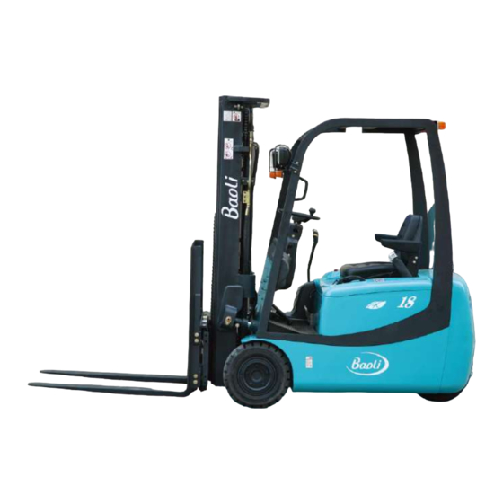
- Page 6 Ⅰ. External view and technical parameter External view of three-wheel electric forklift truck...
- Page 7 Technical parameter Model CPDS15 CPDS18 Rated capacity 1500 1750 Load center Power type Battery Tyre Super elastic solid tyre No. of tyre(front/rear) 2 / 2 Lift height 3000 3000 Free lift height 920×100×40 Fork size L×W×T α/β Mast tilt angle (forward/backward)
-
Page 8: Ⅱ . Safety Instruction, Operation & Maintenance Of Electric Forklift Truck
It is important for drivers and managers to remember the principle of “safety first” and ensure the safety operation as the description of Operation & Service Manual. Please read this manual thoroughly. This will give you a complete understanding of Baoli forklifts and permit you to operate them correctly and safely. -
Page 9: Storage Of Forklift Truck
Notice: Dismantling and slinging the component shall not be performed without the approval of our company. Under special circumstances, the appointed sling position should be used. The balance weight, fork and mast of the truck all have their appointed hang up position. The above – mentioned capacity is only for a reference, which may be adjusted because of configuration difference or technology optimization. - Page 10 (2) Wear the safety guards, such as clothing, shoes, helmet and gloves while operating the truck. (3) When the distance between the gravity center of loads and the fork arms is 500mm, the max. capacity is the rated capacity. When the distance exceeds 500mm, the capacity shall be based on the load chart.
- Page 11 (14) When loading and unloading goods, keep the mast vertical and the truck is in braking state. (15) Because the rear wheels steer your truck, the rear end swings wide when you turn. Use care in aisles and other tight places. (16) During operation, pay attention to the performance and condition of machinery, hydraulic, electric and speed adjuster.
- Page 12 (28) When travel with load, don’t tilt mast forward, don’t do handling. Don’t brake abruptly to prevent the bulk from slipping off the forks. (29) Drive the forklift truck to the stacked goods at a low speed, at the same time, pay much attention to sharp and hard objects which may prick the tyres.
-
Page 13: Periodic Servicing And Maintenance Of Electric Forklift Truck
Model value from the seat to the operator EN 12053 EN 13059 CPDS15-18 78.9dB(A) 0.87(m/s (44) Users select “Lengthening fork” in order to carry widening loads. Pay much attention not to overload and observe the allowable load and the capacity chart on the truck. - Page 14 During operating the forklift truck, it is necessary to operate carefully, service and maintenance periodically to make the forklift truck keep in good condition. 2.5.1 Handling a new forklift The performance and service life of forklift depends heavily upon the way you service it during the run-in period.
- Page 15 serviceman. Only trained and authorized serviceman shall be permitted to service the truck. Do not operate the truck until the truck has been repaired completely. (4) Maintain and service the motor, electric controller and battery separately according to their manuals. (5) Check all plugs once a month.
-
Page 16: Brief Operation Instruction
Adding oil, grease and brake fluid should follow relevant automobile standard. The waster of the forklift truck must be reclaimed obeying the relevant laws and regulations. Incorrect treatment will pollute water, soil and atmosphere etc. Wear safety guards such as helmet, safety shoes and working clothes to avoid directly contacting with body when adding oil, grease and brake fluid. - Page 17 Function and working condition of operation device: Name Function Working condition Parking brake Park the truck. Pull the lever backward fully. Control head Push or pull the double-shift Lamps switch combination lamp, switch when lighting. Adjust hand wheel’s headlamp, rear lamp. Adjust lever, hand wheel angle.
- Page 18 damaged or loosen. (2) Light switch: There are two switches on the left side of the meter. Press the right switch, the front combination lamp lights; press the left switch, the rear combination lamp lights. (3) Steering signal: Pull the steering lamp switch backward, the front lamp and rear up and down combination lamp turning signals on the left side of the truck light;...
-
Page 19: Caution Plates
history documents periodically. Never start the electric control of incorrectly-installing vehicles. Only trained people can do periodic maintenance and replace the damage parts with genuine parts of controller. Use the genuine parts produced by our company for ensuring the quality. During inspection, if there is status that may bring damage or cause dangerous, inform the agent immediately, they will make a decision of the operating security. - Page 20 (2) General information when operating (3) Nameplate of forklift truck (4) Lubrication system (5) Capacity chart...
- Page 21 (6) Inspections before starting (7) Add hydraulic oil (8) Sling decal (9) Sling point indication (10) Forbid entering into the rear space of the mast...
- Page 22 (11) Hand caution decal (12) Forbid conveying person (13) Routine battery use (14) Routine battery maintenance (15) Faulty starting decal (electric forklift truck witch DC motor) (16) Overturn caution decal...
-
Page 23: Ⅲ. Construction, Principle, Adjustment And Maintenance Of Forklift Truck
Ⅲ. Construction, principle, adjustment and maintenance of forklift trucks 1. Drive system 1.1 General description The drive system consists of general transmission system and partial brake system. With the front wheel duplex motor driving construction, the right and left front wheel separately contain drive axle, transmission case, brake unit and drive motor, which improves the working efficiency. - Page 24 Fig.1-1 Drive axle...
-
Page 25: Disassembly Of Drive System
1.1.2 Front wheel assy The front wheel is made up of rim and solid tyre. The types of the tyre and rim of the front wheel: Tyre size: 18×7-8 Outer diameter × Width = 457×170 (mm) Rim: 4.33R 1.2 Disassembly of drive system Before disassembling the transmission case, disassemble the front wheel assy and traction motor joint with it, then you can do maintenance and service on the parts of transmission case. -
Page 26: Assembly Of Drive System
The parts of transmission case should not be disassembled generally. If it’s necessary to disassemble it, please contact with the sale department of our company. 1.3 Assembly of drive system 1.3.1 Assembly of traction motor Before mounting, clean the mating surface between transmission case and traction motor with such as loctite 706 or alcohol carefully and make the surface dry, then check the surface for damage, if damaged, remove it with hone. - Page 27 When assembling the motor, for avoiding the happening of the noise in the future, don’t make the gear of motor hit the driving gear in the transmission case. 1.3.2 Mounting the transmission case on the frame (Fig.1-6) Check the surface of frame joint plate for damage and irregularities, and the regularity of transmission case surface is required not bigger than 0.1mm.
-
Page 28: Replenishing With Gear Oil
1.4 Replenishing with gear oil When the gear oil has been used for 1000 hours or one year (the accurate time is according to the first reached time), exhaust the gear oil in reduction box and replace with appointed gear oil, and do the detailed operation as follows: (a) Unscrew the drain plug (pos.1) with seal ring (pos.3), exhaust the gear oil, remove the iron powder on the drain plug, then retighten the drain plug, and... -
Page 29: Brake System
2. Brake system 2.1 General description The brake system consists of brake pedal, master cylinder and oil-lubricant brake. The oil-immersed multi-frictional plate brake is assembled in reduction box, eliminating the pollution, extending the life of brake unit and descending the maintenance cost. 2.1.1 Brake pedal The brake pedal assembly is of sling structure (see the construction as Fig.2-1), mounting on the meter bracket with bracket. - Page 30 2.1.2 Master cylinder The master cylinder contains valve support, check valve, return spring, primary cup, piston and secondary cup, which are all kept in place with stop washer and stop wire. The exterior of the cylinder is protected from dust by means of a rubber dust cover. The piston is actuated through the push rod by operation of the brake pedal.
- Page 31 2.1.3 Connecting the brake system and drive unit There are two connectors in the joint of drive unit and brake system, one used for connecting the traveling brake pipe while the other is used for the exhausting of traveling brake system. See it as Fig2-3. a) Connecting of traveling brake Connect the brake pipe connector and brake pipe with the torque 12-16Nm.
-
Page 32: Maintenance And Adjustment Of Brake System
2.1.6 Operation of brake system After assembling and debugging the traveling brake and parking brake, press the brake pedal, the normal traveling brake will be came out. Put the parking brake lever on the left side of meter bracket, the brake cable and the disk brake unit in the drive unit is engaged. - Page 33 comes into contact with the master cylinder piston. d) Tighten the push rod locking nut. 2.2.3 Adjust the brake switch (Fig.2-5) a) Loose the locking nut of the brake pedal after adjusting the height of brake pedal. b) Pull out the plug, separate the lead. c) Turn the switch, with the clearance A=1mm.
-
Page 34: Steering System
(See it as Fig3.1). The steering device is assembled on the rear of the frame, with the gear turning pushed by the steering motor, then the steering wheel can be turned to steering. Main parameter of steering system Model CPDS15 CPDS18 Item Model... - Page 35 Fig3.1 Steering system 3.1.1 Hand wheel Hand wheel is operated in normal way, that is to say, when turning the hand wheel right, the truck will turn right. When turning the hand wheel left, the truck will turn left. The rear wheels of the forklift truck are steering wheels, which make the back of the truck swing out when turning.
- Page 36 3.1.2 The principle of powered steering system with load sensing When turning the steering wheel, LS pipe will send the pressure signal from the throttle in the steering unit to the priority valve, with the pressure, the core of the check valve will be balanced to confirm the flow from CF port.
- Page 37 3.1.3 Steering device The steering device (Fig.3-3) consists of gear group, steering motor, steering axle body and steering wheel, etc. Driven by the gear motor hydraulic oil, the gear group makes the steering wheel turn, which drives steering axle body turning. The wheel is assembled in the rear wheel hub with wheel rim, while the rear wheel hub is assembled in the steering axle body with two tapered roller bearing.
-
Page 38: Adjustment And Maintenance
Fig.3-4 Steering motor 3.2 Adjustment and maintenance 3.2.1 Rear wheel bearing pre-load adjustment a) As shown in Fig3-5, fill up the chamber formed by wheel hubs, wheel hub bearings and wheel hub covers with lubrication grease. Coat the lips of the oil seals with lubrication grease. - Page 39 Fig.3-5 Pre-load adjustment 3.2.2 Inspection after reassembling the steering system a) Turn the steering wheel left and right, inspect whether the steering power is smooth. b) Inspect whether the connection of hydraulic pipeline is correct and whether the left and right steering is opposite. c) Lift up the rear wheels and slowly turn the steering wheel left and right several times to exhaust the air from the hydraulic pipeline and the steering cylinder.
-
Page 40: Electric System
4. Electric system 4.1 General description Electric system mainly consists of battery group, traction motor, lift motor, multifunctional integration controller system, control switch, liquid crystal instrument, harness and lighting device, etc. 1. Head lamp 2. Front combination lamp 3. Flash light 4. - Page 41 Fig.4-2 Principle of electric system...
-
Page 42: Sme Compact Meter
4.2 SME compact meter 4.2.1 General description Three-wheel AC electric forklift truck adopts Italy SME newly LCD meter, displaying in real-time on high definition LCD. The CAN wire of meter is connected with control main board according to RS232 communication standard. The EYE software obtains allowable landing and upgrade panel, with functions of detailed upgrade, diagnosis and adjustment. - Page 43 Traveling speed (Indicated from “0-9”) Overheated motor temperature warning Battery level (indicated by 9 segments) Display signals with alarm code 12 when battery is completely discharged. Charge the battery when indicating on 1 segment. Press E-S-H button, you can set operating mode for system. (E-economic mode, S-midrange mode, H-high mode) H-High mode: High acceleration, decelerate rate, max.
- Page 44 4.2.3 Troubleshooting of alarm code Alarm code Alarm description Alarm code Alarm description Max. battery voltage Min. battery voltage Pedal trimmer fault Eeprom alarm Pre-charge Power Inverter Capacitors Low battery voltage Over-heating motor Motor current offset alarm Main breaker Watchdog timer alarm Power inverter over-heating Alarm on 5V encoder voltage Alarm on 12V output voltage...
- Page 45 4.2.4 Process and instruction of meter (1) Turn on the key switch, some initial value mode will indicate for 3sec on the meter. The mode helping operators judge the type of the forklift truck will indicate on the position indicated speed, such as the four-wheel forklift truck is represented by CO. The information about speed, electric energy, turning angle, hand brake, seat switch, E/S/H selection and working hours is indicated on the meter, which help confirm the working state.
-
Page 46: Sme Ac Electric Control Assy
4.3 SME AC electric control assy 4.3.1 General description Three-wheel AC controller assy is composed of three power inverters which separately drives traveling and lifting motor, main control box, DC contactor, control aluminum sheet. Main control box is connected with power source module, separately controlling three power modules. -
Page 47: Distribution And Setting Of Sensor
4.4 Distribution and setting of sensor 4.4.1 General description The electric forklift truck embodies many superior features, such as infinitely variable lifting speed, steering speed adjuster and pedal setting, which can be adjusted and set in real-time by EYE software. These functions have been initialized before delivery and needn’t to be changed except the conditions as follows: 1. - Page 48 c) If electric potentiometer installs correctly, the output voltage value will be changed with hand wheel’s turning. d) Enter STEERING SENSOR CALIBRATION menu. e) Select ANTICLOCK parameter, turn hand wheel left until minimum steering value displays, save it. f) Enter CLOCK menu. g) Turn hand wheel right, until maximum steering value displays, save it.
-
Page 49: Ac Microtron
b) Connect PC machine with controller connector. c) Enter LIFT CALIBRICATION menu. d) Select MINIMUM parameter, the minimum value will be indicated in “lift calibration value” frame, save it. e) Enter MAXIMUM menu. f) Operate lift lever, until the maximum potentiometer output value indicates and save g) Enter MIDDLE menu. - Page 50 4.5.3 Setting for accelerator a) Install potentiometer on front backing plate, make sure the accelerator pedal on initial state. b) Connect PC machine with controller connector. c) If accelerator connects correctly, the output voltage will change with the stroke of the pedal.
-
Page 51: Sme Three-Phase Ac Motor
5. SME three-phase AC motor 5.1 General description The power system of three-wheel electric forklift truck is composed of two three-phase AC drive motors (6.5kw) and one three-phase AC lifting motor (12kw). It’s with function of speed sensor, temperature sensor, simple construction, reliable performance, free of maintenance. -
Page 52: Battery And Charger
6. Battery and charger 6.1 Structure of battery Battery is composed of lower pole plate, negative plate, clapboard, battery groove cap and electrolyte. Fig.6-1 Structure of battery 6.2 Specification of battery Model DA505 Capacity 505Ah/5h Voltage Density of electrolyte 1.280 g/cm Unit quantity Max. - Page 53 6.3.1 Information about battery operation (1) Before using the new battery, clean the surface and check for the damage. Smear butter or vaseline on the connectors to retard corrosion. (2) The battery is assembled on the truck for balance weight, if it’s lower than the min. weight, the load capacity will be affected.
- Page 54 water or deionizer water according to GB4554 standard. The density of electrolyte is 1.280-1.290g/cm (25℃). ▲Temperature conversion of density The density of electrolyte is changed with temperature, the relation is counted as follow formula: D25=D t+0.0007 D25—The density of electrolyte (g/cm ) at standard temperature (25℃) D t—The real density (g/cm ) when the temperature is t...
- Page 55 6.3.5 Adding distilled water (1) Get a certain amount of distilled water with a graduated container. (2) Open all pouring caps of battery units. (3) Absorb distilled water with ball type injector to charge the battery. When electrolyte is over 15-20mm upper the plate, stop charging. (4) After charging, tighten the pouring cap.
- Page 56 the discharged battery more than a day. If it is left idle for long time without charging, sulphatized pole plates will make the battery reduce performance. b. When the forklift truck is seldom used, it is necessary to charge the battery full before laying aside and then charge it once a month.
-
Page 57: Troubleshooting
6.3.8 Handle waste battery Waste battery should be handled properly in line with relevant laws and regulations. 6.4 Troubleshooting There are lots of reasons for the troubles, besides production quality or transportation and storage, unsuitable maintenance will lead to many troubles. After the failure launch, it’s necessary to analyze and take effective measures to remedy as soon as possible. - Page 58 Feature Cause Remedy 1. No gas or little during the Low charging current or Adjust charging current end stage of charging. charging not enough. and go on charging Short circuit of the inner 2. No gas after charging. Repair the short circuit battery.
- Page 59 6.5.1 Charger panel (1) When connect to power and turn switch, “Power” indication lamp lights. (2) When the battery quantity is full, “Full” indication lamp lights. (3) When the battery needs balanced charging, press “Balance” button and connect power, “-JH-”displays on the display screen , when pressing the button again, the charger restores to normal.
-
Page 60: Charger
(g) When the full indicator flashes, the battery capacity is full. The charger has entered automatically floating state, at the same time, the floating current of the charger is 1-3A. (h) After having charged, turn off the switch, disconnect the battery plug from the charger. -
Page 61: Hydraulic System
The hydraulic system consists of pump, control valve, lift cylinder, tilt cylinder and hydraulic pipes. The hydraulic oil, supplied by the oil pump connecting with the motor, is distributed to the oil cylinders by the control valve. Model CPDS15 CPDS18 Item Type Gear type... - Page 62 Fig.7-1 Outline of control valve (1) Spool valve operation (Take the tilt spool valve for example) (a) Neutral position (Fig7-2) The high-pressure oil from lift pump returns to the oil tank through the neutral position. Fig7-2 (b) Pushing-in of spool valve (Fig7-3) In this time, the spool is pushed in to close the mid-passage.
- Page 63 (c) Drawing-out of spool (Fig7-4) With the mid-passage closed, the oil from the main oil-inlet pushes up the check valve and flows into the port “A”. The return oil from the port “B” flows through the low-pressure passage to the tank. The spool can be restored to its neutral position by return spring.
- Page 64 As the imbalance pressure between the HP passage and the inside of oil pump, the pressure difference makes the valve “D” open, oil flows directly into the low pressure circuit “LP”. See Fig.7-8. Fig.7-8 (3) Action of tilt-lock valve Tilt spool valve housing contains a tilt-lock valve. The tilt lock valve is extended to prevent vibrations of the mast tilting from the negative pressure in the tilt cylinder and also to avoid the danger for mishandling of the tilt valve spool.
- Page 65 (4) Operation of the control valve The control valve is operated with the valve levers. All valve levers are assembled together with a shaft and the shaft is assembled on the front guard with the bracket. The valve levers operate the control valve with the joints. See Fig. 7-11. Fig.
- Page 66 As you see in Fig.7-12, the mast lift up when you push the lift lever forward, the mast fall down when you pull the lift lever backward. The mast tilt forward when you push the tilt lever forward, the mast tilt backward when you pull the tilt lever backward. (5) Setting pressure of the relief valve The pressure of the relief valve has been set before delivery.
- Page 67 7.1.3 Lift cylinder The lift cylinder is of single-action piston type. It consists of primarily of cylinder body, piston rod, piston and cylinder head. The bottom of the cylinder is connected with the cylinder supporter of the outer mast by blots and pins, while its top (i.e. piston rod head) is connected with the upper beam of the outer mast.
- Page 68 At the bottom of the lift cylinder is a cut-off valve (see Fig.7-15), which operates when the high-pressure hose bursts for any reason to prevent the load from dropping down abruptly. The oil from the lift cylinder flows through small holes in the circumference of the cut-off valve spool and produces a pressure difference between two chambers.
- Page 69 7.1.4 Flow regulator valve The flow regulator valve, located in the lift cylinder circuit to limit the descending speed of loaded forks, has the construction as shown in Fig.7-16. When the lift spool is placed in the “lift” position, the oil from the control valve flows through the oil chambers A and B, oil holes C, D, E and F, and the chamber G to the lift cylinder without any regulation.
- Page 70 7.1.5 Tilt cylinder (Fig.7-17) The tilt cylinder is of double-acting type. Each truck has two tilt cylinders which are installed on two sides of the mast assembly with pin while their piston rod ends are connected with the outer mast channels. The tilt cylinder assembly consists primarily of piston, piston rod, cylinder body, cylinder base, guide sleeve and seals.
- Page 71 7.1.6 Oil tank For the cleaning oil, there is an inlet filter and a return filter separately in the oil tank and the tube. 7.1.7 Hydraulic oil circuit (See Fig.7-18) Fig.7-18 Hydraulic oil circuit Forklift truck 1.5t 1.8t Main relief pressure 14.5MPa 16MPa Steering unit pressure...
-
Page 72: Maintenance And Adjustment Of Hydraulic System
7.2 Maintenance and adjustment of hydraulic system 7.2.1 Maintenance of gear pump 1. Pump body 2. Drive gear 3. Driven gear 4. Front cover 5. Rear cover 6. Lining plate 7. Seal ring 8. Snap ring 9. Oil seal 10. Snap ring 11. - Page 73 2. Inspection The disassembled parts except rubber parts should be washed with gasoline. (a) Pump body inspection (Fig.7-20) If the scraping trace is up to 1/2 long of the inner periphery, it indicates that the bearing and gear shaft are subject to excessive wear, replace the pump body. (b) Lining plate inspection (Fig.7-21) Inspect the contact surface of the lining plate.
- Page 74 3. Assembly (a) Install a new seal ring and a new ring on the front cover of pump. (b) Install the lining plate on the groove of the front cover, don’t confuse the inlet oil port and the outlet oil port. (c) Install the driving gear and the driven gear on the front cover.
- Page 75 (d) Without the change of the speed in step, increase the pressure to 20 to 30 kg/cm at a time and run the pump for five minutes. Then increase the pressure to 175 kg/cm Each circuit works for five minutes and then renews the return filter. During the increase of the pressure, observe the change of oil temperature and pump body surface temperature and working voice.
- Page 76 2. Gear pump Problem Possible cause Remedy Lower oil level of oil tank Add oil up to specified level Less exhausting oil Blocked pipe-line or oil filter Clean or replace oil Lining plate, seal ring, bushing Replace seals or snap ring broken down Adjust the pressure of surplus Lower pressure of Misadjusted surplus valve...
-
Page 77: Mast System
8. Mast system 8.1 General description The mast system is the type of lifting and descending vertically with rollers of the two-stage. It consists of inner mast, outer mast and lift bracket. The fork is fastened on the bracket upper beam groove with pin, the fork clearance can be adjusted. - Page 78 Fig.8-1 Inner and outer mast 1. Outer mast 7. Bolt 13. Adjust gasket 19. Snap ring 2. Pin 8. Bolt 14. Guide plate 20. Chain assy 3. Grease 9. Washer 15. Roller bearing 21. Short bolt 4. Mast bearing 10. Side roller bearing 16.
- Page 79 8.1.2 Carriage The carriage moves up and down smoothly along the channel of the inner mast with main rollers. The main rollers are mounted on the main roller shafts and blocked by snap rings. The main roller shafts are welded on the carriage. The side rollers fitted on the carriage with bolts.
-
Page 80: Maintenance And Adjustment Of Mast System
Fig.8-3 Roller position 8.2 Maintenance and adjustment of mast system 8.2.1 Adjustment of lift cylinder When replace the lift cylinder, inner mast or outer mast, we shall readjust the stroke of the lift cylinder as following. (1) Install the piston rod in the upper beam of the inner mast without shims. (2) Lift the mast slowly to the max. - Page 81 8.2.2 Carriage adjustment (1) Let the truck parking on the horizontal ground and make the mast vertical. See it as Fig.8-5. (2) Let the bottom of the fork contact with the ground. Adjust the adjusting nut for the end nipple of the upper chain and make a distance A between the main roller and the carriage.
- Page 82 8.2.4 Mast rollers replace (1) Use the same way as 8.2.3 to disassemble the carriage from the inner mast. (2) Let the truck parking on the horizontal ground and wedge up the front wheels for 250 to 300mm. (3) Apply the parking brake and wedge up the rear wheels. (4) Disassemble the fitted bolts for the lift cylinder and the inner mast.
-
Page 83: Charging Record Card Of Electric Forklift Truck
Appendix: Charging record card of electric forklift truck Model of truck: Identification No: Date of purchasing: Model of battery: Battery No: Date of first using: Density of Fluid level of Charging Charged electrolyte (g/cm Voltage Distilled Date electrolyte hours electricity (before charge water (ml) (Normal / lower) - Page 84 NOTE _______________________________________________________________________ _______________________________________________________________________ _______________________________________________________________________ _______________________________________________________________________ _______________________________________________________________________ _______________________________________________________________________ _______________________________________________________________________ _______________________________________________________________________ _______________________________________________________________________ _______________________________________________________________________ _______________________________________________________________________ _______________________________________________________________________ _______________________________________________________________________ _______________________________________________________________________ _______________________________________________________________________ _______________________________________________________________________ _______________________________________________________________________ _______________________________________________________________________ _______________________________________________________________________ _______________________________________________________________________ _______________________________________________________________________ _______________________________________________________________________...
-
Page 85: Ec Declaration Of Conformity
EC DECLARATION OF CONFORMITY MANUFACTURE KION Baoli(Jiangsu) Forklift CO., LTD. Name: No.8 Xinzhou Road, Economic Development Zone, Address: Jingjiang ,Jiangsu, China ,Jiangsu, China Post: 214500 THE TECHNICAL DOCUMENTATION WAS COMPILED BY: Wu,Yun-Cheng Name: Hoppengarten 19,Germany Address: 40489 Duesseldorf,Germany Post: HEREBY DECLARES THAT THE PRODUCT DESCRIBED BELOW: Industrial truck –... - Page 86 KION Baoli (Jiangsu) Forklift Co., Ltd. Service Hotline: 400-828-2789 Tel: +86 523 8461 6148 Fax: +86 523 8461 6126 P.C.: 214500 Add: No. 8 Xinzhou Road·Economic Development Zone·Jingjiang·Jiangsu·China www.baoli-mh.com * We reserve the right to make any changes or modifications of pictures and specifications in this manual without giving previous notice and without incurring any obligation.
Need help?
Do you have a question about the CPDS15 and is the answer not in the manual?
Questions and answers