Table of Contents
Advertisement
Advertisement
Table of Contents

Related Manuals for Baoli CPD10


Summary of Contents for Baoli CPD10
- Page 2 C P D 1 0 - 3 0 DC CPD10J-30J AC Balanceweight Type Electric Forklift Truck 1-3T OPERATION & SERVICE MANUAL KION Baoli (Jiangsu) Forklift Co., Ltd.
- Page 3 PREFACE Balance weight type electric forklift trucks are designed on the base of the advanced features available from both local and foreign designs. These trucks are suitable to handle, transport and stack goods in factories, mines, stations, ports, freight yards, warehouses and used widely in food processing, textiles and other light industries.
-
Page 4: Table Of Contents
CONTENTS Ⅰ. External view and specification ………………………………………………………… 1 Ⅱ. Safety instruction, operation & maintenance of electric forklift truck …………… 8 2.1 Shipping, loading, unloading and slinging of electric forklift truck ………………… 8 2.2 Storage of forklift truck ……………………………………………………………………… 9 2.3 Precautions before operation ……………………………………………………………… 9 2.4 Information of safety operation ……………………………………………………………... - Page 5 4.8 Harness ……………………………………………………………………………………… 72 5. Motor ……………………………………………………………………………………… 75 5.1 General description of DC motor ………………………………………………………… 75 5.2 SME three-phase AC motor ……………………………………………………………… 77 5.3 Inspection and maintenance of DC motor ……………………………………………… 78 5.4 Failure diagnosis of DC motor ………………………………………………… 8 4 6.
-
Page 6: Ⅰ. External View And Specification
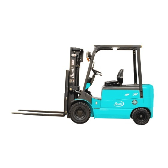
Ⅰ . External view and specification External view of electric forklift truck... - Page 7 SPECIFICATION (CPD10 CPD15) Model CPD10 CPD15 Power type Battery 蓄电池 Rated capacity 1000 1500 Load center Lift height 3000 Free lift height 3000 L×W 920×100×40 Fork size ×T 920×120×40 Fork outside spread (Min./Max) 200/968 Mast tilt angle 200/980 6/12 α/β...
- Page 8 SPECIFICATION (CPD10J CPD15J) Model CPD15J Power type Battery 蓄电池 Rated capacity 1500 Load center Lift height 3000 Free lift height 3000 L×W×T 920×100×40 Fork size Fork outside spread (Min./Max) 200/968 α/β ° Mast tilt angle (forward/backward) 6/12 Front overhang Length to fork face 2056 Overall width 1090...
-
Page 9: Failure Diagnosis Of Dc Motor
SPECIFICATION (CPD20 CPD25) Model CPD20 CPD25 Power type Battery 蓄电池 Rated capacity 2000 2500 Load center Lift height 3000 Free lift height L×W×T 1070×120×40 Fork size 1070×120×45 Fork outside spread (Min./Max) 240/1040 α/β ° Mast tilt angle (forward/backward) 6/12 Front overhang Length to fork face 2349 2381... - Page 10 SPECIFICATION (CPD20J CPD25J) Model CPD20J CPD25J Power type Battery 蓄电池 Rated capacity 2000 2500 Load center Lift height 3000 Free lift height L×W×T 1070×120×40 Fork size 1070×120×45 Fork outside spread (Min./Max) 240/1040 α/β ° Mast tilt angle (forward/backward) 6/10 Front overhang Length to fork face 2349 2381...
- Page 11 SPECIFICATION (CPD30) Manufacturer KION Baoli Model CPD30 Power type Battery 蓄电池 Rated capacity 3000 Load center Lift height 3000 Free lift height 3000 L×W×T 1070×125×45 Fork size Fork outside spread (Min./Max) 250/1100 α/β ° Mast tilt angle (forward/backward) 6/10 Front overhang...
- Page 12 SPECIFICATION (CPD30J) Model CPD30J Power type Battery 蓄电池 Rated capacity 3000 Load center Lift height 3000 Free lift height 3000 L×W×T 1070×125×45 Fork size Fork outside spread (Min./Max) 250/1100 α/β ° Mast tilt angle (forward/backward) 6/10 Front overhang Length to fork face 2481 Overall width 1265...
-
Page 13: Ⅱ. Safety Instruction, Operation & Maintenance Of Electric Forklift Truck
It is important for drivers and managers to remember the principle of “first safety” and ensure the safety operation as the description of Operation & Service Manual. Please read this manual thoroughly. This will give you a complete understanding of Baoli forklifts and permit you to operate them correctly and safely. -
Page 14: Storage Of Forklift Truck
Notice: Dismantling and slinging the component shall not be performed without the approval of our company. Under special circumstances, the appointed sling position should be used. The balance weight, fork and mast of the truck all have their appointed hang up position. The above – mentioned weight is only for a reference, which may be adjusted because of configuration difference or technology optimization. - Page 15 (3) When the distance between the gravity center of loads and the fork arms is 500mm, the max. capacity is the rated capacity. When the distance exceeds 500mm, the capacity shall be based on the load chart. Handle only loads within the allowable capacity of the truck.
- Page 16 (14) When loading and unloading goods, keep the mast vertical and the truck is in braking state. (15) Because the rear wheels steer your truck, the rear end swings wide when you turn. Use care in aisles and other tight places. (16) During operation, pay attention to the performance and condition of machinery, hydraulic, electric and speed adjuster.
- Page 17 (27) Be careful and slowly driving over a dock board or bridge-plate. (28) When travel with load, don’t tilt mast forward, don’t do handling. Don’t brake abruptly to prevent the bulk from slipping off the forks. (29) Drive the forklift truck to the stacked goods at a low speed, at the same time, pay much attention to sharp and hard objects near the goods, otherwise, the tyres will be pricked.
-
Page 18: Periodic Servicing And Maintenance Of Electric Forklift Truck
The noise pressure level at The vertical direction acceleration mean the operator’s position Model value from the seat to the operator EN 12053 EN 13059 CPD10-15 69.1dB(A) 1.10(m/s CPD20-25 78.3dB(A) 1.08(m/s CPD30 63.9dB(A) 1.11(m/s... - Page 19 2.5 Periodic servicing and maintenance of electric forklift truck During operating the forklift truck, it is necessary to operate carefully, service and maintenance periodically to make the forklift truck keep in good condition. 2.5.1 Handling a new forklift The performance and service life of forklift depends heavily upon the way you handle it during the break-in period.
- Page 20 Refer to Manual of Battery about charging method and maintenance. 2.5.4 Essentials of servicing (1) Some critical components must be replaced according to demands periodically. Use genuine parts only. (2) Use genuine or recommended oil only when replacing or adding. (3) If any damage or fault is found, the matter should be reported to the manager.
-
Page 21: Brief Operation Instruction
Notice: When serving and checking the truck, do not use the mast or the load backrest instead of a ladder, these actions will lead to a dangerous condition unexpectedly. 2.5.5 Recommended oil and grease Brand or code Amount Remark Name Domestic Overseas 1-1.5T 2-2.5T... - Page 22 Function and working condition of operation device and meter: Name Function Working condition Parking brake Park the truck. Pull the lever backward fully. Adjust hand wheel’s Adjust lever, hand wheel angle. Foot brake pedal Brake the truck. Depress the pedal to brake. Change traveling Pull the lever forward, the truck Shift lever...
- Page 23 (2) Lamp switch: Pull shiftⅠ , front and rear clearance lamps light. Pull shiftⅡ , the head lamps light while the clearance lamps light too. (3) Steering signal: Pull the steering lamp switch backward, the front and rear combination turning signals on the left side of the truck light; pull the turning lamp switch forward, the front and rear combination turning signals on the right side light.
- Page 24 combination turning signals on the left side of the truck light; pull the steering lamp switch forward, the front and rear combination turning signals on the right light. (4) Brake signal: When braking, press down the brake pedal to turn on the rear combination brake lamps (red).
-
Page 25: Caution Plates
genuine parts of controller. Use the genuine parts produced by our company for ensuring the quality. During inspection, if there is status that may bring damage or cause dangerous, inform the agent immediately, they will make a decision of the operating security. 2.6.5 Particular notice (1) As a special vehicle, electric forklift trucks need professional maintenance and authorized persons’... - Page 26 (2) General information when operating (3) Nameplate of forklift truck (4) Lubrication system...
- Page 27 (5) Capacity chart (6) Inspections before starting (7) Adjust parking brake (8) Add hydraulic oil...
- Page 28 (9) Tyre safety decal (charging tyre) (10) Sling decal (11) Sling point indication (12) Forbid entering into the rear space of the mast...
- Page 29 (13) Tyre pressure decal (charging tyre) (14) Hand caution decal (15) Forbid conveying person (16) Routine battery use...
- Page 30 (17) Routine battery maintenance (18) Faulty starting decal (electric forklift truck witch DC motor) (19) Overturn caution decal...
-
Page 31: Ⅲ. Construction, Principle, Adjustment & Maintenance Of Electric Forklift Truck
Ⅲ . Construction, principle, adjustment and maintenance of electric forklift truck 1. Transmission system 1.1 General description The transmission system consists of a gear box assembly, differential assembly and drive axle. With direct connection of the drive gear and the drive motor, the travel speed of the truck can be changed with rotating speed of the motor, and the travel direction can be changed with the rotation direction of the motor. - Page 32 Fig.1-1 Gear box and differential (1-1.5t) 1.Ring gear 2.Planet gear 3.Gear shaft 4.Differential housing 5.O-ring 6.Cover 7.Bearing 8.Reducer housing 9.Bearing 10.Bearing seat 11.Bearing 12.Nut 13.Adjust shim 14.Adjust shim 15.Oil seal 16.Drivel gear & shaft 17.Shim 18.Gear shaft 19.Bevel gear 20.Bearing 21.Bearing seat 22.Lock washer...
- Page 33 Fig.1-2 Gear box and differential (2-3t)
- Page 34 Fig.1-3 Differential...
- Page 35 1. Housing 2. Half-shaft 3. Wheel brake 4. Brake drum 5. Oil seal 6. Taper bearing 7. Wheel hub 8. Taper bearing 9. Oil seal 10. Tyre 11. Rim 12. Hub nut 13. Lock nut Fig.1-4 Drive axle...
-
Page 36: Assembly Of Wheel Hub
1.2 Assembly of wheel hub (1) Fill the chamber of wheel hub with lithium base grease about 100 cc, then fit the hub on the shaft. (2) Screw down the adjusting nut with a torque for about 1kg.m and then loosen it for 1/2 turn. -
Page 37: Brake System
2. Brake system 2.1 General description The brake system is the front two-wheel braking interior extended hydraulic type consisting of a master cylinder, wheel brakes and brake pedal. 2.1.1 Brake pedal The structure of the brake pedal which is assembled on meter rack with bracket is indicated in Fig.2-1. - Page 38 back to the reserve tank through the return port until primary cup blocks up the return port. After the primary cup passes through the return port, the brake fluid in the cylinder is pressurized and opens the check valve, flowing through the brake pipeline to the operating cylinder.
- Page 39 (1) The operation of wheel brake is as follows: The primary and secondary shoes are respectively forced by a force equaled in value and contrary in direction, by operation of the operating cylinder to bring that the friction piece being in contact with the brake drum. The primary shoe forces the adjuster with the aid of friction force between the friction piece and the drum.
- Page 40 Fig.2-5 Parking brake device Fig.2-6 Clearance self-adjuster ▲Motion of clearance self-adjuster When the brake pedal is pressed in reverse travel, the brake shoes are expanded, as a result, the primary and secondary shoes come into contact with the brake drum and rotate together.
- Page 41 Fig.2-8 Wheel brake (1-1.5t) 1 Parking pull rod 8 Pressure spring 15 Dust ring 2 Primary brake shoe 9 Secondary brake shoe 16 Cylinder body 3 E-retainer 10 Spring 17 Piston 4 Operating cylinder 11 Ratchet pawl 18 Spring 5 Return spring 12 Clearance self-adjuster 19 Cup 6 Parking push rod...
- Page 42 Fig.2-9 Wheel brake (2-3t) 1 Operating cylinder 6 Parking push rod 11 Spring 2 Spring 7 Pressure spring 12 Parking pull rod 3 Push rod 8 Spring 13 Primary brake shoe 4 Secondary brake shoe 9 Ratchet pawl 14 Return spring 5 Backing plate 10 Clearance self-adjuster...
- Page 43 2.1.4 Parking brake control device The parking brake lever is of a cam type. The brake force can be adjusted with the adjuster on the end of the brake lever. Brake force adjustment: When you turn the adjuster clockwise, the force increases, otherwise, when you turn the adjuster counterclockwise, the force decreases.
-
Page 44: Disassembly, Assembly And Adjustment Of Wheel Brake
2.2 Disassembly, assembly and adjustment of wheel brake This paragraph covers the disassembly, assembly and adjustment of the wheel brake, the adjusting method of brake pedal, when the wheel and wheel hub is disassembled. The description here is mainly for the brake of 3t forklift truck, the other forklift trucks are similar in maintenance in general except the structure of adjuster. - Page 45 assembly out of the operating cylinder. See Fig.2-18. Fig.2-15 Fig.2-16 Fig.2-17 Fig.2-18 2.2.2 Inspection of wheel brake Inspect all parts to make sure if there’s any worn or damaged part. If necessary, repair or replace with new one. (1) Check the inner surface of operating cylinder and the periphery surface of the piston for rusting.
- Page 46 Unit: mm 1.0-1.5 2.0t-2. Specified thickness Min. thickness (5) Check the condition of the brake drum’s inner surface. If any damage or excessive wear is found, repair by machining or replace it. See Fig. 2-21. Unit: mm 1.0-1.5t 2.0t-2.5t Specified thickness Max.
- Page 47 Fig. 2-23 Fig. 2-24 (9) Install the adjuster, adjuster spring, push rod and its return spring. Pay attention to the following points: (a) Thread direction of the adjuster and its mounting direction. (b) Adjuster spring direction (Do not allow the adjuster gear teeth to contact with the spring).
- Page 48 Fig. 2-27 (2) If the adjuster fails to do the above operation when the adjusting lever is pulled, proceed with the following inspection: a) Make sure that the adjusting lever, push rod, rod spring and the return spring for push rod are securely installed.
- Page 49 ▲ Brake switch adjustment (1) After you adjust the height of the brake pedal, loose the lock nut of the brake switch. (2) Pull the plug out to let the lead separate. (3) Turn the switch to make the clearance about 1mm. (4) When you press the brake pedal make sure that the brake lamps light at the same time.
-
Page 50: Steering System
3. Steering system 3.1 General description The steering system consists of steering hand-wheel, steering shaft, steering oil pump, and steering axle. The steering shaft is connected with steering unit by knuckle, which connects the connection shaft and hand-wheel. The steering column can be tilt forward and backward to suitable position (see Fig. - Page 51 3.1.2 Powered steering unit (Fig. 3-2) The powered steering unit can transmit the pressure oil from the flow-divider by metering to the steering cylinder in terms of the rotating angle of the hand-wheel. When the steering pump stops running, a manpowered steering should be adopted. The powered steering unit consists of a general steering unit and a combination valve.
- Page 52 3.1.3 Steering axle The steering axle is of section-boxed welded construction type (Fig.3-3). It includes axle body, steering cylinder, link lever, steering knuckle and steering wheel. The steering axle is of slider crank mechanism. The cylinder piston rod pushes knuckle steering through link lever, causing wheel’s deflection and truck’s steering.
- Page 53 (1) Steering knuckle Both steering knuckles are fitted between the upper and the lower axle body through two king pins, tapered bearing, dust cover and O-ring. The king pin is locked on the steering axle body with upper being with backing pin and lower being with cotter pin. Both ends of the king pin are supported by tapered bearing which are pressed into the axle body.
-
Page 54: Adjustment And Maintenance
(3) Wheel hub The rear wheel hubs are fitted to the knuckle shafts through two tapered roller bearings, the wheels with rims are bolted on the hubs. There are oil seals keeping the grease in the hubs and the chambers of the knuckles between the inside of the two tapered roller bearings. - Page 55 3.2.2 Inspection after reassembling the steering system (1) Turning the steering hand-wheel right and left to the bottom, inspect whether strength of left and right steering is uniform, the steering power is smooth. (2) Inspect whether connection of the hydraulic pipeline and left and right steering is correct.
-
Page 56: Electric System
4. Electric system 4.1 General description The electric system is composed of battery, drive motor, lift motor, multifunctional controller system, control switch, LCD combined instrument and lamps etc. The construction and principle of electric system is referred to: Electric forklift truck with DC motor (Fig.4-1, Fig.4-2, Fig.4-3). Electric forklift truck with AC motor (Fig.4-4, Fig.4-5). - Page 57 Fig.4-2 Principle of electric system (DC CPD10-25)
- Page 58 Fig.4-3 Principle of electric system (DC CPD30)
- Page 59 1. Head lamp 2. Front combination lamp 3. Inching switch 4. Lift potentiometer 5. Meter assy 6. Steering switch 7. Direction switch 8. Hand brake 9. Horn 10. Horn absorber 11. Foot horn switch 12. DC convertor 13. Microrelay 14. Back-up buzzer 15.
- Page 60 Fig.4-5 Principle of electric system (AC)
-
Page 61: Multifunctional Integration Control System (Dc)
(2) The accelerator is composed of start switch and potentiometer. The potentiometer converts the degree of the pedal into changes in the resistance of the potentiometer, then transfer to the controller by means of voltage change. (Fig.4-8) Fig.4-6 Controller assy(DC CPD10-25) - Page 62 Fig.4-7 Controller assy (DC CPD30) Red (Start switch) Orange (Start switch) Blue (Potentiometer) Brown (Potentiometer) Fig.4-8 Accelerator...
-
Page 63: Sme Ac Electric Controller Assy
4.3 SME AC electric controller assy (1) General description Four-wheel AC controller assy is composed of two power inverters which separately drives traveling and lifting motor, main control box, DC contactor, control aluminum sheet. Main control box is connected with power source module, separately controlling two power modules. - Page 64 4.4.2 Steering potentiometer 1. Specification of steering potentiometer Resistance limitation: 0KΩ-5KΩ Steering angle: 0°-360° Voltage: 12V 2. Adjustment a) Install the potentiometer on truck body, make steering wheels on zero degree(straight traveling direction), adjust potentiometer to make output resistance value be about 2.5 KΩ, if there is deviation, the output resistance must be between 0 KΩ...
- Page 65 Do trial operation, check if the position of steering wheel and displaying angle of meter is consistent (range over 0 , 90 , -90 4.4.3 Lifting potentiometer 1. Specification Resistance limitation: 0KΩ-5KΩ Effective straight travel: 9±0.5mm Voltage: 12V 2. Adjustment a) Install potentiometer on the first level lift of multi-way valve, make sure that the top lever of potentiometer runs freely.
-
Page 66: Ac Microtron
h) Operate lift lever, until indicating middle value between minimum value and maximum value, save it. i) Quit the menu. 4.5 AC microtron 1. Outline and port function 2. Sketch for connector and port Definition Color Switch output1 Yellow Switch output2 Blue Power positive input (12V+) Power negative input (12V-) -
Page 67: Led Instrument (Dc)
e) Press the pedal slowly until START lamp lights, save it. f) Select MINIMUM menu, press the pedal slowly until output value is larger than start value, save it. g) Select MAXIMUM menu, press the pedal slowly until the max output value occurs, save h) Get out of menu. - Page 68 (1) Voltmeter It indicates voltage of the battery. The single cell voltage must greater than 1.80V, that is to say, when the forklift truck with load, the voltage of 48V battery can’t be lower than 43.2V, the voltage of 80V battery can’t be lower than 72V. (2) Lamp switch &...
- Page 69 4.6.3 Meter connector Color Port No. Function Input power 12V Dual switch shift Ⅰ (width indication) Purple Dual switch shiftⅡ (head lamp) Orange Hand brake signal(48V) Blue Forward signal Brown Backward signal Gray Input left turning signal Yellow Input right turning signal Green Input short signal Pink...
- Page 70 4.6.4 Troubleshooting instructions If misoperation of the vehicle or trouble of electronic control occurs, a state code will be displayed on the instrument. With the status code number, follow the procedures outlined in the status code instruction sheets to determine the problem. Status code Description of status STATECOD...
-
Page 71: Sme Compact Meter (Ac)
4.7 SME compact meter (AC) 4.7.1 General description Four-wheel AC electric forklift truck adopts Italy SME newly LCD meter, displaying in real-time on high definition LCD. The CAN wire of meter is connected with control main board according to RS232 communication standard. The EYE software obtains allowable landing and upgrade panel, with functions of detailed upgrade, diagnosis and adjustment. - Page 72 SME meter connector Illustration for SME meter connector Display type Specification Operating voltage +12V Supply current 150A MAX. Operating temperature -30℃~+50℃ Protection IP54 Connections lin-bus Input1 Input2 Input3 Input4 Lin-bus 19.2 KBIT/S +12V...
- Page 73 4.7.3 Outline and instructions of meter Compact meter engineered by SME Traveling speed (km/h) Hand brake switch, lamp lights when pulling the hand brake With safety seat switch open, meter indicates seat symbol, main contactor can’t be connected and truck can’t travel until seat switch closes.
- Page 74 Battery level (indicated by 9 segments) Display signals with alarm code 12 when battery is completely discharged. Charge the battery when indicating on 1 segment. Press E-S-H button, you can set operating mode for system. (E-economic mode, S-midrange mode, H-high mode) H-High mode: High acceleration, decelerate rate, max.
- Page 75 Process and 4.7.4 instruction of meter (1) Turn on the key switch, some initial value mode will indicate for 3sec on the meter. The mode helping operators judge the type of the forklift truck will indicate on the position indicated speed, such as the four-wheel forklift truck is represented by CO. The information about speed, electric energy, turning angle, hand brake, seat switch, E/S/H selection and working hours is indicated on the meter, which help confirm the working state.
- Page 76 4.7.7 Troubleshooting of AC electric forklift truck Alarm code Alarm code Alarm description Alarm description Maximum battery voltage Minimum battery voltage Pedal trimmer fault Eeprom alarm Pre-charge Power inverter Inverter Capacitors Low battery voltage Over-temperature motor Motor current offset alarm Main breaker Power inverter Watchdog timer alarm...
-
Page 77: Harness
4.8 Harness Fig.4-10 Harness (DC CPD10-30) - Page 78 Fig. 4-11 Harness (AC CPD10J-15J)
- Page 79 Fig. 4-12 Harness (AC CPD20J-30J)
-
Page 80: Motor
5. Motor 5.1 DC motor 5.1.1 Main parameter Type 1-1.5t forklift truck 2-2.5t forklift truck 3t forklift truck Item Drive motor Name XQ-5-3A1 XQ-7A3 XQ-10.2A Excitation Separately Separately Separately Rated power 5.3kw (an hour) 7kw (an hour) 10.2kw (an hour) Rated voltage Rated current 139A... - Page 81 Fig 5-1 Assembly diagram of lifting motor Fig5-2 Lifting motor...
-
Page 82: Sme Three-Phase Ac Motor
5.2 SME three-phase AC motor The power system of four-wheel electric forklift truck is composed of three-phase AC drive motor and three-phase AC lifting motor. It’s with function of speed sensor, temperature sensor, simple construction, reliable performance, free of maintenance. (Fig.5-3) Fig.5-3 Structure of AC motor 1. -
Page 83: Inspection And Maintenance Of Dc Motor
5.3 Inspection and maintenance of DC motor 5.3.1 Maintenance and service when driving Item Part Judgment Remedy Clean the dust Dust Visualization: Compare with the normal Motor Foreign Environment Return to driving conditions and judge if frame matter, normal. the temperature is normal. liquid Compare with normal Motor... - Page 84 5.3.3 Periodic inspection of motor 1. Inspecting judgment Inspection frequency of the motor is related with operation time every day. But at thick dust or high humidity place, it is necessary to add inspection frequency. Operation time More than 12 hours everyday Less than 12 hours everyday Check frequency Once every year...
- Page 85 2. Inspecting essential During periodic inspections, please abide by the following essentials. (1) Select a clean and dry place. (2) When disassembling, taking notes of the order of disassembled parts is necessary. Put the screws and washers into a prepared empty box. (3) When disassembling or assembling parts such as bracket, strike at it slightly with a wood hammer.
- Page 86 (2) Check the terminals and outlets for correctness and tightness. (3) The electric brush must slide smoothly in brush box. (4) Check if commutator pieces are clean, if necessary, clean the carbon powder on gaps between commutator pieces and on the commutator surface with soft down less cloth.
- Page 87 Fig. 5-4 Method of polishing 5. Inspection and maintenance of bearing (1) Inspection and maintenance The service life of the bearing varies with the load and driving condition. If the bearing was observed high temperature or abnormal noise, replace it immediately. Sealed bearing is of effective lubrication because it is sealed high quality lithium grease, its structure also can prevent the dust from entering, with no need of replenishing butter for long time.
- Page 88 ▲Assemble bearing Assemble bearing with steel pipe or retainer. The temperature can’t be out of 60℃-80℃ when loosening the motor bearing. Fig.5-6 Assemble bearing 6. Measure insulating resistance Connect negative pole of the meter with motor bedplate, positive pole with either of the two terminals, the measured value should be more than 0.5 MΩ.
- Page 89 5.4 Failure diagnosis of DC motor Failure Reason All copper pieces are ·The pressure of electric brush is incorrect. black ·Commutator pieces are short circuit. The commutator pieces ·Armature coil is short circuit. are black with the regular ·The commutator pieces and armature coil are faulty order.
-
Page 90: Battery And Charger
6. Battery and charger 6.1 Structure of battery The battery is composed of lower-pole plate, negative plate, clapboard, capping and electrolyte. 6.2 Specification of battery and charger Type 1-1.5t 2-2.5t forklift truck forklift truck forklift truck Item Capacity 440AH/5h 700AH/5h 500AH/5h Name D-440BS... -
Page 91: Usage And Maintenance Of Battery
6.3 Usage and maintenance of battery The correct using and daily maintenance is very important for the performance and useful life of lead-acid battery. Operators must maintain and service the battery according to the manual and realities, fill in the record card of charging. The card can be copied as the daily inspection record, referred to the attached list at the back of the manual. - Page 92 battery is not often used, a balanced charging (an amount over charge) every month is necessary. 6.3.2 Compound electrolyte (1) The electrolyte of battery must be compounded with sulphuric acid and distilled water or deionizer water according to GB4554 standard. The density of electrolyte is 1.280-1.290g/cm (25℃) ▲Temperature conversion of density...
- Page 93 density of electrolyte, put the sucker of the densimeter into the electrolyte vertically, extruding the rubber tube with finger, then the electrolyte will be absorbed into the glass tube, at last, the buoy of densimeter will float. Read the number of densimeter. Note: The densimeter must be floated vertically, not lean to the glass tube.
- Page 94 6.3.6 Charge the battery (1) Precaution when charging (a) Each time after the battery is discharged, it should be charged in time. Don’t place the discharged battery more than a day. If it is left idle for long time without charging, sulphatized pole plates will make the battery reduce performance.
-
Page 95: Troubleshooting Guide
6.3.8 Handle waste battery Waste battery should be handled properly in line with relevant laws and regulations. 6.4 Troubleshooting guide There are lots of reasons for the troubles, besides production quality or transportation and storage, unsuitable maintenance will lead to many troubles. After the failure launch, it’s necessary to analyze and take effective measures to remedy as soon as possible. -
Page 96: Charger
Feature Cause Remedy 1. No gas or little Low charging Adjust charging current during the end stage current or charging and go on charging of charging. not enough. 2. No gas after Short circuit of the Repair the short circuit charging. - Page 97 6.5.1 Charger panel (1) When connect to power and turn switch, “Power” indication lamp lights. (2) When the battery quantity is full, “Full” indication lamp lights. (3) When the battery needs balanced charging, press “Balance” button and connect power, “-JH-”displays on the display screen, when pressing the button again, the charger restores to normal.
- Page 98 (g) When the full indicator flashes, the battery capacity is full. The charger has entered automatically floating state, at the same time, the floating current of the charger is 1-3A. (h) After having charged, turn off the switch, disconnect the battery plug from the charger.
-
Page 99: Hydraulic System
7.Hydraulic system 7.1 General description The hydraulic system consists of gear pump, control valve, lift cylinder, tilt cylinder and hydraulic lines. Oil pump directly connected with motor supplies hydraulic oil which distributed to each cylinder by control valve. 1. Performance of components Forklift model 1-1.5t 2-2.5t... - Page 100 2. Diagram of hydraulic system Principle diagram of hydraulic system CPD10 CPD20 Model CPD30 CPD15 CPD25 Primary pressure, hydraulic 14.5 17.5 17.5 system P1 Steering pressure P2...
- Page 101 3. Hydraulic oil circuit...
- Page 102 7.1.1 Control valve The control valve consists of four valve housings, two spools and one relief valve. The control valve lever distributes the hydraulic oil from oil pump to lift cylinder or tilt cylinder. In the control valve, there is relief valve and self-locking valve. The relief valve installed upon control valve inlet can control the pressure of system, and the self-locking valve set on the tilting valve pieces is used for preventing serious results’...
- Page 103 (1) Operation of the control valve The control valve is operated by the levers. All control levers are mounted on a linking shaft fitted on the cabinet through a bracket. The control levers operate the spools through the linking rod. Fig.7-2 Operation of control valve ▲...
- Page 104 (2) Setting pressure of the relief valve (Fig7-3) The pressure of the relief valve has been set before delivery. Don’t adjust the pressure at will, for it will bring danger for system and safety. If the oil pressure is different with standard value as the following form, according to the measure method specified in JB/T3300, specialized servicemen adjust the pressure as follows: (a) Screw out the measured hole plug from the inlet port of control valve and install...
- Page 105 The piston, fastened to the piston rod with spring wire is fitted with oil seals and wearing on its outer periphery. At the bottom of the lift cylinder there is a cut-off valve, which operates when the high-pressure hose bursts for any reason to prevent the load from dropping abruptly. There are steel-backed bearing and oil seal assembled on cylinder head to support the piston rod and prevent the dust.
- Page 106 ▲ Action of cut-off valve There is a cut-off valve that operates when the high-pressure hose bursts for any reason to prevent the load from dropping down abruptly at the bottom of the lift cylinder (Fig. 7.5). The oil from the lift cylinder flows through small holes in the circumference of the cut-off valve spool and produce a pressure difference between two chambers.
- Page 107 7.1.3 Flow regulator valve The flow regulator valve located in the lift cylinder circuit is to limit the descending speed of loaded forks, and support when there are accidents, such as bursting because of high pressure, its construction is referred to Fig. 7-6. ▲...
- Page 108 7.1.4 Tilt cylinder The tilt cylinder is of double-acting type. Each truck has two tilt cylinders that are installed on two sides of the frame with pin while their piston rod ends are connected with the outer mast. The tilt cylinder consists primarily of piston, piston rod, cylinder body, cylinder base, guide sleeve and seals.
-
Page 109: Maintenance And Adjustment Of Hydraulic System
7.1.5 Oil tank The oil tank is located on the right side of the frame. There is an inlet filter in the oil tank and a return filter in the return oil pipe in order to supply cleanly oil. ▲ Replace oil filter (1)Loose the drain plug and discharge oil. - Page 110 1. Disassembly Before disassembly the pump, make it clean and put the removed parts on the paper or cloth. Don’t damage the parts. (a) Hold the pump in a vice by lightly clamping the flange section. , pump cover ⑤ , pump body ① (Fig.7-9). (b) Remove bolts (c) Remove lining plate ⑥...
- Page 111 Fig. 7-12 Fig. 7-13 3. Assembly (a) Install a new seal ring and a new ring on the front cover of pump. (b) Install the lining plate on the groove of the front cover, don’t confuse the inlet oil port and the outlet oil port. (c) Install the driving gear and the driven gear on the front cover.
- Page 112 4. Trial run After installing the gear pump in the truck, check it reassembled for specified performance and do the trial run for it. If the pump’s gears are seized or internal parts worn excessively, you should renew the hydraulic oil and filters or clean them. The trial run procedures are as follows: (a) Install the gear pump in the truck.
- Page 113 Problem Possible cause Remedy circuit is more than the specified Oil hole is blocked Disassembly and clean value Misadjusted relief Lower oil amount Adjust valve Misadjusted relief Adjust Noisy control valve valve Slide surface worn Replace relief valve O-ring seal aging or Oil leakage (outside) Replace O-ring seal broken down...
-
Page 114: Lifting System
8. Lifting system 8.1 General description The lifting system is the type of lifting and descending vertically with rollers of the two-stage. It consists of the inner mast, the outer mast and the lift bracket. The fork is fastened on the bracket upper beam groove with pin, the fork clearance can be adjusted. - Page 115 Fig. 8-2 Inner and outer mast (2-3t)
- Page 116 8.1.2 Lift bracket The lift bracket moves up and down smoothly along the channel of the inner mast with main rollers. The main roller is fixed on the axis of the main roller by snap ring. And the axis of the main roller is welded on the lift bracket. But the side roller is assembled on the lift bracket with bolts.
-
Page 117: Maintenance And Adjustment Of Lifting System
8.2 Maintenance and adjustment of lifting system 8.2.1 Adjust lift cylinder (Fig. 8-5) Readjust the stroke of the lift cylinder when replacing the lift cylinder, the inner mast or the outer mast as following: (1) Place piston rod heads without shims into the upper beam of the inner mast. (2) Ensure that two lift cylinders are lifted at the same time when the mast ascended at its height. - Page 118 (3) Make the mast tilt backward when forks are descended to the ground, adjust the top joint of lift chains and let the tightness of two lift chains be equal. (Fig. 8-7) Fig. 8-6 Fig. 8-7 8.2.3 Replacing rollers of the lift bracket (1) Place a salver on the forks and make the forklift stop on the flat ground.
- Page 119 8.2.4 Replace rollers (1) Take apart the fork bracket from the inner mast, then replace the main roller following the way as 8.2.3. (2) Park the truck on the flat ground and lift up the front-wheel 250-300 mm away from the ground. (Fig. 8-9) (3) Pull parking brake lever fully, and use a wedge to make back-wheel stationary.
-
Page 120: Charging Record Card Of Electric Forklift Truck
Appendix: The charging record card of electric forklift truck Model of truck: Identification No: Date of purchasing: Model of battery: Battery No: Date of first using: Fluid level of Density of electrolyte Charging Charged Distilled Voltage Date electrolyte (g/cm ) (before charge hours electricity water... -
Page 121: Note
NOTE _____________________________________________________________________ _____________________________________________________________________ _____________________________________________________________________ _____________________________________________________________________ _____________________________________________________________________ _____________________________________________________________________ _____________________________________________________________________ _____________________________________________________________________ _____________________________________________________________________ _____________________________________________________________________ _____________________________________________________________________ _____________________________________________________________________ _____________________________________________________________________ _____________________________________________________________________ _____________________________________________________________________ _____________________________________________________________________ _____________________________________________________________________ _____________________________________________________________________ _____________________________________________________________________ _____________________________________________________________________ _____________________________________________________________________ _____________________________________________________________________ _____________________________________________________________________... -
Page 122: Ec Declaration Of Conformity
EC DECLARATION OF CONFORMITY MANUFACTURE KION Baoli(Jiangsu) Forklift CO., LTD. Name: No.8 Xinzhou Road, Economic Development Zone, Address: Jingjiang ,Jiangsu, China ,Jiangsu, China Post: 214500 THE TECHNICAL DOCUMENTATION WAS COMPILED BY: Wu,Yun-Cheng Name: Hoppengarten 19,Germany Address: 40489 Duesseldorf,Germany Post: HEREBY DECLARES THAT THE PRODUCT DESCRIBED BELOW: Industrial truck –... - Page 123 KION Baoli (Jiangsu) Forklift Co., Ltd. Service Hotline: 400-828-2789 Tel: +86 523 8461 6148 Fax: +86 523 8461 6126 P.C.: 214500 Add: No. 8 Xinzhou Road·Economic Development Zone·Jingjiang·Jiangsu·China www.baoli-mh.com * We reserve the right to make any changes or modifications of pictures and specifications in this manual without giving previous notice and without incurring any obligation.
Need help?
Do you have a question about the CPD10 and is the answer not in the manual?
Questions and answers