Table of Contents
Advertisement
Advertisement
Table of Contents

Related Manuals for Baoli F Series


Summary of Contents for Baoli F Series
- Page 2 F-Series CPCD20/25/30/35F CPQ(Y)D20/25/30/35F Internal Combustion Counterbalanced Forklift Truck 2-3.5T OPERATION & SERVICE MANUAL KION Baoli (Jiangsu) Forklift Co., Ltd.
- Page 3 PREFACE F-series balance weight type forklift trucks with engine are designed on the base of the advanced features available from both local and foreign designs. These trucks are suitable to handle, transport and stack goods in factories, mines, stations, ports, freight yards, warehouses and used widely in food processing, textiles and other light industries.
-
Page 4: Table Of Contents
CONTENTS Ⅰ. About F-series forklift truck…………………………………………………………… 1 1. External view and technical parameter………………………………………………… 1 2. Characteristic……………………………………………………………………………… 3 3. Main system……………………………………………………………………………… 4. Main components………………………………………………………………………… 5. Operation device and instrument panel………………………………………………… 5 Ⅱ. Safety instruction and operation of forklift truck………………………………… 10 1. Handling a new forklift truck……………………………………………………………… 10 2. - Page 5 2.2 Reducer and differential………………………………………………………………… 42 2.3 Torque converter………………………………………………………………………… 43 2.4 Hydraulic circuit………………………………………………………………………… 44 2.5 Towing disabled truck…………………………………………………………………… 44 2.6 Troubleshoot……………………………………………………………………………… 45 3. Drive system……………………………………………………………………………… 47 3.1 General description……………………………………………………………………… 47 3.2 Assembly of wheel hub………………………………………………………………… 47 3.3 Troubleshoot……………………………………………………………………………… 50 4. Brake system…………………………………………………………………………… 51 4.1 General description………………………………………………………………………...
- Page 6 7. Lifting system…………………………………………………………………………… 73 7.1 General description……………………………………………………………………… 73 7.2 Maintenance and adjustment…………………………………………………………… 75 8. Electric system…………………………………………………………………………… 78 8.1 General description……………………………………………………………………… 78 8.2 Brief explanation for operation………………………………………………………… 79 8.3 Instructions of meter panel……………………………………………………………… 80 8.4 Principle diagram of electrical system………………………………………………… 85 8.5 Diagram of harness………………………………………………………………………...
-
Page 7: Ⅰ. About F-Series Forklift Truck
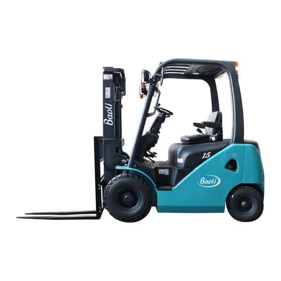
Ⅰ. About F-series forklift truck 1. External view and technical parameter Fig1.1 External view... - Page 8 Technical parameter KION Baoli Manufacturer CPCD20F CPCD25F CPCD30F CPCD35F Model CPQ(Y)D20F CPQ(Y)D25F CPQ(Y)D30F CPQ(Y)D35F Diesel/Gasoline/LPG Power type Rated capacity 2000 2500 3000 3500 Load center 2564 2634 2775 2814 Length to fork face Overall width 1150 1236 Overall 2050 2080...
-
Page 9: Characteristic
2. Characteristic (1) The hydraulic steering device and transverse steering axle makes steering flexible and the turning radius minor. (2) The braking system employs hydraulic brake, makes it possible to manipulate conveniently and brake reliably. (3) Hydraulic transmission type forklift trucks are provided with a drive unit including a hydraulic torque converter and an electron transmission box. -
Page 10: Main Components
4. Main components Fig1.2 1. Outer mast 2. Inner mast 3. Lift chain 4. Lift cylinder 5. Load backrest 6. Fork location pin 7. Lift bracket 8. Fork 9. Driving wheel 10. Tilt cylinder 11. Turning wheel 12. Engine hood 14. -
Page 11: Operation Device And Instrument Panel
5. Operation device and instrument panel Fig1.3 1. Direction control lever 2. Steering wheel 3. Horn button 4. Integrated light and turn signal switch 5. Lifting lever 6. Tilting lever 7. Operating lever, attachment 8. Combination meter 9. Tool kit 10. - Page 12 5.1 Switch (Fig.1.3) Name Operation and attention O (OFF): Engine stop position. Key insertion and withdraw Ignition switch are performed in this position. I (ON): Engine operation position. Locate one position clockwise from O (OFF) position. The intake heater is preheated before starting the diesel forklift.
- Page 13 5.2 Control components (Fig.1.3) Name Operation and attention Lever for shifting between forward and reverse. Direction control lever Forward……………………Push forward (Fig. 1.3-1) Reverse……………………Pull backward The neutral position is halfway between the forward and reverse position. Caution: The engine can’t be started unless the control lever is at the neutral position.
- Page 14 1. The steering wheel position may be adjusted back and Steering wheel adjustment forth. lever 2. Lowering the directional lever at the proper position (Fig. 1.3-15) fixes the steering wheel at that position. 3. After the adjustment, try to move the steering wheel back and forth to see that it is fixed.
- Page 15 5.3 Body components (Fig. 1.2) Name Operation and attention The operator’s seat and seat belt are provided for your Operator’s seat (Fig. 1.2-14) safety. The seat can be moved back and forth for position adjustment while the adjust lever is pulled right. Opening:...
-
Page 16: Ⅱ. Safety Instruction And Operation Of Forklift Truck
It is important for drivers and managers to remember the principle of “first safety” and ensure the safety operation as the description of Operation & Service Manual. Please read this manual thoroughly. This will give you a complete understanding of Baoli forklift truck and you will operate them correctly and safely. -
Page 17: Start And Stop Of The Engine
operation. Check lifting system, actuate the lifting and tilting levers to be certain that the lift bracket moves up and down properly and the mast can be tilted smoothly. Check brake system and steering system for flexibility and reliability. (8) Check the traveling brake: the free stroke of brake pedal is 4-8 mm, when achieving effective brake, the clearance between the front floor and the pedal should be more than 20mm. -
Page 18: Parking And Storing
4. Parking and storing (1) Safe parking (a) Park your forklift truck on a level ground preferably in a wide area. If parking on a slope is unavoidable, press down the parking brake device and block the wheels to prevent accidental roll. The truck is forbidden parking on a steep slope. (b) Park your forklift truck in the area where designated or traffic conditions permit. -
Page 19: Shipping, Loading And Unloading, Slinging And Towing Of Forklift Truck
Perform the following service and checks in addition to the “Daily storage” service: (a) Taking the rainy season into consideration, park the truck at a higher and hard ground. (b) Avoid parking on soft grounds such as asphalted road in summer. (c) Apply antirust oil to the exposed parts such as piston rods and shafts which tends to rust. - Page 20 (a) Use the plate with enough length, width and strength. (b) Pull the parking brake and use jacks to stop the wheel. (c) Fasten the plate on the center of the cabin, there must be no grease on the plate. (d) The left and right height of the plate must be equal to make the loading and unloading smooth.
-
Page 21: Information Of Safety Operation
(4) Daily maintenance should be done before or after using the truck. Anytime you find that the truck is not functioning normally, operation of the truck should be halted and check or repair at once. (5) When the distance between the gravity center of loads and the fork arms is 500mm, the max. - Page 22 tightly the control wheel with two hands; meanwhile, his body must incline in opposite direction of truck’s turning over. (18) Turning, lateral or deflective traveling shall not be taken on a slope. It could cause overturning of the truck, it is very dangerous. On a slope, drive the truck with load forward to ascend and backward to descend.
- Page 23 (31) When travel with load, don’t tilt mast forward, don’t do handling. Don’t brake abruptly to prevent goods from slipping off the forks. (32) It is necessary to brake before tilting the mast forward or backward. It’s also necessary to decelerate and tilt forward slowly so as to prevent the goods from slipping off the forks.
- Page 24 (47) Check the chains periodically to make sure that good lubrication condition exists between the chain elements, the degree of tightness between left and right chain is identical. If the variation value of the chain pitch exceeds 2% standard value, it indicates that the chains have been worn excessively, replace it immediately.
-
Page 25: Caution Plate
The vertical The noise pressure The measured sound The guaranteed level at the operator’s direction power level sound power level Model acceleration mean position value from the seat EN12053 EN12053 2000/14/EC to the operator CPCD20F 85 dB(A) 105 dB(A) 107 dB(A) 0.76 (m/s CPCD25F 86 dB(A) - Page 26 (3) Nameplate of forklift truck (4) Lubrication system (5) Capacity chart (6) Inspections before starting (7) Adjust parking brake...
- Page 27 (8) Use parking brake (9) Add hydraulic oil (10) Add fuel (gasoline) (11) Add fuel (12) Add antifreeze (13) Tyre safety (charging tyre)
- Page 28 (14) Tyre pressure decal (charging tyre) 2-2.5t forklift truck 3-3.5t forklift truck (15) Sling point indication (16) Sling decal (17) Forbid entering into the space behind the mast...
- Page 29 (18) Forbid conveying person (19) Hand caution (20) Fan hurting hand (21) Hood crushing hand (22) Belt pulley thumb hand decal (23) Overturn caution...
-
Page 30: Ⅲ. Periodic Inspection And Servicing
Ⅲ . Periodic inspection and servicing During operating the forklift truck, it is necessary to operate carefully, service and maintain periodically to make the forklift truck keep in good condition. 1. General rules on inspection and maintenance (1) Only use genuine parts when replacing critical parts. (2) Only use genuine or recommended oil when replacing or adding. -
Page 31: Inspection Content
2. Inspection content Walk around inspection Vehicle uprightness Does the vehicle lean to one side or the other? If it, check for a tyre puncture or a problem with the undercarriage. Check for any oil or water leakage on the ground or floor where Beneath the vehicl the vehicle was parked. - Page 32 Engine compartment inspection Level check and supply of engine coolant shall be performed Engine coolant level check and while the coolant is cool. supply 1. With the engine off, open the engine hood and check the engine coolant level in the reservoir tank. Note: The reservoir tank equipped to the radiator automatically supplies the engine coolant when the coolant quantity in the...
- Page 33 Engine oil inspection 1. Park the vehicle on a flat ground. If the vehicle is inclined, the indicated level may be incorrect. 2. The oil level must be checked before starting the engine or at least 3 minutes after the engine is stopped. 3.
- Page 34 1. Depress the brake pedal fully, and check the floor clearance Brake pedal inspection (clearance between the pedal and floor is not fewer than 110mm) 2. Make sure that the pedal does not go any further when it is kept depressed. 3.
- Page 35 Start the engine and warm it up sufficiently. Engine inspection 1. Check each meter and warning lamp to see there is no abnormality. 2. Check if the engine is generating abnormal sound or vibration. 3. Check the exhaust gas color to see it is normal. Colorless or light blue exhaust indicates complete combustion;...
-
Page 36: Periodic Replacement Table
Before garaging the vehicle Remove dirt from all vehicle components and then perform the following. 1. Inspect for oil or water leakage. 2. Inspect each component for warping, scratches, dents or cracks. 3. Clean the air filter element and lubricate parts as required. 4. -
Page 37: Lubrication Chart
4. Lubrication chart Ⅰ ) Chain Inspect every 8 hours (daily) Ⅱ ) Differential gear Inspect every 40 hours (weekly) Ⅲ ) Front wheel bearing Inspect every 250 hours (6 weeks) Ⅳ ) Brake fluid cup Inspect every 1000 hours (6 months) Ⅴ... -
Page 38: Weekly Maintenance
Weekly maintenance Inspect the items below in addition to the preoperation items. Please inspect the vehicles thoroughly every week to insure safety and pleasant working conditions. Weekly (40-hour) inspection items Air cleaner clean Fan belt inspect Torque converter oil level check Bolts and nuts retighten... - Page 39 Follow the steps below. 1. Try to smell leak. 2. Look for leak. 3. Touch possible leak. See the nearest Baoli dealer upon finding leak and have them repair tank immediately. Caution: Never perform do-it-yourself welding or other repair work for...
-
Page 40: Self Service
6. Self service Prepare tools and jack necessary for replacing or repairing Replacing or repairing tyre tyres. 1. Front wheel .Stop the vehicle on a level, hard surface and shut down the engine. All loads should be unloaded from the vehicle. .Press the parking brake pedal and block the wheels. - Page 41 If a lamp does not come on or an electrical device does not Fuse replacement function, the corresponding fuse may be blown. Check the fuse for each device. The lighting location on the fuse box is blown fuse when electrified. The fuse box is located in the front left as seen from the opened engine hood.
-
Page 42: Recommended Oil And Grease For Forklift Truck
Terminals: Maintaining the battery 1. A loose or corroding terminal causes failure in connection. Eliminate white powder, if noticed on the terminal, by pouring warm over it to disable and then grease the terminal. 2. Remove the terminal, if it is extremely corroded, from the battery to brush off the corrosion using a wire brush or sandpaper. - Page 43 Brand Recommended General standard Viscosity Domestic Caltex Mobil Shell Esso Oil level Product temperature Asses “Viscosity Grade” Shell X100 Esso extra motor oil according to environment Shell Helix temperature Gasolin API SG RPM Delo 400 oil API SJ Mobil super S Esso Superflo -10℃~+30℃...
-
Page 44: Ⅳ. Construction, Principle, Adjustment And Maintenance Of Forklift Truc
Ⅳ . Construction, principle, adjustment and maintenance of forklift truck In order to keep good condition of your truck, you must have an intimate understanding of the construction, principle, adjustment and maintenance of the forklift truck. When finding damage or fault with the truck, stop operating the truck and inform a professional serviceman. -
Page 45: Inspection And Adjustment Of Engine
Parallel table for engine and forklift model which is coincidence and stuck with CE label: The guaranteed Sound power Exhausting CE CONFORMITY Engine model Truck model level LwA(dB) 2004/26/EC 2006/42/EC 2000/14/EC CPCDF ISUZU C240PKJ StageⅢ A 20/25/30-W1 CPCDF 4TNE92 StageⅢ A 20/25-Y1 Yanmar CPCDF... -
Page 46: Hydraulic Drive Unit
to moderate speed, after the cooling system cooled then turn to idle speed, loosen cap slowly to allow steam to escape, the cap can be removed. After that, make sure the cap is tightened securely. (2) Check the radiator coolant reservoir fluid level. It should between FULL and LOW mark. - Page 47 (3) One-way clutches in the torque converter are used to increase the efficiency for power transmission. (4) High quality oil filters is helpful to increase the life of the torque converter. Fig2.1 Hydraulic drive unit 1. Forward clutch 18. Safety valve cover 35.
-
Page 48: Reducer And Differential
2.2 Reducer and differential (Fig2.2) The reducer located in the front of the transmission is used to reduce the speed and increase the torque from the output shaft of the transmission and transfer them to the differential. It consists primarily of a small spiral bevel gear assembled on the output shaft and a pinion shaft splinted with a big spiral bevel gear. -
Page 49: Torque Converter
2.3 Torque converter (Fig2.3) The torque converter mainly consists of an impeller, a turbine and an idler pulley. The liquid, from the impeller driven by an input shaft, is jetted along its leaves to leaves of the turbine to transmit the torque to the output shaft (Mechanical energy is changed into kinetic one). -
Page 50: Hydraulic Circuit
2.4 Hydraulic circuit (Fig 2.4) After the engine is started, the charging pump inhales the oil from the oil tank. The pressure oil from the pump serves two parts for hydraulic clutches and torque converter. The oil necessary to operate the hydraulic clutches is divided into two circuits through the pressure valve (set pressure of 1.1-1.4MPa): one circuit flowing to the torque converter via. -
Page 51: Troubleshoot
2.6 Troubleshoot (1) Insufficient power Parts Problem Possible cause and remedy A. Too low oil pressure 1. Lower oil level Check oil level and add oil 2. Air entering in resulting from loose Check connection or oil pipe. connections Retighten each connection or Torque replace seal. - Page 52 (3) Noisy gear box Parts Problem Possible cause and remedy 1. Elasticity plate is broken Check noise and replace elasticity plate. 2. Damaged or worn bearing Check or replace 3. Gear is broken Check or replace Torque converter 4. Spline is worn Check or replace 5.
-
Page 53: Drive System
3. Drive system Type Front wheel drive, axle body and frame fastened together, fully floating type 2t, 2.5t 3.5t Forklift truck Single tyre (2) Double tyres (4) 28×9-15-12PR 28×9-15-14PR Tyre size 7.00-12-12PR Rim size 5.00S-12D 7.00WFB-15 Tyre 0.84MPa 0.80MPa pressure Notice: For the difference of manufacturers’... - Page 54 Install the inner rim and gasket inside the outer rim and assemble the outer rim and inner rim. Pay attention to the following points: (a) Put the air valve rod in the notch of the rim and make it face outside. (b) Make the tops of the rim mounting bolts face outside.
- Page 55 Fig3.2 Add grease Fig3.3 Measure starting torque Structure of rim bolt Fig3.4 Wheel assembly 1. Tyre 4. Inner rim 7. Spring washer 2. Air valve 5. Outer rim 8. Nut, rim 3. Bushing 6. Rim bolt...
-
Page 56: Troubleshoot
3.3 Troubleshoot Problem Probable cause Remedy Connecting bolt of reducer is loose or worn Tighten or replace shim Oil leaks from the reducer Blocked air hole Clean or replace case Worn or damaged oil seal Replace Worn or damaged gear Replace Worn or damaged bearing Replace... -
Page 57: Brake System
4. Brake system Front two-wheel braking, internal expansion, Type of brake system hydraulic type Pedal ratio 5.66 Master cylinder bore 19.05mm Wheel brake 2t, 2.5t 3t, 3.5t Type Duo-servo type with parking brake Operating cylinder bore 28.58mm Size, friction pieces (L×W×T) 324×60×7mm 348×76×8mm ×4... -
Page 58: Wheel Brake
cylinder is pressurized by the return spring, returning into the master cylinder through the check valve. With the piston in its original position, the brake fluid in the master cylinder flows into the reserve tank through the return port. The brake fluid in the brake pipelines and operating master has a residual pressure proportioned to the set pressure of the check valve, which makes each operating cylinder piston cup securely seated to prevent oil leakage and eliminates a possibility of air locking when the truck is sharply braked. - Page 59 Fig4.2 Wheel brake 1. Spring 8. Return spring 15. Spring pull rod 2. Cup 9. Adjusting lever 16. Parking pull rod 3. Piston 10. Secondary brake shoe 17. Parking push rod 4. Cylinder body 11. Clearance adjuster 18. Operating cylinder 5.
-
Page 60: Operating Device Of Parking Brake
Fig4.3 Clearance self-adjuster 4.4 Operating device of parking brake The parking brake is of a lever type. Open the second cap on the right of the meter bracket covering, the brake force can be adjusted with the parallel-driver. Brake force adjustment: When you turn the adjuster clockwise, the force increases, otherwise, when you turn the adjuster counterclockwise, the force decreases. -
Page 61: Inspection Of Wheel Brake
4.5 Inspection of wheel brake Inspect all parts to make sure if there’re any worn or damaged parts. If necessary, repair or replace with new one. (1) Check the operating cylinder body’s inner surface and the piston periphery surface for rusting. Then, measure the clearance between the piston and cylinder body: Specified clearance: 0.03 to 0.10 mm Maximum clearance: 0.15mm (2) Visually check the piston cup of the operating cylinder for damage or deformation. -
Page 62: Troubleshoot
4.6 Troubleshoot Problem Probable cause Remedy 1.Fluid leaks from brake system Repair 2.Maladjustment of brake shoe clearance Adjust the adjuster 3.Brake overheating Check for dragging Poor 4.Poor contact between brake drum and friction Readjust braking piece 5.Foreign matter adhered on friction piece Repair or replace 6.Foreign matter mixed in brake fluid Check brake fluid... -
Page 63: Steering System
5. Steering system 2t, 2.5t 3.5t Steering system Rear wheel powered steering Type of steering unit Cycloid gear type powered steering unit Model of steering unit BZZ1-100 (sealed by taper ring) Type Double-action piston type φ70 Cylinder bore Steering φ50 cylinder Diameter of piston rod Stroke... -
Page 64: Hand Wheel
5.1 Hand wheel Hand wheel is operated in normal way, that is to say, when turning the hand wheel right, the truck will turn right. When turning the hand wheel left, the truck will turn left. The rear wheels of the forklift truck are steering wheels, which make the tail section of the truck swing out when turning. -
Page 65: Inspection After Reassembling The Steering System
5.3 Inspection after reassembling the steering system (1) Check the force when turning the steering handwheel to right and left until it can’t be turned any more to see if they are identical each other and check the operation if the steering handwheel for smoothness during above operation. -
Page 66: Steering Axle
5.5 Steering axle The steering axle is of section-boxed welded construction type (Fig5.3). It includes axle body, steering cylinder, tie rod, steering knuckles and steering wheels. The steering axle is of cranks and slider mechanism. The cylinder piston rod pushes the knuckle steering through tie rod, causing wheel’s deflection and truck’s steering. - Page 67 5.5.1 Steering cylinder The steering cylinder is of double-action piston type. The seal unit consists of the supporting ring and O-ring, Yx-ring seal is adopted between the cylinder cover and the piston rod. The cylinder is fitted on the steering axle through two sides cylinder covers. Fig5.4 Steering cylinder 1.
- Page 68 manually the hub for 3~4 turns to ensure its smooth rotation with a specified torque of 2.94~7.8N.m. (7) If the torque value necessary to rotate the hub is more than the specified one above-mentioned, screw out the castle nut for 1/6 turn and measure the torque value then.
-
Page 69: Hydraulic System
6. Hydraulic system Type Gear pump Hydraulic oil pump Displacement 32 ml/r Type Two-pool type with relief valve, flow divider and tilt valve Setting 17.5MPa pressure Control valve Dividing 7 MPa (2,2.5t) / 9 MPa (3t) / 10.5 Mpa (3.5t) pressure Flow rate 11L/min (2-2.5t) - Page 70 1. Pump body 2. Driving gear 3. Driven gear 4. Front cover 5. Rear cover 6. Lining plate 7. Seal ring 8. Ring 9. Oil seal 10. Snap ring Fig6.1 Hydraulic pump Fig6.2 Control valve...
- Page 71 6.3.1 Relief valve and flow divider (see Fig6.3) The relief valve consists of main valve A and proceeding valve B. When the spool of the control valve is operated, chamber Q linked with the operating cylinder is filled with high pressure oil. The high pressure oil affects proceeding valve B through throttle hole D and E.
- Page 72 6.3.2 Setting pressure of the relief valve The pressure of the relief valve has been set before delivery. Don’t adjust the pressure at will, for it will bring danger for system and safety. If the oil pressure is different with standard value, according to the measure method specified in JB/T3300, specialized servicemen adjust the pressure as follows: (a) Screw out the measured hole plug from the inlet port of control valve and install the oil-pressure gauge (20MPa) on it.
-
Page 73: Hydraulic Oil Circuit
6.4 Hydraulic oil circuit (Fig6.5) The oil from the hydraulic pump comes to the control valve first and there is divided by the flow divider into two parts, one being sent to lift cylinder or tilt cylinder, and another to the power steering unit in constant flow rate to operate the steering cylinder. With the spools of the lift and tilt spool valves in neutral position, the oil from the pump directly returns to the tank through the passage in the control valve. -
Page 74: Lift Cylinder
6.5 Lift cylinder (Fig6.6) The lift cylinder is of single-action piston type. It consists of cylinder body, piston rod, piston and cylinder head etc. The bottom of the cylinder is connected with the cylinder supporter of the outer mast by bolts and pins, while its top (i.e. piston rod head) is connected with the upper beam of the outer mast. -
Page 75: Flow Regulator Valve
6.6 Flow regulator valve The flow regulator valve, located in the lift cylinder circuit to limiting the descending speed of loaded forks, has the construction as shown in Fig6.7. When the lift spool valve is placed in the “lift” position, the oil from the control valve flows through the oil chambers A and B, oil holes C, D, E and F, and the chamber G to the lift cylinder without any regulation. -
Page 76: Tilt Cylinder
6.7 Tilt cylinder (Fig 6.8) The tilt cylinder is of double-acting type. Each truck has two cylinders which are installed on two sides of the mast, their cylinder base are connected with frame with pins while their piston rod ends are connected with the outer mast channels. The tilt cylinder assembly consists of piston, piston rod, cylinder body, cylinder base, guide sleeve and seals. -
Page 77: Troubleshoot
6.8 Troubleshoot If the hydraulic system occurs trouble, find out the possible cause according to the following tables and repair it. (1) Control valve Problem Possible cause Remedy Disassembly and clean, Spool is held up renew oil Slide surface broke down Replace spool Lower oil pressure and lower oil amount of the... - Page 78 (2) Hydraulic oil pump Problem Possible cause Remedy Lower oil level in oil tank Add oil up to specified oil level Oil can not be pumped out Blocked pipe-line or oil filter Clean or replace oil if necessary Lining plate broken down Wearing broken down Replace Seal ring, bushing or snap ring...
-
Page 79: Lifting System
7. Lifting system Fig7.1 Mast 1. Outer mast 4. Tilt cylinder 7. Lift bracket 2. Inner mast 5. Load backrest 8. Fork 3. Lift cylinder 6. Lift chain 7.1 General description The lifting system is the type of lifting and descending vertically with the two-stage rollers. - Page 80 7.1.1 Inner and outer mast The inner and outer masts are welded parts. The bottom of outer mast is connected with the drive axle through supporting. At the outside middle of outer mast, it is connected with the frame by the tilt cylinder. The mast can be tilt forward and backward by operating the tilt cylinder.
-
Page 81: Maintenance And Adjustment
Fig7.2 Roller position Notice: (a) Adjust the side roller clearance for 0.5mm. (b) Apply lubricating grease on the surface of main roller and interface of mast. 7.2 Maintenance and adjustment 7.2.1 Adjustment of lift cylinder (Fig7.3) When replace the lift cylinder, inner mast or outer mast, we shall readjust the stroke of the lift cylinder as following: (1) Install the piston rod in the upper beam of the inner mast without shims. - Page 82 7.2.2 Adjustment of lift bracket (1) Let the truck parking on the horizontal ground and make the mast vertical. (2) Lower the forks on the ground, adjust the nut for the end nipple of the upper chain and make a distance A between the main roller and the lift bracket. Capacity A mm 2t~2.5t...
- Page 83 7.2.4 Replace rollers (Fig7.6) (1) Use the same way as 7.2.3 to disassemble the lift bracket from the inner mast. (2) Let the truck parking on the horizontal ground and wedge up the front wheels for 250mm to 300mm. (3) Apply the parking brake and wedge up the rear wheels. (4) Disassemble the bolts which fasten the lift cylinder and the inner mast.
-
Page 84: Electric System
8. Electric system 8.1 General description The electric system for this forklift truck is single wire system with minus earth. It mainly consists of the following systems: (1) Charge system This system contains generator, battery, charging indictor, etc. It supplies current for all the electric appliances. -
Page 85: Brief Explanation For Operation
8.2 Brief explanation for operation (1) Starting There is a starting protection circuit in the control box for the safety of the forklift truck. You must shift the direction switch at the neutral position before starting the engine. Otherwise, you can not start the engine. Turn the key switch clockwise to the Ⅰ... -
Page 86: Instructions Of Meter Panel
(7) Oil pressure signal Before starting the engine, put the key switch to theⅠ (ON) position and the oil pressure warning lamp lights. After engine starting, the oil pressure warning lamp is automatically off. If this lamp lights while the engine is working, it indicates low engine oil pressure and you must stop working and check as soon as possible. - Page 87 (2) When the meter is during self-check, the LCD displays Baoli welcome. When running normally, the LCD displays running well.
- Page 88 a. Indicate the remaining fuel in the tank, total with 6 scales. b. Switch on the meter, the fuel indicating needle will return to E position, then it will run to corresponding position with fuel capacity, and stop turning until cutting off the power. Caution: After adding oil or turning on the ignition switch, the indicating needle will stop turning after a...
- Page 89 If lamp does not go out, the generation system may be faulty. Please ask a Baoli dealer immediately for inspection and repair. Switch on the meter, the initial condition of torque (11) Warning lamp, converter oil temperature (begin from 65℃) will...
- Page 90 (15) Warning lamp, lubrication system is faulty. Stop the operation engine oil pressure immediately and ask a Baoli dealer for inspection and repair. Note: The “warning lamp of engine oil pressure” does not indicate the oil level.
-
Page 91: Principle Diagram Of Electrical System
8.3.2 Cautions (1) Forbid wetting the meter. When washing the truck, don’t let water into the meter, if it happens, clean it with dry cloth. (2) Don’t pull the plug of the meter and harness regularly to avoid poor contact. (3) Forbid impacting or scratching the meter strongly. - Page 92 Central control box 00 Power(-) 01 Power, horn 02 Power, lamp 03 Power, meter 04 Power, switch 05 Switch, turning lamp 06 Power, ignition switch 07 Switch, light 08 Switch, start 09 Power, headlamp 10 Preheating indicating 12 Main power 13 Preheating fuse 14 Starter 15 Optional power 1...
- Page 93 Central control box 00 Power(-) 01 Power, horn 02 Power, lamp 03 Power, meter 04 Power, switch 05 Switch, turning lamp 06 Power, ignition switch 07 Switch, light 08 Switch, start 09 Power, headlamp 10 Preheating indicating 12 Main power 13 Preheating fuse 14 Starter 15 Optional power 1...
- Page 94 Central control box 00 Power(-) 01 Power, horn 02 Power, lamp 03 Power, meter 04 Power, switch 05 Switch, turning lamp 06 Power, ignition switch 07 Switch, light 08 Switch, start 09 Power, headlamp 10 Preheating indicating 12 Main power 13 Preheating fuse 14 Starter 15 Optional power 1...
- Page 95 Fig8.3-1 Diagram of harness (4JG2 engine)
- Page 96 Fig8.3-2 Diagram of harness (Dachai 498 engine)
- Page 97 Fig8.3-3 Diagram of harness (Xinchai 498engine)
- Page 98 Fig8.3-4 Diagram of harness (Yanmar 4TNE98 engine)
-
Page 99: Note
NOTE... - Page 101 KION Baoli (Jiangsu) Forklift Co., Ltd. Service Hotline: 400-828-2789 Tel: +86 523 8461 6148 Fax: +86 523 8461 6126 P.C.: 214500 Add: No. 8 Xinzhou Road·Economic Development Zone·Jingjiang·Jiangsu·China www.baoli-mh.com * We reserve the right to make any changes or modifications of pictures and specifications in this manual without giving previous notice and without incurring any obligation.
Need help?
Do you have a question about the F Series and is the answer not in the manual?
Questions and answers