Table of Contents
Advertisement
Advertisement
Table of Contents

Related Manuals for Baoli KBET15


Summary of Contents for Baoli KBET15
- Page 2 https://www.truck-manuals.net/ Maintenance Manual...
- Page 3 KION Baoli (Jiangsu) Forklift Co., Ltd KB-2017-08-V1.0...
-
Page 4: Product Information
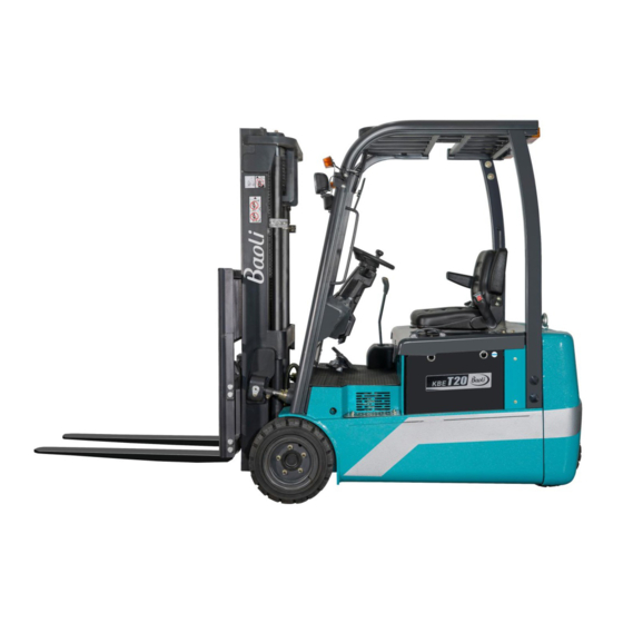
Product information Instruction and maintenance manual This chapter gives information taken from the instruction and maintenance manual, considered as of interest for the assistance technician. NOTE Consult the truck instruction and maintenance manual for detailed information on the use of the truck. General Forklift Description The model described in this manual is an electric forklift with seated operator and counterbalanced forks. - Page 5 Definition of travel direction https://www.truck-manuals.net/ Forwards Backwards Left Right...
- Page 6 Overall dimensions for four-wheel truck...
- Page 7 three-wheel truck technical data...
- Page 8 Note: E=Environmental protection solid tyre; S=solid tyre ; P=Pneumatic tire 1) With side shift ,+17mm 2) For alternative wheels, see table. 3) battery options (capacity/weight): 505AH/595Ah-810KG/920KG The values shown refer to standard outfits; they are indicative only and not binding. Three-wheel truck tyre characteristics WHEELS Environmental...
- Page 9 forks = 1400 mm max. Rated capacity height free-lift height mast load center max. height closed height with without with type 500mm height carriage carriage carriage 1.5T 1.8T 2500 1745 3542 2700 1845 3742 3000 2005 4042 Stand 1500 1800 3250 2120 4292...
- Page 10 2500 1757 3540 2700 1857 3740 3000 2000 2007 4040 Stand 3300 2157 4340 wide- 3500 2257 4540 view 4000 1800 2557 5040 2500 1757 3540 1167 2700 1857 3740 1267 Full 3000 2000 2007 4040 1417 1007 free 3300 2157 4340 1567...
- Page 11 subtract 150kg with side shifter Lift types: • SX: Simplex lift • DX GAL: Duplex lift with free lifting • TX GAL: Triplex lift with free lifting • WITH SLI: with side shift • WITHOUT SLI: without side shift SES: Single superelastic tyres PN: Pneumatic tyres TWIN: Twin tyres...
-
Page 12: Tyre Inflation Pressure
Tyre inflation pressure Type AXLE SIZE PRESSURE Front 18×7-8 1.5/1.8T Rear 16×6-8 Front 200/50-10 2.0T Rear 16×6-8 Lamps Front light 12V-55W Direction indicators lights 12V-21W Breadth indicators lights 12V-5W Tail and stop lights 12V-21W Reversing lights 12V-10W Flashing beacon 12V-2W Battery dimensions and weights Truck type Voltage V... -
Page 13: Internal Accessibility
Internal accessibility To access the internal remove the floor, 4 remove bolts, removal of multi-way valve cover parts of the truck (battery), proceed as NOTE follows: The battery cover is held open by 1) upward, open the battery a gas spring . cover, 2 ) remove bolts, open the 1):To close the cover, follow the electrical cover, 3) remove bolts,... -
Page 14: Safety Features
Safety features Sollevatore: 1. Load carrying grate 2. Fork stop latches 3. Fork retaining device 4. Fork carriage retaining device 5. Chain retaining device 6. Chain tension rod retaining device 7. Emergency stop button 8. Shear protection net... - Page 15 10. "Seat switch" microswitch that blocks operation of the truck when the operator is not seated on the driver’s seat 11. Restraining belt 12. Overhead guard 13. Alarm horn 14. Reverse gear warning buzzer 9. flashing beacon...
- Page 16 The forklift is normally transported by truck and train complete with hoist. If the forklift’s dimensions exceed the NOTE max. clearance size allowed, it is These devices most be checked transported disassembled. The daily, as described in Chapter 4. sales network is in charge of the disassembly and reassembly operations.
-
Page 17: Forklift Towing
Forklift towing During the towing operation, the in order to perform the steering and operator must be on board the truck braking operations. NOTE Use non-metallic cables for towing Version with reversing on the steering wheel Before towing models with reversing that this lever (1) is in the central lever on the steering wheel, check position. -
Page 18: Loading And Unloading The Truck
Loading and unloading the truck Use an inclined plane or movable loading ramp to load and unload the truck. If the truck is not operational or does not have the battery, lift it as described below. - Page 19 Use a crane with a suitable lifting capacity for the weight of the truck, indicated on its designation plate. Also take into account the weight of the mounted battery (if applicable), consulting the relevant designation plate. The lifting operations must be performed by qualified personnel.
-
Page 20: Safety Precautions
Safety precautions Description of safety symbols This document gives the danger warnings Each of such danger warnings consists of a graphic symbol, followed by a description danger consequences, description of how it can be avoided. The types of warnings used are described below. This warning indicates serious risks for the safety of the operator and maintenance staff. - Page 21 Failure to observe the safety prescribed by the maintenance or provisions can cause serious repair instructions. harm to technical staff and to • All service actions must be the truck. carried out with maximum During maintenance and repair care and attention. procedures, scrupulously follow the prescriptions indicated below •...
- Page 22 • To avoid improper use or use in unsafe conditions, label all controls to mark that repairs are in progress. • Do not leave the machine unattended with parts in movement. • Immobilise the machine and all equipment or parts that are subject to maintenance while raised, or which could accidentally move.
- Page 23 • When carrying out operations tow bar, ropes or chains from beneath the truck, always working under tension. use a maintenance well or a • To move a machine that has bridge crane of adequate broken down, use a trailer or a capacity.
-
Page 24: Electrical System
the fluids used are always use adequate inflammable. protection (gloves, goggles, • Never pour petrol or diesel oil etc.). Do not use chains r ropes into open, wide or low that are worn or bent for lifting recipients because of the risk or pulling. - Page 25 before proceeding with the work. • Refer to the specific Instruction and Maintenance Manual of the drive battery. • Before any operation, check that no elements are short circuited: eliminate such short circuits before proceeding with the work. • For electric heaters, battery chargers and similar appliances, use only effectively earthed auxiliary power...
-
Page 26: Hydraulic System
Hydraulic system Disconnections and reconnections Small high pressure jets of oil can penetrate the skin. Before removal and Penetration of the skin by installation of any component, hydraulic oil under pressure disconnect the relative plug spurting from the hydraulic from the battery outlet. system is dangerous. -
Page 27: Safety Regulations Relative To Operating Materials
Safety Regulations Relative to Operating Materials Rules for handling and area in question must be thoroughly cleaned. disposing of operating • The replaced parts must materials. always be disposed of in accordance with the ENVIRONMENT NOTE anti-pollution laws. Improper use and disposal of operating and cleaning materials can cause serious damage to the environment. - Page 28 under pressure from the forklift’s hydraulic system is dangerous. If this type of lesion should occur, contact a doctor immediately.
-
Page 29: Battery Acid
NOTE Small high pressure jets of oil For greater information, consult can penetrate the skin. Look the specific battery manual for any leaks using a piece of that comes with the battery. cardboard. ENVIRONMENT NOTE Battery Acid The batteries contain •... - Page 30 Maintenance Preliminary operations before commissioning Below are listed the operations • Check the inching pedal that must be performed on the linkage, fan belt tension, forklift before delivering it to the handbrake tension and adjust customer: if necessary. • General test of the forklift. •...
- Page 31 Synoptic Table of Maintenance Operations Hours Operation Everyday Check wheel nut tightening Parking brake check · Chain tension check and adjustment · Check hydraulic tank oil level · Cleaning of the electronic panel · Lubricating the steering axle Fork carriage guide lubrication ·...
-
Page 32: Supply Table
ENVIRONMENT NOTE Proceed as follows at each lubrication operation: • Follow the safety precautions for the lubricant; • Before lubricating, carefully clean the component to be lubricated; • Use suitable binders if the lubricating product should spill; • Keep the product in a suitable and compliant place, as per the instructions supplied with the product;... - Page 33 1.5T/1.8T ATF220 gearbox 2.0T SAE-80W Lubricant Chains STRUCTOV Oil-immersed brakes 0.2 L...
-
Page 34: Diagnostic Software
Diagnostic software Connection between the diagnostics PC and the forklift The diagnostics PC connects to the forklift through the SME interface cable. The connection can be performed on all modules. The connection between PC and forklift must be performed with the forklift turned off. - Page 35 Software The software to be used for the parameterization and diagnostics is EYEPLUS. Instructions: • Connect the PC to one of the electronic modules using the interface cable. • Access the software through the relative icon. • If EYEPLUS software installation is successful, starting the application from Windows “Programs”...
- Page 36 Starting EYEPLUS application, your system memory is read to in order to know truck model and to properly customize all menus, because more than one lift truck model can be available. For example see drive motor menu in case of twin drive motors (Fig.11) and in case of single drive motor (Fig.12).
- Page 37 In case of faults during a serial communication data flow, any submenu is aborted and main menu front panel is reinitialized. PASSWORD INSERTION Selecting Password mode from menu-bar, you access Supervisor mode (Fig.7), inserting the right password (Fig.5). In case of wrong password insertion message Fig.6 becomes visible.
- Page 38 In Supervisor mode, you can access these further menus: “ Calibration ” “ Flash ” “ Password ” menu disappears from menu-bar. In case of faulty serial communication, main menu front panel is reinitialized as follows (Fig.8)
- Page 39 Notice : “PANEL BLANK” message is used to distinguish case of not programmed flash memory, so Flash menu is obviously active. You can select active menus directly from main panel menu bar (any greyed menu is not accessible in that moment); you can also access present sub panels with a further selection by a pop-up...
- Page 40 NOT ACTUAL SOFTWARE / EEPROM CRC FAULT A CRC alarm message is visualized both in case of failed EEPROM memory writing and of using a software version without the CRC control procedure. Pressing the visualized button, you can load in EEPROM default values: if you don’t execute this procedure, calibration functions are inhibited.
- Page 41 SUBMENUS “Print” function is accessible from many of listed submenus: you can send active front panel image to printer or save it on file; in that case destination directory is <EYEPLUS PATH>\EYEPLUS\images. Notice: if more than one window is in use, only the one relative to the inner submenu is active and all others work in background.
- Page 42 DRIVE (TRACTION) TEST MENU Following items appear in Drive menu front panel for twin motor applications: • Accelerator pedal voltage • Pedal brake pressure (in bar) • Drive motors phase currents: you can select current phase from pop-up menu • Both modules temperature: you can select measure unit between °C and °F.
- Page 43 Following items appear in Drive menu front panel for single motor applications: • Accelerator pedal voltage • Pedal brake pressure (in bar) • Drive motor phase current: you can select current phase from pop-up menu • Module temperature: you can select measure unit between °C and °F. Notice: temperature above 60°C is signalled by a red colour;...
- Page 44 PUMP TEST MENU Following items appear in Pump menu front panel: • Voltage on lift command circuit • Hydraulic lift circuit pressure • Pump motor current : you can select current phase from pop-up menu • Module temperature: you can select measure unit between °C and °F.
- Page 45 BATTERY TEST MENU Following items appear in Battery menu front panel: • Battery and inverter voltages • Battery charge level • Code, description and level of active more serious alarm for both microprocessors. If there is more than one alarm of same level, the latest is visualized.
- Page 46 TIMERS TEST MENU Following items appear in Timers menu front panel: total inverter working hours, drive motor and pump motor hour meter and odometer readings.
- Page 47 CALIBRATION By a pop-up menu, you can access following calibration functions: • “ Battery “: Battery reset voltage calibration (Fig. 16) (**) • “ Timers “: Timers calibration (Fig. 17) • “ Steering “: Steering sensor (Fig. 18) • “ Pedal “: Pedal accelerator calibration (Fig. 19) (**) •...
- Page 48 Notice: a confirmation is asked to quit a calibration menu without saving changes. Notice: you can’t set a value out of fixed limits. Such a case is signalled by the message “OUT OF LIMIT”. Notice: see Appendix A to find further explanation about programmable parameters meaning.
-
Page 49: Standard Version
BATTERY RESET VOLTAGE CALIBRATION (**) Standard version In that menu front panel, you can find following data about battery reset voltage: description, actual value, new value you want to set, measure unit, default value, minimum and maximum settable values. You can execute following operations: Load default value: 1. - Page 50 Optional version You can find a further parameter to be calibrated: discharged battery voltage; if battery voltage is less than this value, the corresponding alarm appears on display. This parameter is visualized on front panel as battery reset value and also calibration procedure is the same.
- Page 51 TIMERS CALIBRATION In that menu front panel, you can find following data about timer parameters: description, actual value, new value you want to set, measure unit, default value, minimum and maximum settable values. You can execute following operations: Load default value: Press DEFAULT button;...
- Page 52 STEERING SENSOR CALIBRATION There are following data about steering parameters: description, actual value, measure unit, default values, minimum and maximum settable values. Pressing SAVE button, selected parameter VALUE data field is updated with steering sensor actual voltage; if this value is out of permitted range, you cannot calibrate it.
- Page 53 Standard version There are following data about accelerator parameters: description, actual value, measure unit, default values, minimum and maximum settable values. Pressing SAVE button, selected parameter VALUE data field is updated with pedal sensor actual voltage; if this value is out of permitted range, you cannot calibrate it.
- Page 54 Optional version There is a second pedal sensor. Calibration procedure is like standard one, except that START led present (Fig.18) turns ON only after software verifies that the voltages on both pedal sensors are equal to Vmin + 0,5 V voltage, obtained slowly pressing accelerator pedal.
- Page 55 LIFT CALIBRATION There are following data about lift parameters: description, actual value, measure unit, default values, minimum and maximum settable values. Pressing SAVE button, selected parameter VALUE data field is updated with lift sensor actual voltage; if this value is out of permitted range, you cannot calibrate it.
- Page 56 E/S/H PARAMETERS AND L1, L2 ,L3 LIMITS CALIBRATION In that menu front panel, you can find following data about ESH parameters: description, actual value, new value you want to set, measure unit, default values for E, S, and H operating mode, settable per cent values for parameters in L1, L2, L3 operating mode.
- Page 57 If “programmable working” section is disabled, and you select one of L1, L2 or L3 operating modes, a message will advise user and E operating mode will be forced . If “programmable working” section is enabled, pressing MODIFY LIMITS button you enter Fig.22 window.
- Page 58 STEERING PARAMETERS CALIBRATION In that menu front panel, you can find following data about steering parameters: description, actual value, new value you want to set, measure unit, default values minimum and maximum settable values. You can execute following operations: Select default value: 1.
- Page 59 PROGRAM SERVICE CALIBRATION To modify assistance interval, you have to enable apposite function. You can execute following operations: Change actual value: 1. Set button INCREASE properly to select if increase or decrease service interval 2. Change assistance interval value using HOURS INCREASE pop-up menu 3.
- Page 60 DRIVE MOTOR PARAMETERS CALIBRATION (**) Standard version In that menu front panel, you can find following data about drive motor parameters: description, actual value, new value you want to set, measure unit, default values minimum and maximum settable values, actual value in percent. You can execute following operations: Select default value: 1.
- Page 61 Notice: You can also choose if visualize on display one of the following: • odometer indication • time meter • weight of the load on the forks ( only after weight sensor calibration ) Optional versions You can find further parameters to be calibrated ( they obviously depend on application): diameter of tires, starting temperature motors fan, braking ramp, speed after stop on slope, acceleration ramp limitation, inversion ramp limitation, release ramp limitation.
- Page 62 PUMP MOTOR PARAMETERS CALIBRATION In that menu front panel, you can find following data about pump motor parameters: description, actual value, new value you want to set, measure unit, default values minimum and maximum settable values, actual value in percent. You can execute following operations: Select default value:...
- Page 63 CRITICAL HEIGHT: SPEED LIMITS CALIBRATION You can set maximum speed of pump and drive motors in case of a fork height superior to critical one (that condition is signalled by two switches present on lift truck forks) In that menu front panel, you can find following data about critical maximum speeds: description, actual value, new...
- Page 64 WEIGHT SENSOR CALIBRATION (OPTIONAL MENU) In that menu front panel, you can find following data about parameters: description, actual value, measure unit, default values, minimum and maximum settable values. Pressing SAVE button, visualized pressure value is saved on actually selected parameter. You can execute following operations: Select default value:...
- Page 65 There are following data about brake pressure sensor: description, actual value, measure unit, default values, minimum and maximum settable values. Pressing SAVE button, selected parameter VALUE data field is updated with brake sensor actual voltage; if this value is out of permitted range, you cannot calibrate it.
- Page 66 HYDRO THRESHOLD CALIBRATION (OPTIONAL MENU) In that menu front panel, you can find following data about hydro thresholds parameters: description, actual value, new value you want to set, measure unit, default values minimum and maximum settable values. First threshold fixes rpm value that makes truck speed pass from idle speed to steering one;...
- Page 67 CAB LIFT SPEED CALIBRATION (OPTIONAL MENU) In that menu front panel, you can find following data about cab lift speed: description, actual value, new value you want to set, measure unit, default values minimum and maximum settable values. You can execute following operations: Select default value: 1.
- Page 68 TRUCK SETUP (OPTIONAL MENU) (**) Standard version In that menu front panel, you can find following data: parameters description, actual status (ON or OFF), new status you want to set, and default status. You can execute following operations: Select default value: 1.
- Page 69 PLIERS CALIBRATION (OPTIONAL MENU) (**) In that menu front panel, you can read actual measured value for pliers circuit pressure and know which of 1st, 2nd or 3rd setup pressure level is selected ( see three green leds). Another green led shows if your system is working in automatic or in manual mode: Manual mode: a switch...
- Page 70 You can execute following operations: Select default value: 1. Press DEFAULT button ; NEW data field will be automatically updated with default value. 2. Press SAVE button and confirm; OLD data field will be updated. Change actual value: 1. Insert changed value in NEW data field 2.
- Page 71 BACKING MODE PARAMETERS CALIBRATION (OPTIONAL MENU) In that menu front panel, you can find following data about backing mode parameters: description, actual value, new value you want to set, measure unit, default values minimum and maximum settable values. You can execute following operations: Select default value: 1.
- Page 72 TIMERS RESET In this menu (Fig. 36) you can reset timers signalling lift truck working hours; remember that if you press that button, a double confirmation is necessary. EEPROM RESET MENU This menu (Fig. 37 ) has two important functions: In case of Eeprom alarm, you have to use complete EEPROM reset procedure.
- Page 73 PARAMETERS IMAGE MENU This menu (Fig. 39) is used to configure a certain number of lift trucks using the same main important parameters. In the front panel, you can find parameters description and their actual value (OLD field). You can execute following operations: Save actual configuration: 1.
- Page 74 HOUR METER SETTING MENU (OPTIONAL MENU) This menu (Fig. 41) is used to adjust hour meter value. You can execute following operations You have to enable hour meter management pressing ENABLE/ DISABLE button (Fig. 41a). 2. You can now access hour meter value field and adjust its value (Fig. 41b). Then you can save new value pressing SAVE.
-
Page 75: Data Logging
DATA LOGGING With this menu (Fig. 42) you can save on file the values of a certain number of variables with a certain frequency. The resulting file, logging.out, is saved in <EYEPLUS PATH>\EYEPLUS\out directory. This file format is: FIRST ROW: name of NMAX variables to be saved followed by saving date and time;... - Page 76 OVERVIEW As explained before (refer to chapter 3), when user programs flash memory, EYEPLUS software loads proper files pointing a directory named as lift truck model itself, thanks to the presence of “Truckmodel.ini” configuration file in EYEPLUS installation directory. Truckmodel.ini file lists all available truck models with their main characteristics (obviously this file has to be upgraded if new lift truck models are introduced).
- Page 77 Suppose, for example, to be connected to a model1 lift truck; the executable program is named Source _ softwaredate_ model1.exe, so user knows exactly which software version (softwaredate) he will load on panel flash memory. Running that utility, C:\Source_SME\Source_TRZ_FILE\model1 directory will be created (if it doesn’t exist) and new softwaredate.TRZ0 and softwaredate.PMP0 files will be copied in it.
- Page 78 EYEPLUS software (see page before) identifies automatically truck model as model1 36V, and shows file (filename is 15-12-06-0001) currently installed in main board flash memory. Automatically selection list box points model136V lift truck model and user can see source file (filename is 12-02-07-0001) present now in C:\Source_SME\Source_TRZ_FILE\model1 Now user can confirm selection with Confirm button, or select another lift truck model as in the following window (Fig.
- Page 79 Suppose operator decides to select a model0 48V truck model instead of the current model1 36V, EYEPLUS shows in the field near confirm button, source filename (15-02-07-0000) present in directory relative to 48V lift truck model C:\Source_SME\Source_TRZ_FILE \model0 (Fig.46) User can now confirm selection with confirm button, or in any case of error, he can exit without changing model pressing...
- Page 80 CASE OF PANEL BLANK Starting EYEPLUS application, in case of flash memory not programmed, in main menu front panel “PANEL BLANK” message is visualized, and following window (Fig. 47) automatically appears :...
- Page 81 Initially no model is selected, and no filename is visualized. Operator can now choose lift truck model from selection list box as in the picture below (Fig. 48). Once operator has selected a lift truck model (for example model1, see Fig,49), confirm button appears and you can read filename present in source directory corresponding to selected model.
- Page 82 User can’t enter main menu until a selection is made pressing Confirm button. Notice: Remember that flash memory is blank: no information about model is present on main board, and you can’t verify if your selection is correct (all single and twin drive motor systems available are listed in selection list box of Fig.
- Page 83 1. In case of troubles with source files present in C:\Source_SME\Source_TRZ_FILE \model0 directory (missing files, wrong version,...) there will be an error message and flash memory will not be programmed . 2. After a synchronization phase, micro1 (drive) flash programming will start; a bar gives the percent indication of already programmed memory.
-
Page 84: Troubleshooting
TROUBLESHOOTING GENERALITY Often you can solve problems reading error messages and following suggestions. SOFTWARE INSTALLATION In case of failed EYEPLUS software installation, follow these steps: Verify if your PC complies minimal requirements Be sure of having PC administrator rights Close all active applications and disable antivirus before installation Verify installation, step by step In case of successful installation, if application has a runtime error: Verify if your PC complies minimal requirements... -
Page 85: Other Problems
FLASH PROGRAMMATION If panel programming phase fails, when you try to load source files: Verify if c:\source_file or c:\source_one_file directory exists Verify if that directory contains the correct source files Be sure that source files are the ones provided by S.M.E. If you program memory successfully, but inverter doesn’t work correctly: Be sure that source files are the ones provided by S.M.E In case of transmission error:... -
Page 86: Drive Motor
Appendix A: programmable parameters meaning Programmable parameters are here listed in functional groups. The possibility of interfacing by PC with the system allows to have an exhaustive real time analysis of the system working and of the condition of its components; moreover, you can choose among a wide range of parameters in order to reach the optimum operating of the system in compliance with your needs. - Page 87 PARAMETER NAME PARAMETER NAME High lift switch 1 drive Max. lift truck speed when the forks are above the1st critical height maximum speed High lift switch 2 drive Max. lift truck speed when the forks are above the 2nd critical height maximum speed Diameter of drive tyres This parameter gives drive tyres diameter measure (expressed in mm)
- Page 88 PUMP MOTOR PARAMETER NAME PARAMETER NAME Minimum lift speed Minimum lift speed Maximum lift speed Maximum lift speed Tilt speed Pump motor speed with speed function active Lateral shift (AUX 1 function) Pump motor speed with lateral shift function (1st auxiliary) active speed AUX 2 function speed Pump motor speed with 2nd auxiliary function active...
-
Page 89: Alarm List
PARAMETER NAME PARAMETER NAME High lift switch1 AUX3 AUX3 function speed when the forks are above the 1st critical height function max. speed High lift switch 2 AUX3 AUX3 function speed when the forks are above the 2nd critical height function max. - Page 90 Maximum battery voltage Eye alarm code: 1 Alarm level: 1 Alarm cause: battery voltage, measured by a circuit inside control unit, exceeds following levels: 63 V, in case of systems working at 36 V 63 V, in case of systems working at 48 V If the controller detects such a fault, refer to following troubleshooting procedure: 1.
- Page 91 1. incorrect wiring to battery, or corroded positive or negative terminals; 2. verify battery conditions: if the electrolyte inside is partially exhausted, an under voltage alarm can sometimes be detected from the controller; even in case of low battery charge (<10%), high current rates (i.e. both pump and drive motors working in full load conditions) could cause an under voltage alarm, in particular in presence of an exhausted battery.
- Page 92 In case of alarm follow this procedure: 1. load default values for eeprom variables, both using PC with serial communication software and COMPACT display; 2. replace the control board . Pre-charge capacitors low voltage alarm (Capacitors not charged) Eye alarm code: 6 Alarm level: 1 Alarm cause: voltage level of pre-charge capacitors is less than 70 % of nominal battery level.It could happen, in example, if the inverter is working with main breaker open.
- Page 93 If turning lift truck on again, alarm is not active, then: 1. replace the cable connecting control board and inverter. 2. replace the inverter; 3. replace control board. If turning lift truck on again, alarm is active, then : 1. replace the inverter; 2.
-
Page 94: Low Battery Alarm
3. if temperature readings seem too high in function of total time interval of lift truck using, replace pump inverter causing the alarm. You can read temperature measures using “COMPACT” display or “EYE” communication software. 4. replace main board. Capacitors too charged on start Eye alarm code: 11 Alarm level: 1 Alarm cause: when you turn on the system, capacitors are not completely discharged by... - Page 95 In case of low battery alarm, follow this procedure: 1. measure battery voltage with a tester and, if different from the value reported on COMPACT display, replace main board; 2. otherwise recharge battery. Drive motor overtemperature Eye alarm code: 13 for right drive motor 19 for left drive motor Alarm level: 5 Alarm cause: The measure of drive motor temperature exceeds 155 ºC..
- Page 96 probe. If the measure is not correct it is necessary to replace the temperature probe. 2. disconnect the temperature probe and check the wiring insulation between signal wire and ground wire (towards control board); 3. replace control board. Presence of alarm with hot motors: 1.
- Page 97 Alarm cause: improper communication between DSPs on control board, or/and defective control board. In case of alarm follow this procedure: 1. using EYE program interface, try to program control board flash memory; 2. replace control board . Drive motor inverter overtemperature Eye alarm code: 20 for right drive motor 22 for left drive motor...
- Page 98 In case of alarm follow this procedure: 1. program pump and drive DSP again; maybe software present in flash memory was corrupted. 2. replace control board. Alarm on 5 V encoder voltage Eye alarm code: 37 Alarm level: 1 Alarm cause: Main board K1-14 terminal (5 V output) voltage is lower than 4.3 V. In case of alarm follow this procedure: 1.
- Page 99 Pump motor commands active on start Eye alarm code: 50 Alarm level: warning; while the fault condition is active, all pump motor functions (except hydro functions) are inhibited. Alarm cause: you find a pump motor command active when you turn your system on. In case of alarm follow this procedure: 1.
- Page 100 Encoder alarm Eye alarm code: 74 (for right drive motor encoder) 75 (for left drive motor encoder) Alarm level: 1 Alarm cause: an encoder channel is disconnected, and motor is working. In case of alarm follow this procedure: 1. Verify if the encoder is correctly connected to: Motor itself Ground : K1- 15 terminal + 5 V: K1- 14 terminal...
Need help?
Do you have a question about the KBET15 and is the answer not in the manual?
Questions and answers