Advertisement
Quick Links
Installation and Instruction Manual
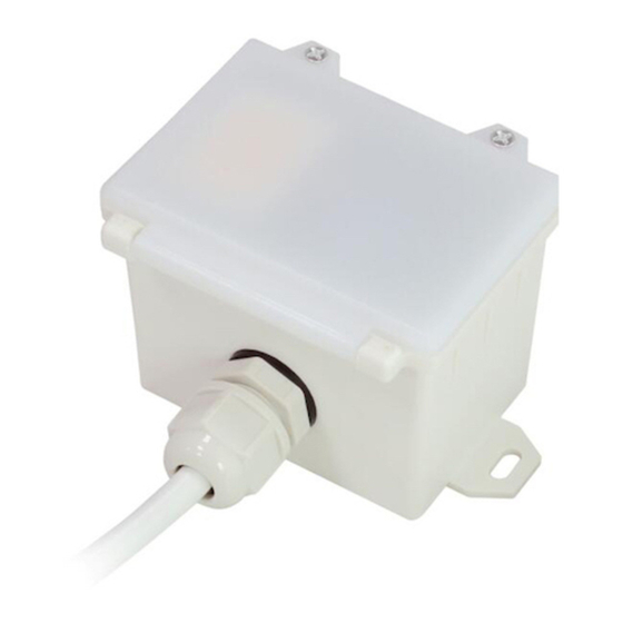
HIGH BAY MICROWAVE MOTION SENSOR
1. Technical Specifications
Product type
Tri-level control microwave motion sensor
Operating voltage
220~240VAC 50/60Hz
Capacitive: 800VA
Rated load
Resistive: 1000W
Power consumption
< 0.5W
o
Detection angle
360
Installation Height : 20m (forklift) 15m (person)
Detection area (max.)
Diameter (Ø) :20m
Detection range
10% / 50% / 75% / 100%
Hold time
2s / 30s / 1min / 5min / 10min / 15min / 20min / 30min
Stand-by time
0s / 10s / 1min / 5min / 10min / 30min / 1h / + ∞
Stand-by dimming level
10% / 20% / 30% / 50%
Daylight threshold
2 ~ 500Lux, Disable
Warmming up time
20s
o
o
Operating temperature
-20
C ~ +50
C
IP rating
IP65
3. Rotary Switch Settings
A rotary switch is built inside the sensor for
Rotary switch preset (Please
scene selection / fast programming. Total of
see the location in 2. Installation)
16 channels available:
Detection
Hold
Stand-by
Stand-by
Channel
range
time
time
dimming level
0
100%
5s
10s
10%
1
100%
1min
5min
10%
2
100%
5min
10min
10%
3
100%
5min
30min
10%
4
100%
5min
0s
Disable
5
100%
5min
+∞
10%
6
100%
5min
+∞
30%
7
100%
10min
10min
10%
8
100%
10min
30min
10%
9
100%
10min
+∞
10%
A
100%
10min
+∞
30%
B
75%
10min
+∞
10%
C
50%
10min
+∞
10%
D
100%
30min
+∞
10%
E
100%
30min
+∞
30%
F
100%
5s
10s
10%
Note: settings can also be changed by remote control HRC-11. The last action controls.
4. Functions
4.1 Tri-level Control (Corridor Function)
Hytronik builds this function inside the motion sensor to achieve tri-level control, for some areas it requires
a light change notice before switch-off.
It offers 3 levels of light: 100%-->dimmed light-->off; and 2 periods of selectable waiting time: motion
hold-time and stand-by period; Selectable daylight threshold and freedom of detection area.
4.2 Lux Off Function
The built-in daylight sensor can read ambient natural light and switch off the fixture automatically
whenever artificial light is unnecessary (natural light lux level exceeds daylight threshold).
Note: if the stand-by time is preset at "+∞", the fixture never switches off even when natural light
is sufficient.
Subject to change without notice.
2. Installation
Warnings:
1. Installation of the sensor involves connecting it to the mains supply. This work must be
carried out by a specialist in accordance with electrotechnical regulations.
2. Disconnect power supply before installing.
A. Ceiling mount
Rotary switch
LED indicator
Infrared receiver
Daylight sensor
Sensor module
Cable entry
Installation rack
B. Screw to the Luminaire by conduit
Rotary switch
LED indicator
Infrared receiver
Daylight sensor
Daylight
threshold
Cable entry
Disable
2Lux
10Lux
30Lux
Sensor module
10Lux
30Lux
Disable
2Lux
10Lux
30Lux
C. Attach to the shade by clamp
Disable
30Lux
10Lux
50Lux
Rotary switch
Disable
LED indicator
Infrared receiver
2Lux
Daylight sensor
Angle adjustment
Luminaire clamp
Sensor module
4.3 Load Indication
The light will flash ONCE rapidly after receiving the command from the remote controller.
Note: There is no load indication (the light will not flash) when button ON/OFF, POWER 100%
or POWER 80% is pressed.
5. Wiring Diagram
HMW31
4.1
66.6
81.5
6.
Detection Pattern
59.6
0.825"
66.6
89.9
7. Trouble Shooting
4.5
28.5
M
A
F L
N U
T C
O I
N
C
U A
E S
E R
M
E
Y D
59.6
66.6
163.2
The fixture does not light up
The fixture is always on
The fixture is on when it should not
HMW31-20230809-A2
Subject to change without notice.
L
N
Brown
Blue
Grey
Red
Black
HMW31
———This product should be installed by a qualified electrician.
0
10
10%
30%
50%
75%
20
(forklift)
Ceiling mounted detection pattern (m)
* For single person walking across, the detection range is reduced by 1/3.
C
U A
E S
Incorrect daylight threshold setting
Faulty fixture
No power supply
Detection zone not targeted
Continous movement in the detection zone
Sudden change in temperature due to weather (wind, rain, snow) or air
expelled from fans, open windows
L
LED driver
N
1-10V+
1-10V-
E R
M
E
Y D
Adjust daylight threshold setting
Replace fixture
Check power to sensor
Check detection area setting
Check detection area setting
Adjust zone, change installation site
HMW31-20230809-A2
Advertisement

Subscribe to Our Youtube Channel
Related Manuals for Hytronik HMW31


Summary of Contents for Hytronik HMW31
- Page 1 Continous movement in the detection zone Check detection area setting Hytronik builds this function inside the motion sensor to achieve tri-level control, for some areas it requires a light change notice before switch-off. Sudden change in temperature due to weather (wind, rain, snow) or air Adjust zone, change installation site It offers 3 levels of light: 100%-->dimmed light-->off;...
- Page 2 "Exp" refer to Expansion, these two buttons are reserved functions and pending future Exp 1 Exp 2 development. This key is not appliable on this product. Transmit This key is not appliable on this product. HF+PIR HF/PIR HMW31-20230809-A2 HMW31-20230809-A2 Subject to change without notice. Subject to change without notice.
Need help?
Do you have a question about the HMW31 and is the answer not in the manual?
Questions and answers