Hytronik HIR27 Manual
Flush mount pir motion sensor
Hide thumbs
Also See for HIR27:
- Quick start manual (9 pages) ,
- Installation and instruction manual (7 pages) ,
- Installation and instruction manual (2 pages)
Advertisement
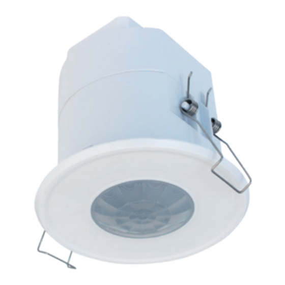
Flush Mount PIR Motion Sensor
HIR27
Independent DALI Occupancy Sensor with Daylight Harvest
Applications
Of ce, classroom and commercial interior spaces where DALI control is required in
small groups.
Of ce / Commercial Lighting
Classrooms
Stairwells / Corridors
HIR27 with DALI Broadcast Output
Designed with a low pro le for aesthetically demanding architectural projects whilst
retaining the functionality expected of the latest lighting controls. Control to the light
xtures is provided via self-powered DALI communication (up to 40 drivers).
Set-up of the sensor is carried out using a remote control handset with program memory
allowing one-key commissioning where common settings are used for multiple devices.
Features
DALI dimming control based upon occupancy (also known as corridor function).
Daylight harvest function to regulate light output for maintaining required lux level.
Store settings in the remote for easy commissioning when programming multiple sensors.
One-Key
Commissioning
Intelligent photocell - lights and sensors only operate when needed, natural light has proirity.
Intelligent
Photocell
TX
Synchronisation terminal for grouping of sensors.
synchronization
control
5-year warranty
Technical Data
Input Characteristics
Model No.
Operating voltage
220~240VAC 50/60Hz
Stand-by power
Switched power
Max. 40pcs devices, 80mA
Warming-up
Safety and EMC
EMC standard (EMC)
EN55015, EN61000, EN61547
EN60669-1, EN60669-2-1,
Safety standard (LVD)
AS/NES60669-1/-2-1
CB, CE , EMC, LVD, RCM
Certi cation
PIR
HIR27
<0.5W
Appr. 20s
ROHS compliance
Sensor Data
Model No.
Sensor principle
Detection range
Detection angle
Mounting height
Environment
Operation temperature
IP rating
IP20
HIR27
PIR detection
(O x H) 10m x 3m
O
360
5m (maximum)
O
O
Ta: -20
C ~ +50
C
IP20
Advertisement
Table of Contents

Related Manuals for Hytronik HIR27


Summary of Contents for Hytronik HIR27
- Page 1 Of ce / Commercial Lighting Classrooms Stairwells / Corridors HIR27 with DALI Broadcast Output Designed with a low pro le for aesthetically demanding architectural projects whilst retaining the functionality expected of the latest lighting controls. Control to the light xtures is provided via self-powered DALI communication (up to 40 drivers).
-
Page 2: Mechanical Structure
Mechanical Structure 65mm 70.5 75.2 1. Ceiling (drill hole 65mm) 2. Carefully prise off the cable clamps. 3. Make connections to the pluggable * Install blind as required terminal blocks. 4. Insert plug connectors and secure using the provided cable clamps, then clip terminal covers to the base. -
Page 3: Wire Preparation
Wiring Diagram LED Driver LED Driver LED Driver LED Driver Wire Preparation 0.75 - 2.5mm Pluggable screw terminal. It is recommended to make 7 - 8mm connections to the terminal before tting to the sensor. Detection Pattern Detection range with at lens Detection range with convex lens Radial movement up to 5m Radial movement up to 4m... -
Page 4: Functions And Features
Detection range with at lens Detection range with convex lens Detection range with convex lens and corridor blind B Detection range with at lens and corridor blind B Up to 8m Up to 7m Functions and Features Daylight Harvest Light will not switch on The light switches on The light turns on at full or dims to maintain the lux level. - Page 5 Synchronisation Function By connecting the “SYNC” terminals in parallel (see wiring diagram), no matter which sensor detects motion, all HIR27 in the group will turn on the lights when surrounding natural light is below the daylight threshold. The detection area could be widely enlarged in this way.
- Page 6 Scene program - 1-key commissioning 1. Press button “Start” to program. 2. Select the buttons in “Detection range”, “Daylight threshold”, “Hold-time”, “Stand-by time”, “Stand-by dimming level” to set all parameters. 3. Press button “Memory” to save all the settings programmed in the remote control. 4.
Need help?
Do you have a question about the HIR27 and is the answer not in the manual?
Questions and answers