
Related Manuals for Kontron KBox B-202-RPL


Summary of Contents for Kontron KBox B-202-RPL
- Page 1 USER GUIDE Abe mit Karlheiz gesporich und ich darf 2020 KBox B-202-RPL Doc. Preliminary User Guide, Rev 0.2 Doc. ID: 1073-0629 www.kontron.com // 1...
- Page 2 KBox B-202-RPL - Preliminary User Guide, Rev 0.2 This page has been intentionally left blank www.kontron.com // 2...
- Page 3 Kontron with respect to technical processes described in the user guide or any product characteristics set out in the user guide. Kontron assumes no responsibility or liability for the use of the described product(s), conveys no license or title under any patent, copyright or mask work rights to these products and makes no representations or warranties that these products are free from patent, copyright or mask work right infringement unless otherwise specified.
- Page 4 ENVIRONMENTAL DAMAGE (COLLECTIVELY, “HIGH RISK APPLICATIONS”). You understand and agree that your use of Kontron devices as a component in High Risk Applications is entirely at your risk. To minimize the risks associated with your products and applications, you should provide adequate design and operating safeguards.
- Page 5 If you have any difficulties using this user guide, discover an error, or just want to provide some feedback, contact Kontron Support. Detail any errors you find. We will correct the errors or problems as soon as possible and post the revised user guide on our website.
-
Page 6: Symbols
KBox B-202-RPL - Preliminary User Guide, Rev 0.2 Symbols The following symbols may be used in this user guide DANGER indicates a hazardous situation which, if not avoided, will result in death or serious injury. WARNING indicates a hazardous situation which, if not avoided, could result in death or serious injury. -
Page 7: For Your Safety
Therefore, in the interest of your own safety and of the correct operation of your new Kontron product, you are requested to conform with the following guidelines. -
Page 8: Lithium Battery Precautions
General Instructions on Usage In order to maintain Kontron’s product warranty, this product must not be altered or modified in any way. Changes or modifications to the product, that are not explicitly approved by Kontron and described in this user guide or received from Kontron Support as a special handling instruction, will void your warranty. -
Page 9: Table Of Contents
KBox B-202-RPL - Preliminary User Guide, Rev 0.2 Table of Contents Symbols ..........................................6 For Your Safety ........................................7 High Voltage Safety Instructions .................................. 7 Special Handling and Unpacking Instruction ............................7 Lithium Battery Precautions ..................................8 General Instructions on Usage ..................................8 Quality and Environmental Management .............................. - Page 10 KBox B-202-RPL - Preliminary User Guide, Rev 0.2 5.1.1. Overview ........................................32 5.2. Drive Bay ........................................33 5.3. Internal Expansion ....................................33 5.4. PCIe Slots ........................................34 5.5. Storage Bay (Smart Storage only) ..............................34 5.6. Reference Expansion Devices ................................35 Thermal Management ..................................
- Page 11 KBox B-202-RPL - Preliminary User Guide, Rev 0.2 11.1.1. Drive Bay RAID Configuration ................................64 11.1.2. Drive Bay RAID Software ................................... 65 11.2. Storage Bay RAID Array ..................................67 11.2.1. Storage Bay RAID Configuration ..............................67 11.3. Internal RAID Array ....................................68 11.3.1.
-
Page 12: List Of Tables
KBox B-202-RPL - Preliminary User Guide, Rev 0.2 List of Tables Table 1: Scope of Delivery ....................................21 Table 2: Accessories ......................................21 Table 3: Overview ......................................32 Table 4: Drive Bay Options ................................... 33 Table 5: Internal Expansion Options ................................. 33 Table 6: PCIe Expansion Card Slot Options ............................. - Page 13 Figure 35: 2.5” SSD dual RAID M.2 Module Settings ..........................64 Figure 36: Storage RAID (external) ................................67 Figure 37: Block Diagram of KBox B-202-RPL Smart Performance and Smart Storage ............69 Figure 38: Dimensions Front Panel ................................77 Figure 39: Dimensions Rear Panel ................................77 Figure 40: Dimensions Right Side ................................
-
Page 14: 1/ Introduction
2.5-inch SSD or two M.2 SSDs (RAID 1) to be integrated. With two GbE ports, of which one offers up to 2.5 GbE, and ten USB ports (including USB-C), the KBox B-202-RPL ensures high data throughput and connectivity. The product also features four DisplayPorts, a serial interface, and supports an input voltage of 230 VAC or 24 VDC. - Page 15 KBox B-202-RPL - Preliminary User Guide, Rev 0.2 System Memory 2x DIMM with DDR5 up to 64 GB Storage: 1x 2.5” SATA SSD (option) 1x SSD (M.2 2242 Key M, PCIe x4/NVME) (option) I/O Rear: ...
-
Page 16: 2/ General Safety Instructions
Only connect the product to an external power supply providing the voltage type (AC or DC) and the input power (max. current) specified on the Kontron Product Label and meeting the requirements of the Limited Power Source (LPS) and Power Source (PS2) of UL/IEC 62368-1 . -
Page 17: Instructions Générales De Sécurité
Le non-respect des consignes de sécurité générales suivantes peut entraîner des blessures pour l'utilisateur et/ou des dommages pour le produit. En cas de non-respect des consignes, Kontron Europe est exonéré de la responsabilité en cas d'accident, ceci s'applique également pendant la période de garantie. -
Page 18: Electrostatic Discharge (Esd) Precautions
KBox B-202-RPL - Preliminary User Guide, Rev 0.2 le produit présente des dommages visibles ou le produit ne fonctionne plus. Dans ce cas, le produit doit être éteint et il faut s'assurer que le produit ne puisse plus être utilisé. -
Page 19: Instructions For The Lithium Battery
The product is equipped with a CR2032 lithium battery and is not designed to operate without a lithium battery. If the lithium battery is empty or disconnected, the BIOS settings will be set to the factory defaults. Replace the Kontron specific lithium battery assembly only with the same type of lithium battery or with a Kontron recommended lithium battery type. - Page 20 KBox B-202-RPL - Preliminary User Guide, Rev 0.2 The product is not designed to operate without a lithium battery. If the lithium battery is empty or disconnected, the BIOS settings will be set to the factory defaults. www.kontron.com // 20...
-
Page 21: 3/ Shipment And Unpacking
KBox B-202-RPL - Preliminary User Guide, Rev 0.2 3/ Shipment and Unpacking 3.1. Packaging The KBox B-202-RPL is packaged together with all parts, in a product specific cardboard package designed to provide adequate protection and absorb shock. 3.2. Unpacking To unpack the KBox B-202-RPL, perform the following: Remove packaging. -
Page 22: Product Identification Type Label
KBox B-202-RPL - Preliminary User Guide, Rev 0.2 Part Number Part Part Description 1065 3430 Wall Mount Set Two wall mount brackets and four screws (M3x6) 0-0067-006 Chassis feet Four round adhesive rubber chassis feet 3.5. Product Identification Type Label The type label includes information product specific information such as the electrical specification and product compliance for the ordered configuration. -
Page 23: 4/ Product Features
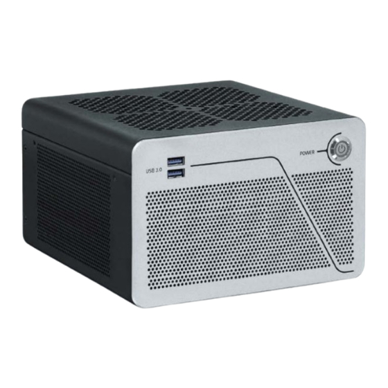
KBox B-202-RPL - Preliminary User Guide, Rev 0.2 4/ Product Features Before working with the KBox B-202-RPL, Kontron recommends that users take a few minutes to study this chapter and learn about the various parts and features. 4.1. Front Panel The front panel features the power button, two USB 3.2 Gen 1 ports, and ventilation openings for air-output. -
Page 24: Rear Panel
KBox B-202-RPL - Preliminary User Guide, Rev 0.2 4.2. Rear Panel The Smart Performance rear panel supports two PCIe expansion slots and three possible power connectors. Figure 4: Rear Panel (Smart Performance) 1x USB-C 3.2 1x Kensington lock 17 PCIe slot 1 (populated with single card) 3x USB 3.2 Gen 2... -
Page 25: Figure 5: Rear Panel (Smart Storage)
KBox B-202-RPL - Preliminary User Guide, Rev 0.2 The Smart Storage rear panel supports a dual storage bay or AC Power connector, and one PCIe expansion slot. Figure 5: Rear Panel (Smart Storage) 1x USB-C 3.2 1x Serial port 15 1x DC IN (3-pins, mating connector supplied, connects to 24 VDC) 3x USB 3.2 Gen 2... -
Page 26: Usb 3.2 Gen 2/Gen1 Ports
The two USB 3.2 Gen 2/Gen 1 Type-A are backward compatible enabling the connection of USB 3.0 or USB 2.0 devices. Kontron recommends the use of USB 3.2 Gen 2 compliant devices and cables only. The use of devices and cables that violate the USB 3.2 Gen 2 specification may cause non-recognition of the device or read/write errors. -
Page 27: Lan Ports
The Wi-Fi option populates the 2230 key E socket. When installed this socket is not available for other M.2 modules. 4.2.9. GPIO (option) The GPIO port option is available on the Smart Performance variant only. For more information, contact your Kontron sales representative. www.kontron.com // 27... -
Page 28: Dc In (Default)
KBox B-202-RPL - Preliminary User Guide, Rev 0.2 4.2.10. DC IN (default) The DC IN power jack (Figure 4 & Figure 5, pos. 12) connects to the supplied external AC/DC (90/264 VAC to 12 VDC, 150 W) power supply. For more information, see Chapter 12.4.1: AC/DC (150 W) Power Supply and for the pin assignment, see Chapter 13.1: DC IN 12 VDC, Power Jack (default). -
Page 29: Ac-In (Option-Smart Storage Line Only)
KBox B-202-RPL - Preliminary User Guide, Rev 0.2 4.2.13. AC-IN (option-Smart Storage line only) The optional 3-pin AC-IN connector (Figure 4 pos. 21) connects directly to the main power supply for your region using the supplied power cable. The AC-IN connector is available with the Smart Storage line only. -
Page 30: Left And Right Side
KBox B-202-RPL - Preliminary User Guide, Rev 0.2 4.3. Left and Right Side The sides feature ventilation openings for air-output. The ventilation openings on the right side are contained within a removable expansion door that enables access to the PCIe slot for easy installation of PCIe expansion cards. For more information regarding supported PCIe expansion cards, see Chapter 5.5: PCIe Slot. -
Page 31: Top Cover And Bottom Side
KBox B-202-RPL - Preliminary User Guide, Rev 0.2 4.4. Top Cover and Bottom Side The top cover features ventilation openings, a metal mesh and a metal plate with a circular opening. The circular opening’s position above the internal fan aids ventilation and the metal mesh prevents unwanted items from entering the product. -
Page 32: 5/ System Expansion
KBox B-202-RPL - Preliminary User Guide, Rev 0.2 5/ System Expansion 5.1. Before Expanding Before expanding the KBox B-202-RPL, users must consider the product’s maximum allowed power consumption and take cooling into consideration. 5.1.1. Overview Table 3: Overview Smart Performance... -
Page 33: Drive Bay
KBox B-202-RPL - Preliminary User Guide, Rev 0.2 5.2. Drive Bay The Smart Performance line and Smart Storage line both include an external drive bay. The external drive bay supports one removable 2.5” SSD drive or 2.5” SSD dual M.2 RAID (RAID 0/1) module. -
Page 34: Pcie Slots
KBox B-202-RPL - Preliminary User Guide, Rev 0.2 5.4. PCIe Slots The Smart Performance line supports the installation of two single or one dual slot PCIe expansion card(s). The Smart Storage line supports the installation of one single slot PCIe expansion card. -
Page 35: Reference Expansion Devices
1x 3.5“ SATA HDD Factory installed internal drive SATA III 6 Gb/s. 5.6. Reference Expansion Devices For a list of the KBox B-202-RPL Smart Performance line and Smart Storage line reference expansion devices, visit Kontron’s Customer Section www.kontron.com // 35... -
Page 36: 6/ Thermal Management
6/ Thermal Management 6.1. Active Cooling The KBox B-202-RPL is actively fan cooled. An internal processor fan draws in air through the top cover’s ventilation openings and distributes the incoming air over critical internal components before the air exits the through the ventilation openings on the right, left, front and rear sides. -
Page 37: Mount Orientation
KBox B-202-RPL - Preliminary User Guide, Rev 0.2 6.2. Mount Orientation The permitted mounting orientations are horizontal with the top side facing upward and vertical in all mount orientations. Mounting the product with the top cover facing downwards is not permitted. If the top cover faces downwards, not enough air enters the product to cool the processor adequately. -
Page 38: 7/ Assembly
7/ Assembly 7.1. Before Assembling Before opening the KBox B-202-RPL to access internal components, observe the safety instructions within this chapter and the safety instructions in Chapter 2/General Safety Instructions. For third party products, consult the documentation provided by the components manufacturer. Kontron recommends expanding the product, before installation. -
Page 39: Installing And Removing An M.2 Module
KBox B-202-RPL - Preliminary User Guide, Rev 0.2 Remove the two top cover screws on the rear panel and retain the screws for later use. Lift the top cover a few centimeters at the rear of the chassis and pull the top cover gently away from the front panel to release the top cover from the front-panel-holding-brackets. -
Page 40: Opening The Drive Bay
KBox B-202-RPL - Preliminary User Guide, Rev 0.2 Insert the M.2 module into the M.2 socket gently and at an angle, until the fixing hole on the M.2 module aligns with the corresponding motherboard’s nut. Secure the M.2 module by pressing down on the free end, and carefully fixing with a screw to the corresponding nut on the motherboard, until flat with the motherboard. -
Page 41: Installing And Removing 2.5" Ssd Drive
KBox B-202-RPL - Preliminary User Guide, Rev 0.2 Release the drive bay cover’s screw using a torx (08 x 60) screwdriver. Lift up the drive bay cover a few centimeters to release the internal device from the holding-plate on the drive bay cover’s rear side. -
Page 42: Installing And Removing 2.5" Ssd Dual M.2 Raid Module
KBox B-202-RPL - Preliminary User Guide, Rev 0.2 To install a 2.5” SSD in the drive bay, perform the following: Close all applications. Shut down the product properly using the power button and disconnect the power cable from the power source. Disconnect all peripherals Open the drive bay cover, as described in Chapter 7.3: Opening the Drive Bay, steps 1 to 6. -
Page 43: Figure 15: 2.5" Ssd Dual Raid M.2 Module
KBox B-202-RPL - Preliminary User Guide, Rev 0.2 Figure 15: 2.5” SSD Dual RAID M.2 Module Jumper switches Reset switch (do not press!) 2x screws for M.2 SSD module 4x Foam buffer M.2 socket 2 M.2 socket 1 SATA power connector SATA data connector Figure 16: Drive Bay with 2.5”... - Page 44 KBox B-202-RPL - Preliminary User Guide, Rev 0.2 If the 2.5” SSD dual M.2 RAID module’s RAID array is not configured or the configuration must be changed, see Chapter 11.1: Drive Bay RAID, to set the RAID array and then proceed with step 7.
-
Page 45: Connecting The Wi-Fi Antenna (Option)
KBox B-202-RPL - Preliminary User Guide, Rev 0.2 Kontron recommends replacing a faulty drive with a drive of the same capacity and type as the mirrored drive. When different capacity drives are used, the working capacity is only as large as the smallest drive’s capacity. -
Page 46: Installing And Removing Pcie Expansion Cards
KBox B-202-RPL - Preliminary User Guide, Rev 0.2 Move the expansion door outwards at the free end and slide towards the rear of the chassis to release the door’s holding plate. Close the expansion door, by proceeding in the reverse order (steps 4 to 3). -
Page 47: Storage Bay
KBox B-202-RPL - Preliminary User Guide, Rev 0.2 Secure the expansion door by positioning the holding plate in the inside of the chassis. Push the door until the two screw holes align with the screw holes on the chassis. Close and secure the door with the screws retained in step 1 , as described in Chapter 7.5: Opening the Expansion Door. -
Page 48: Figure 19: Storage Bay Tray
KBox B-202-RPL - Preliminary User Guide, Rev 0.2 Figure 19: Storage Bay Tray 2.5” SSD Tray Tray arm Fixing screws (min. two) To install a 2.5” Removable SSD, perform the following: Unlock the storage bay using the key supplied. Press the tab on the left side of the tray arm towards the left and the arm swings open. -
Page 49: 8/ Installation
8/ Installation 8.1. Before Installing Before installing the KBox B-202-RPL in the operating environment, ensure that the operating environment meets the specification stated within this user guide, and that there is sufficient access to the product’s power connector, the front and rear panel I/O connectors and the installed PCIe cards. -
Page 50: Chassis Feet
KBox B-202-RPL - Preliminary User Guide, Rev 0.2 Ensure the product’s weight can be supported by mounting on a flat, solid surface using suitable screws. Support I/O cables and power cables to minimize the strain on the product’s connectors. Ensure there is clearance for users to •... -
Page 51: Mounting Brackets (Option)
KBox B-202-RPL - Preliminary User Guide, Rev 0.2 8.3. Mounting Brackets (option) To mount on a surface vertically, horizontally, underneath or topside use the mounting brackets. Figure 21: Mounting Bracket Mounting holes (10 mm clearance) Key mounting holes for mount surface Mounting holes (no clearance) Each mounting bracket contains two sets of mounting holes. -
Page 52: Mounting Brackets Desktop
KBox B-202-RPL - Preliminary User Guide, Rev 0.2 Use the mounting bracket’s key mounting holes (Figure 21, pos. 3), to mount on the mounting surface (wall or desktop) while observing the specified clearance of 10 mm (keep out area) as indicated in Figure 22 and Figure 23. -
Page 53: Figure 24: Mounting Brackets On A Desktop/Mount Surface
KBox B-202-RPL - Preliminary User Guide, Rev 0.2 To mount the product underneath a desktop/mount surface, use the Wall Mount Set, see Table 2: Accessories. Use the upper pair of mounting holes on the left and right sides of the chassis (Figure 6, Pos. 4) and the mounting holes on the bracket (Figure 21, Pos. -
Page 54: Mounting On A Wall
KBox B-202-RPL - Preliminary User Guide, Rev 0.2 8.3.2. Mounting on a Wall To mount the product on a wall use the Wall Mount Set, see Table 2: Accessories. With the top cover facing outwards, use the lower pair of mounting holes on the left and right sides of the chassis (Figure 6, pos. 3) and use the mounting bracket holes (Figure 21, pos. -
Page 55: 9/ Starting Up
9/ Starting Up 9.1. Before Starting Before connecting the KBox B-202-RPL to power, read the instructions in this user guide and observe the safety instructions in Chapter 2/General Safety Instructions. The product comes hardware configured, and on request with a pre-installed Operating System (OS) and all the necessary drivers (in accordance with the ordered hardware configuration);... -
Page 56: Connecting The External Ac/Dc (150 W) Power Supply
Only connect the product to the supplied external power supply providing the voltage type (AC or DC) and the input power (max. current) specified on the Kontron Product Label and meeting the requirements of the Limited Power Source (LPS) and Power Source (PS2) of UL/IEC 62368-1. -
Page 57: Connecting The Ac/Dc (240 W) Power Supply (Option)
Only connect the product to the supplied external power supply providing the voltage type (AC or DC) and the input power (max. current) specified on the Kontron Product Label and meeting the requirements of the Limited Power Source (LPS) and Power Source (PS2) of UL/IEC 62368-1. -
Page 58: Connecting To A 24 Vdc Power Supply (Option)
KBox B-202-RPL - Preliminary User Guide, Rev 0.2 9.4. Connecting to a 24 VDC Power Supply (option) The supplied 3-pin mating power connector (PSC 1.5/ 3-F) connects to the optional DC IN 3-pin power connector. The user is responsible for wiring the product correctly to the external24 VDC power supply by marking the wires clearly with (+/-) to ensure the correct connection to the DC IN 3-pin power connector. -
Page 59: Connecting To A Dc Power Supply
KBox B-202-RPL - Preliminary User Guide, Rev 0.2 The wiring is not part of the delivery and must be provided by the user. • Use copper wire only if the field wiring terminal is for copper wire connection only •... -
Page 60: Switching On/Off
Pay attention to the manufacturer’s OS specifications for integrated hardware components. For supported software information, see Table 19: Software Specification. To download relevant drivers for hardware components visit Kontron’s Customer Section Pay attention to the manufacturer OS specifications relating to integrated hardware components. -
Page 61: 10/ Bios
BIOS The KBox B-202-RPL uses the AMI Aptio 5.x (UEFI) BIOS supported by the motherboard. This chapter informs users how to start the BIOS, use the BIOS setup to configure, and perform a BIOS update. Note that BIOS features are open to change and may not be available in the latest version of the motherboard’s BIOS. -
Page 62: Bios Navigation
<RETURN> key executes a command or selects a submenu 10.4. BIOS Update To ensure compatibility with new OS, hardware, software or to integrate new BIOS functions Kontron recommends regular BIOS updates. Additionally, if a problem cannot be solved using a new driver, Kontron recommends updating the BIOS. 10.4.1. -
Page 63: Recover Bios
To recover BIOS perform the following: Close all applications. Shut down the product properly and disconnect the power cable from the power source. Copy the BIOS ZIP package content (K3833-Q1.ROM file) in Kontron’s Customer Section to a FAT32 formatted USB stick. -
Page 64: 11/ Raid
KBox B-202-RPL - Preliminary User Guide, Rev 0.2 11/ RAID The KBox B-202-RPL supports the following RAID Array options: Drive bay RAID Array (Smart Performance and Smart Storage) Storage bay RAID Array (Smart Storage only) Internal RAID Array (Smart Storage only) 11.1. -
Page 65: Drive Bay Raid Software
KBox B-202-RPL - Preliminary User Guide, Rev 0.2 Table 10: RAID Module Jumper Settings RAID Array Type J1 Setting J2 Setting RAID 0 RAID 1 To configure the RAID array the 2.5” SSD dual M.2 RAID module must be powered on using either the product’s drive bay (refer to step 6) or an external SATA adapter from a SATA source (refer to step 7). -
Page 66: Table 11: S.m.a.r.t. Information Memory Attributes Examples
KBox B-202-RPL - Preliminary User Guide, Rev 0.2 The S.M.A.R.T health check helps predict memory failures by counting how often memory-attribute problems occur, see Table 11: S.M.A.R.T. Information Memory Attributes. Table 11: S.M.A.R.T. Information Memory Attributes Examples Memory-attributes Later bad... -
Page 67: Storage Bay Raid Array
KBox B-202-RPL - Preliminary User Guide, Rev 0.2 11.2. Storage Bay RAID Array The storage bay RAID array is factory installed as RAID 1 by default. Table 14: Storage Bay RAID Array RAID Quantity Interface Position RAID Type RAID Monitoring Drive type 2.5”... -
Page 68: Internal Raid Array
KBox B-202-RPL - Preliminary User Guide, Rev 0.2 11.3. Internal RAID Array The internal RAID array uses two 2.5” SSDs, factory installed in an internal storage cage. Internal RAID is only available for the Smart Storage line. Table 15: Internal RAID... -
Page 69: 12/ Product Specification
KBox B-202-RPL - Preliminary User Guide, Rev 0.2 Product Specification 12.1. Block Diagrams Figure 37: Block Diagram of KBox B-202-RPL Smart Performance and Smart Storage KBox B-202-RPL Smart Performance Dual Channel 4x DisplayPort DDR5-4800 SODIMM (up to 64 GB) 1x LAN (1 GbE) 1x LAN (2.5 GbE) - Page 70 KBox B-202-RPL - Preliminary User Guide, Rev 0.2 KBox B-202-RPL Smart Storage Dual Channel DDR5-4800 4x DisplayPort SODIMM (up to 64 GB) System Fan 1x LAN (1 GbE) Fan Connector 1x LAN (2.5 GbE) 1x PCIe x8 PCIe slot 13th Gen.
-
Page 71: Hardware Specification
KBox B-202-RPL - Preliminary User Guide, Rev 0.2 12.2. Hardware Specification Table 16: Hardware Specification Product KBox B-201-RPL Motherboard Type K3833-Q mini-ITX Processors Intel® 13 Gen Core™ processors and Pentium® Gold processor Processors Cores Base Freq. Turbo Freq. Base Power i9-13900E 1.8 Ghz... -
Page 72: Table 17: Storage Specification
KBox B-202-RPL - Preliminary User Guide, Rev 0.2 Table 17: Storage Specification Smart Storage Smart Performance Drive Bay (removable) Type 2.5” SSD Drive Quantity Capacity 512 GB, 1 TB, 2 TB Interface SATA III, 6Gb/s Installed Removable Smart Storage Smart Performance... -
Page 73: Software Specification
KBox B-202-RPL - Preliminary User Guide, Rev 0.2 Table 18: External Expansion Slots Smart Storage Smart Performance Quantity & Type 1x PCIe x16 or 1x PCIe x16 2x PCIe x8 Size full height, half-length PCIe 2x PCIe x8 Interface PCIe Gen 3... -
Page 74: Ac/Dc (240 W) Power Supply (Option)
Power Rating 150 W Only connect the product to the external AC/DC power supply supplied by Kontron and providing the voltage type (AC or DC) and the input power (max. current) specified on the Kontron Product Label and meeting the requirements of the Limited Power Source (LPS) and Power Source (PS2) of UL/IEC 62368-1. -
Page 75: Ac-In (Option)
12.4.5. Power Protection The power source supplied by Kontron incorporates protection and supply features such as over current, over temperature, over voltage and brownout protection, to protect the product against fluctuations and interruptions in the delivered mains power supply and help to ensure operation without loss of data or damage to the product. -
Page 76: Power Consumption
The minimum off state time, to allow internal voltages to discharge, depends on the power supply used and additional electrical factors. To determine the required off state time, each case must be considered individually. For more information, contact Kontron Support. 12.4.6. -
Page 77: Environmental Specification
KBox B-202-RPL - Preliminary User Guide, Rev 0.2 12.5. Environmental Specification Table 26: Environmental Specification Temperature (Operating) 0°C to 45°C (32°F to 113°F) (Non-Operating) -20°C to +80°C (-4°F to 176°F) Relative (Operating) 93% RH @ 40°C, non-condensing Humidity (Non-Operating) 93% RH @ 40°C, non-condensing Altitude (Operating) 5000 m (16400 ft.) Max. -
Page 78: Figure 40: Dimensions Right Side
8.8 mm 201 mm Figure 42: Dimension Top Cover Figure 43: Dimensions Bottom Side 130 mm 190 mm For the products 3D STEP data, visit Kontron’s Customer section and select the product KBoxB> KBox B-202-RPL> KBox B-202-RPL Documentation www.kontron.com // 78... -
Page 79: Figure 44: Dimensions With Mounting Brackets
KBox B-202-RPL - Preliminary User Guide, Rev 0.2 Figure 44: Dimensions with Mounting Brackets 230 mm 190 mm 10.5 mm Ø 8.5 250 mm For the products 3D STEP data, visit Kontron’s Customer section and select the product KBoxB> KBox B-202-RPL> KBox B-202-RPL Documentation www.kontron.com // 79... -
Page 80: Compliance
KBox B-202-RPL - Preliminary User Guide, Rev 0.2 12.7. Compliance The KBox B-202-RPL plans to comply with the relevant requirements and the approximation of the laws relating to the CE Mark for non-Wi-Fi variants and CE Radio Equipment Directive (RED) for Wi-Fi variants, and the standards that are constitutional parts of the declaration. -
Page 81: Table 29: International Compliance
Safety Assessment of electronic and electrical equipment related to human exposure restrictions for electromagnetic fields (0 Hz - 300 GHz) The KBox B-202-RPL plans to comply with the following country specific certifications. Table 29: International Compliance USA/CANADA FCC 47 CFR Part 15 (Class B) and ICES-003 Complies with part 15 FCC rules and regulations of title 47 of the CFR rules for class B products;... - Page 82 KBox B-202-RPL - Preliminary User Guide, Rev 0.2 Use shielded I/O cables when connecting to peripheral devices. Failure to do so may violate FCC/ICES rules. All tests were performed with supplied external AC/DC power supply. Failure to use the supplied power supply may invalidate the FCC compliance & class.
-
Page 83: 13/ Connectors And Leds
KBox B-202-RPL - Preliminary User Guide, Rev 0.2 Connectors and LEDs Low-active signals are indicated by a minus sign. 13.1. DC IN 12 VDC, Power Connector (default) The supplied external AC/DC, 150 W power supply connects to the DC IN power jack. -
Page 84: Dc In 24 Vdc (Option)
Only connect the product to an external 24 VDC power supply providing the input power (max. current) specified on the Kontron Product Label and meeting the requirements of the Limited Power Source (LPS) and Power Source (PS2) of UL/IEC 62368-1. -
Page 85: Usb 3.2 Gen2/Gen1 Port Pin Assignment
KBox B-202-RPL - Preliminary User Guide, Rev 0.2 13.5. USB 3.2 Gen2/Gen1 Port Pin Assignment All USB3 connectors provide separate signal lines for USB3.2 and USB2.0. Table 33: USB 3.1 Gen 2/1 /Type-A) Pin Assignment Signal Name Signal Name 9-pin USB 3.2 (Type A) Port... -
Page 86: Display Port (Dp) V1.4A Pin Assignment
KBox B-202-RPL - Preliminary User Guide, Rev 0.2 13.8. Display Port (DP) V1.4a Pin Assignment Table 36: Display Port (DP) Connector Pin Assignment Signal Name Signal Name DP V1.4 Connector Link0+ Link0- Link1+ Link1- Link2+ Link2- Link3+ Link3- DVI dongle detect... -
Page 87: Com1 Port (Rs232) Pin Assignment
KBox B-202-RPL - Preliminary User Guide, Rev 0.2 13.10. COM1 Port (RS232) Pin Assignment Table 38: Serial Interface COM port (RS232) Connector Pin Assignment RS232 RS232 D89 Connector 13.11. Audio Line-out and Line-in Connector Pin Assignment Table 39: Audio Line-OUT Audio Line-IN Pin Assignment... -
Page 88: Jumpers
Figure 45: Recover BIOS Jumper Default jumper setting Recover position (orange) Table 40: Recover BIOS Jumper Pins State 24-pin Front Panel Header 20-22 Default 22-24 Recover BIOS Default Recover BIOS For further motherboard information, visit Kontron’s K3833-Q mITX motherboard website. www.kontron.com // 88... -
Page 89: 14/ Maintenance
ATTENTION: Risque d’explosion si la batterie est remplacée par un type incorrect. Mettre au rebus les batteries usagées selon les instructions. The CR2032 lithium battery must be replaced with an identical 3 Volt lithium battery or a Kontron recommended lithium battery. To replace the on-board Lithium battery, perform the following: Close all applications. - Page 90 KBox B-202-RPL - Preliminary User Guide, Rev 0.2 Insert the lithium battery into the battery holder. Ensure correct polarity with the PLUS side of the battery facing towards the metal clamp, as shown by the + and – symbols in Figure 46.
-
Page 91: 15/ Storage And Transportation
The storage facility must meet the products environmental storage requirements as stated within this user guide. Kontron recommends keeping the original packaging material for future storage or warranty shipments. -
Page 92: 16/ Technical Support
RMA number. The buyer accepts responsibility for all freight charges for the return of goods to Kontron's designated facility. Kontron will pay the return freight charges back to the buyer's location in the event that the equipment is repaired or replaced within the stipulated warranty period. -
Page 93: Warranty
Limitation/Exemption from Warranty Obligation In general, Kontron shall not be required to honor the warranty, even during the warranty period, and shall be exempted from the statutory accident liability obligations in the event of damage caused to the product due to failure to observe the following: ... -
Page 94: List Of Acronyms
KBox B-202-RPL - Preliminary User Guide, Rev 0.2 List of Acronyms Table 41: List of Acronyms BIOS Basic Input Output System Operating System BlueTooth Power Supply Unit Code of Federal Regulations RAID Redundant Array of Independent Disks Communication port REACH... -
Page 95: About Kontron
KBox B-202-RPL – Preliminary User Guide, Rev 0.2 About Kontron Kontron is a global leader in IoT/Embedded Computing Technology (ECT). Kontron offers individual solutions in the areas of Internet of Things (IoT) and Industry 4.0 through a combined portfolio of hardware, software and services. With its standard and customized products based on highly reliable state-of-the-art technologies, Kontron provides secure and innovative applications for a wide variety of industries.
Need help?
Do you have a question about the KBox B-202-RPL and is the answer not in the manual?
Questions and answers