Table of Contents
Advertisement
Quick Links
Advertisement
Table of Contents

Related Manuals for Kontron KBox B-201


Summary of Contents for Kontron KBox B-201
- Page 1 USER GUIDE KBox B-201 Doc. Rev. 1.0 Doc. ID: 1062-7377 www.kontron.com // 1...
- Page 2 KBox B-201 - Rev. 1.0 This page has been intentionally left blank www.kontron.com // 2...
- Page 3 In cases of doubt, please contact Kontron. This user guide is protected by copyright. All rights are reserved by Kontron. No part of this document may be reproduced, transmitted, transcribed, stored in a retrieval system, or translated into any language or computer language, in any form or by any means (electronic, mechanical, photocopying, recording, or otherwise), without the express written permission of Kontron.
- Page 4 ENVIRONMENTAL DAMAGE (COLLECTIVELY, "HIGH RISK APPLICATIONS"). You understand and agree that your use of Kontron devices as a component in High Risk Applications is entirely at your risk. To minimize the risks associated with your products and applications, you should provide adequate design and operating safeguards.
- Page 5 If you have any difficulties using this user guide, discover an error, or just want to provide some feedback, contact Kontron support. Detail any errors you find. We will correct the errors or problems as soon as possible and post the revised user guide on our website.
-
Page 6: Symbols
KBox B-201 - Rev. 1.0 Symbols The following symbols may be used in this user guide DANGER indicates a hazardous situation which, if not avoided, will result in death or serious injury. WARNING indicates a hazardous situation which, if not avoided, could result in death or serious injury. -
Page 7: For Your Safety
Therefore, in the interest of your own safety and of the correct operation of your new Kontron product, you are requested to conform with the following guidelines. -
Page 8: Lithium Battery Precautions
General Instructions on Usage In order to maintain Kontron’s product warranty, this product must not be altered or modified in any way. Changes or modifications to the product, that are not explicitly approved by Kontron and described in this user guide or received from Kontron Support as a special handling instruction, will void your warranty. -
Page 9: Table Of Contents
KBox B-201 - Rev. 1.0 Table of Contents Symbols ..........................................6 For Your Safety ........................................7 High Voltage Safety Instructions .................................. 7 Special Handling and Unpacking Instruction ............................7 Lithium Battery Precautions ..................................8 General Instructions on Usage ..................................8 Quality and Environmental Management .............................. - Page 10 11.1. Block Diagram- KBox B-201 ................................. 45 11.2. Technical Specification ..................................46 11.3. Mechanical Specification ..................................48 11.3.1. Dimension Diagrams – KBox B-201 ............................... 48 11.3.2. Dimension Diagrams- Wall Mount Brackets ..........................50 11.4. Environmental Specification ................................51 11.5. CE-Directives, Standards and Approvals ............................51 11.6.
-
Page 11: List Of Tables
List of Figures Figure 1: KBox B-201 ......................................17 Figure 2: Type Label ......................................18 Figure 3: KBox B-201 Overview ..................................19 Figure 4: Front View ......................................20 Figure 5: Rear View ......................................21 Figure 6: Left Side and Right Side Views ..............................23 Figure 7: Top View ...................................... - Page 12 Figure 28: Inserting the Band ..................................40 Figure 29: Positioning the PSU ..................................40 Figure 30: KBox B-201 and PSU Mounting Position ..........................40 Figure 31: Non VESA Stand Monitor Assembly ............................41 Figure 32: Installed VESA 100 Mount Assembly – non VESA Stand Monitor ................41 Figure 33: VESA Monitor Stand Assembly ...............................
-
Page 13: 1/ General Safety Instructions For It Equipment
Kontron is exempt from accident liability, this also applies during the warranty period. The product has been built and tested according to the basic safety requirements for low voltage (LVD) applications and has left the manufacturer in safety-related, flawless condition. - Page 14 KBox B-201 - Rev. 1.0 Additional safety instructions for DC power supply circuits To guarantee safe operation of devices with DC power supply voltages larger than 60 volts DC or a power consumption larger than 120 VA, please observe that: ...
- Page 15 KBox B-201 - Rev. 1.0 1.2. Instructions for the Lithium Battery The KBox B-201’s mainboard is equipped with a lithium battery. When replacing the battery please observe the instructions described in Chapter 15.3.1: Replacing Lithium Battery. Danger of explosion when replacing with wrong type of battery. Replace only with the same or equivalent type recommended by the manufacturer.
-
Page 16: 2/ Electromagnetic Compatibility (Class B Device)
Consult the dealer or an experienced radio/TV technician for help. Kontron Europe GmbH is not responsible for any radio television interference caused by unauthorized modifications of this equipment or the substitution or attachment of connecting cables and equipment other than those specified by Kontron Europe GmbH. -
Page 17: 3/ Introduction
The KBox B-201 is part of Kontron’s Box PC family designed for high performance needs in a small form factor. Based on the Intel® embedded 6th and 7th generation platforms with mini ITX mainboard, the KBox B-201 features high processing capability and long-term availability. -
Page 18: 4/ Scope Of Delivery
4x spacer used to mount the KBox B-201 and PSU on the back of a VESA 100 monitor 4.1. Packaging The KBox B-201 is packaged together with all standard parts listed in Table 1: Scope of Delivery, in a product specific cardboard package designed to provide adequate protection to according the EN 60068-2-31 and absorb shock. -
Page 19: 5/ Product Overview
KBox B-201 - Rev. 1.0 5/ Product Overview Before working with the KBox B-201, Kontron recommends that users take a few minutes to learn about the various parts of the KBox B-201. The following chapter provides information regarding KBox B-201 features The KBox B-201 is a small form factor Box PC family designed for high performance needs with 6 Gen. -
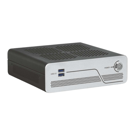
Page 20: Front View
5.1.1.1. Power-On Button The power-on button powers the KBox B-201 on and off. The power-on button includes an integrated power LED that lights up blue to indicate the powered on state. By pressing the power-on button for longer than four seconds a forced system shutdown will be initiated, before the power to the system is turned off. -
Page 21: Rear View
KBox B-201 - Rev. 1.0 5.2. Rear View The rear panel contains the main I/O interfaces and includes the power in connector (DC IN), ventilation holes for air- output, and two fastening screws for the top cover. Figure 5: Rear View... - Page 22 To avoid disturbances, it is recommended not to use any adapters such as DP/VGA, DP/DVI or DP/HDMI adapter at the DisplayPort connectors. The KBox B-201 supports up to three independent digital displays (2x DP + 1x DVI-D) 5.2.1.5. Serial Ports The RS232 serial port 9-pin D_SUB connector enables the connection of a serial device to the system.
-
Page 23: Left And Right Side Views
KBox B-201 - Rev. 1.0 5.3. Left and Right Side Views The right and left sides of the chassis contain ventilation holes for air-output. The threaded screw holes (Figure 6, pos. 2) are used to attach mounting brackets (see Chapter 9.3: Mounting Brackets (Option)) or to attach a vertical stand (see Chapter 9.2: Vertical Stand (Option)). -
Page 24: Top Cover And Bottom Views
The bottom side contains an external 2.5” SSD drive bay that is opened or closed by a single screw. Additionally, four threaded holes enable the KBox B-201 to be mounted on the back of a VESA 100 compatible monitor using Kontron’s VESA 100 mount assembly, see Chapter 9.4: VESA 100 Mount Assembly (Option). -
Page 25: 6/ System Extension
KBox B-201 - Rev. 1.0 6/ System Extension 6.1. External Storage 6.1.1. 2.5” SSD Drive Bay The external 2.5” SSD drive bay uses the SATA interface (SATA III / SATA-600 compliant) for 2.5” SSD memory expansion. 6.2. Internal Expansion It is possible to install a fullsize/halfsize mSATA or mPCIe expansion card in a shared socket, and an M.2 (2242/2262) expansion card. -
Page 26: 7/ Accessing Internal Components
Operate the KBox B-201 only in the closed condition. It is only ensured that users do not have access to the KBox B-201’s internal components during operation when the top cover is properly installed and secured with two fastening screws (Figure 5 pos. -
Page 27: Figure 9: Top Cover Fastening Screws
Close all applications. Shut down the system properly and disconnect the power cord from the power source. Disconnect all peripherals. Place the KBox B-201 on a flat, clean and ESD-safe surface. Remove the two top cover screws on the rear panel, see Figure 9: Top Cover Fastening Screws, and retain the screws to close the top cover later. -
Page 28: Opening And Closing Ssd Drive Bay Cover
Disconnect all peripherals. Place the KBox B-201 on a flat, clean and ESD-safe surface with the bottom side facing upwards. Use a torx screwdriver (08 x 60) to remove the screw holding the SSD drive bay cover, see Figure 8: Bottom View (pos. -
Page 29: Installing And Removing External 2.5" Ssd
KBox B-201 - Rev. 1.0 7.2.1. Installing and Removing External 2.5” SSD To install a 2.5” SSD, perform the following steps: Open the SDD drive bay cover by following the instructions in Chapter 7.2: Opening and Closing SSD Drive Bay Cover (steps 1-6). -
Page 30: Installing And Removing Internal M.2 Ssd Card
KBox B-201 - Rev. 1.0 7.3. Installing and Removing Internal M.2 SSD Card To install an M.2 card follow the steps below: Close all applications; shut down the system properly and disconnect the connection to the power source. Disconnect all peripherals Open the chassis as described in Chapter 7.1: Opening and Closing the Chassis (steps 1-6). -
Page 31: Installing And Removing Internal Mpcie Expansion Card
KBox B-201 - Rev. 1.0 After installing or removing a mSATA SSD the partitioning of the memory maybe different. To remove a mSATA expansion card from the shared mSATA/mPCIE socket, follow the steps below: Close all applications, shut down the system properly, and disconnect the connection to the power source. -
Page 32: 8/ Thermal Considerations
8.1. Active Cooling The KBox B-201 is an active fan cooled system. Air enters through the top cover’s ventilation holes, see Figure 14: Air- intake Ventilation Holes and is distributed by the fan over the mainboard before being extracted by ventilation holes on the right and left sides and at the rear, see Figure 15: Air-output Ventilation Hole. -
Page 33: 9/ Installation Instructions
The KBox B-201 can operate horizontally on a desk top or under a desk, vertical on a wall or vertically behind a monitor. The various mounting options are: Chassis feet , Vertical stand, Wall mount brackets, and VESA 100 mount assembly. -
Page 34: Chassis Feet
To use the KBox B-201 on a desktop, install the supplied four self-adhesive chassis feet as follows: Make sure that the surface on the bottom of the KBox B-201 is clean and free from dust and dirt. Remove the cover from the back of each of the self-adhesive chassis feet and carefully press the chassis feet onto the KBox B-201, see Figure 16: Position of Chassis Feet. -
Page 35: Vertical Stand (Option)
Stand the KBox B-201 in the vertical position, as shown in Figure 20. 9.2.1. Mount Options The vertical stand can be implemented on the KBox B-201’s right side or the left side, see Figure 20: Vertical Stand Mount Options. Figure 20: Vertical Stand Mount Options www.kontron.com... -
Page 36: Mounting Brackets (Option)
To wall mount (vertically or horizontally), or mount (underneath or on top) of a desktop use the mounting brackets. Each mounting bracket contains two sets of mounting holes to fasten the mounting bracket to the KBox B-201. Figure 21: Mounting Bracket... -
Page 37: Figure 22: Keep Out Areas - With Top Cover Facing The Mount Surface
KBox B-201 - Rev. 1.0 Figure 22: Keep Out Areas – with Top Cover facing the Mount Surface 10 mm Keep Out Areas 10 mm (top cover, right & left sides) 10 mm 10 mm 10 mm 10 mm 10 mm Keep Out Areas (front &... -
Page 38: Mount Options
KBox B-201 mounted with bottom side facing the mounting surface (four mount options) Front panel (above) Front panel (below) Front panel (right) Front panel (left) KBox B-201 mounted with top cover ventilation holes facing the mounting surface (four mount options) Front panel (above) Front panel (below) Front panel (right) Front panel (left) www.kontron.com... -
Page 39: Vesa 100 Mount Assembly (Option)
KBox B-201 - Rev. 1.0 9.4. VESA 100 Mount Assembly (Option) The VESA mount assembly mounts the KBox B-201 and external PSU on the back of a monitor supporting VESA 100. Figure 26: VESA Mounting Assembly Kit The VESA 100 mount assembly kit contains:... -
Page 40: Figure 28: Inserting The Band
PSU rests on the two holding brackets at the bottom. Secure the PSU by opening the self-gripping sides and pulling the band away from the D-ring as far as possible and re-securing the band tightly. Figure 30: KBox B-201 and PSU Mounting Position www.kontron.com // 40... -
Page 41: Mount Options
KBox B-201 - Rev. 1.0 9.4.1. Mount Options The methods used to mount the VESA 100 mount assembly on the back of a monitor depends on whether the: Monitor’s stand is non VESA mounted. Monitor’s stand is VESA 100 mounted Using the VESA 100 mount assembly, only vertical mounting is possible. -
Page 42: Figure 33: Vesa Monitor Stand Assembly
KBox B-201 - Rev. 1.0 9.4.1.2. Mounting on Monitor with VESA 100 Stand Remove the monitor’s stand. Feed the supplied four supplied (M4x 20 mm) screws through the four mounting holes on the monitor’s stand and attach one of the supplied spacers to the screw’s free end, see Figure 33: VESA Monitor Stand Assembly. -
Page 43: 10/ Starting Up
10.1. Connecting to DC Power Supply The KBox B-201 is powered via the supplied Power Supply Unit (PSU) connected on one end to the + 12 V DC Jack (DC- IN) on the rear panel see Figure 5: Rear View (pos. 10), and on the other end to a mains power source. -
Page 44: Operating System (Os) And Hardware Component Drivers
10.3. Operating System (OS) and Hardware Component Drivers The KBox B-201 supports flexible software options with different Operating System (OS) and drivers support for factory configured hardware components. -
Page 45: 11/ Technical Data
KBox B-201 - Rev. 1.0 11/ Technical Data 11.1. Block Diagram- KBox B-201 Figure 35: KBox B-201 System Block Diagram www.kontron.com // 45... -
Page 46: Technical Specification
KBox B-201 - Rev. 1.0 11.2. Technical Specification Table 3: Mainboard Specification Type D3433-S2 Form factor Mini-ITX ( 170mm x 170 mm ) ( 6.7“ x 6.7“) Processor Gen. Intel® Core™ i3/i5/i7 Max. 65W TDP Chipset Intel® Q170 Memory DDR4 – 2400... -
Page 47: Table 7: Interface Specifications
KBox B-201 - Rev. 1.0 Table 7: Interface Specifications External Interfaces – Front side USB 3.0 2x USB 3.0 External Interfaces – Rear side USB 3.0 4x USB 3.0 USB 2.0 4x USB 2.0 Display Port 2x DP V 1.2 (Resolution: 4096 x 2304 @ 60 Hz Max.) -
Page 48: Mechanical Specification
KBox B-201 - Rev. 1.0 11.3. Mechanical Specification The mechanical specification of the KBox B-201 and the possible mounting options is shown in Table 11: Mechanical Specification. Table 11: Mechanical Specifications KBox B-201 Dimensions Depth 190 mm (7.48”) Width 190 mm (7.48”) Height 60 mm (2.36”) -
Page 49: Figure 38: Dimensions Top Cover
KBox B-201 - Rev. 1.0 6.5 mm Figure 38: Dimensions Top Cover 190 mm 190 mm Figure 39: Dimensions Bottom Side 190 mm 190 mm www.kontron.com // 49... -
Page 50: Dimension Diagrams- Wall Mount Brackets
KBox B-201 - Rev. 1.0 Figure 40: Dimensions Right Side and Left Side 6.5 mm 6.5 mm 190 mm 190 mm 60 mm 11.3.2. Dimension Diagrams- Wall Mount Brackets The dimension drawing shows the main mounting bracket mechanical dimension. Figure 41: Dimensions with Mounting Brackets Ø... -
Page 51: Environmental Specification
5 Hz - 500 Hz, 1 G acceleration, acc. to IEC 60068-2-6 11.5. CE-Directives, Standards and Approvals All tests were made with the Power Supply Unit (PSU) supplied with the KBox B-201. Table 13: Standards and Approvals Compliance Council Directive 93/68/EEC... -
Page 52: Power Specification
11.6. Power Specification The KBox B-201 has no internal power supply and is powered only via the supplied power supply Unit (PSU) connected to the + 12 V DC Jack (DC-IN) on the rear panel. The mainboard is supplied by +12 V DC and generates all other required voltages. -
Page 53: 12/ External Interface - Pin Assignments
KBox B-201 - Rev. 1.0 External Interface - Pin Assignments 12.1. DC IN Power Connector Pin Assignment The DC IN power connector is a female barrel jack (5.5 mm/ 2.5 mm) with center pole and an input voltage of 12 V only. -
Page 54: Lan Gbe Connector Pin Assignment
KBox B-201 - Rev. 1.0 12.4. LAN GbE Connector Pin Assignment Table 19: LAN (GbE) Connector Pin Assignment Signal Signal RJ45 (female) (10/100/1000) (10/100) MX1+ Yellow Green MX1- MX2+ MX3+ TERMPLANE MX3- TERMPLANE MX2- MX4+ TERMPLANE MX4- TERMPLANE (Low-active signals are indicated by a minus sign.) -
Page 55: Dvi-D Connector Pin Assignment
KBox B-201 - Rev. 1.0 12.6. DVI-D Connector Pin Assignment Table 22: DVI-D Connector Pin Assignment Signal Name Signal Name Signal Name DVI-D Connector Data2- Data1- Data0- Data2+ Data1+ Data0+ DDC Clock +5 V (fuse protected) DDC Data Clk +... -
Page 56: Audio Line-Out And Audio Line-In Connector Pin Assignment
KBox B-201 - Rev. 1.0 12.9. Audio Line-out and Audio Line-in Connector Pin Assignment The audio female barrel connector supports audio line-out (green) and audio line-in (blue) high definition audio signals or legacy audio signals selectable in the BIOS setup menus. -
Page 57: 13/ Bios
A Setup menu appears. The KBox B-201 uEFI BIOS Setup program uses a hot key navigation system. The hot key legend bar is located at the bottom of the Setup screens. The following table provides a list of navigation hot keys available in the legend bar. -
Page 58: 14/ Technical Support
RMA number. The buyer accepts responsibility for all freight charges for the return of goods to Kontron's designated facility. Kontron will pay the return freight charges back to the buyer's location in the event that the equipment is repaired or replaced within the stipulated warranty period. - Page 59 Phone: +49 (0) 821 4086-0 Fax: +49 (0) 821 4086 111 Email: service@kontron.com After Kontron Europe GmbH receives the product, a confirmation of the order is sent via email to the address named on the RMA sheet. www.kontron.com // 59...
-
Page 60: 15/ Storage, Transportation And Maintenance
Stubborn dirt should be removed using a mild detergent and a soft cloth 15.3.1. Replacing Lithium Battery The lithium battery CR 2032 must be replaced with an identical 3 Volt battery or a Kontron recommended battery. If the on-board Lithium battery needs to be replaced, follow the steps below: Remove the lithium battery from the holder by pulling the ejector spring outwards. -
Page 61: 16/ Warranty
16.1. Limitation/Exemption from Warranty Obligation In general, Kontron shall not be required to honor the warranty, even during the warranty period, and shall be exempted from the statutory accident liability obligations in the event of damage caused to the product due to failure to observe the following: ... -
Page 62: 17/ Disposal
Many of the components used are capable of being recycled. Kontron follows the Waste Electrical and Electronic Equipment (WEEE) Directive that aims to reduce waste arising from Electrical and Electronic waste and therefore encourages customers to return Kontron products for proper disposal. -
Page 63: Appendix A: List Of Acronyms
KBox B-201 - Rev. 1.0 Appendix A: List of Acronyms Table 28: List of Acronyms (Example) Application Programming Interface Random Access memory BIOS REACH Basic Input Output System Registration, Evaluation, Authorization and restriction of Chemicals Communication port Return of Material Authorization... -
Page 64: About Kontron
KBox B-201 – Rev. 1.0 About Kontron Kontron is a global leader in embedded computing technology (ECT). As a part of technology group S&T, Kontron offers a combined portfolio of secure hardware, middleware and services for Internet of Things (IoT) and Industry 4.0 applications. With its standard products and tailor-made solutions based on highly reliable state-of-the-art embedded technologies, Kontron provides secure and innovative applications for a variety of industries.
Need help?
Do you have a question about the KBox B-201 and is the answer not in the manual?
Questions and answers