Table of Contents
Advertisement
Quick Links
Advertisement
Table of Contents

Related Manuals for Kontron TRACe-B104-TR


Summary of Contents for Kontron TRACe-B104-TR
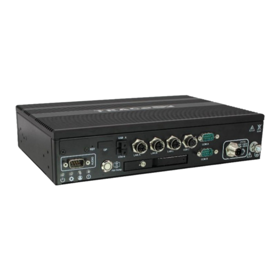
- Page 1 USER GUIDE TRACe-B104-TR D271626-1.0 - July 2023 www.kontron.com...
- Page 2 D271626 – TRACe-B104-TR USER GUIDE This page has been intentionally left blank www.kontron.com // 2...
- Page 3 TRACe-B104-TR USER MANUAL Disclaimer Kontron would like to point out that the information contained in this user guide may be subject to alteration, particularly as a result of the constant upgrading of Kontron products. This document does not entail any guarantee on the part of Kontron with respect to technical processes described in the user guide or any product characteristics set out in the user guide.
-
Page 4: Intended Use
PRODUCTS COULD LEAD DIRECTLY TO DEATH, PERSONAL INJURY, OR SEVERE PHYSICAL OR ENVIRONMENTAL DAMAGE (COLLECTIVELY, "HIGH RISK APPLICATIONS"). You understand and agree that your use of Kontron devices as a component in High Risk Applications is entirely at your risk. To minimize the risks associated with your products and applications, you should provide adequate design and operating safeguards. -
Page 5: Revision History
If you have any difficulties using this user guide, discover an error, or just want to provide some feedback, contact Kontron support. Detail any errors you find. We will correct the errors or problems as soon as possible and post the revised user guide on our website. -
Page 6: Symbols
D271626 – TRACe-B104-TR USER GUIDE Symbols The following symbols may be used in this user guide DANGER indicates a hazardous situation which, if not avoided, will result in death or serious injury. WARNING indicates a hazardous situation which, if not avoided, could result in death or serious injury. - Page 7 D271626 – TRACe-B104-TR USER GUIDE This symbol indicates that the product shall be supplied by a DC power voltage. This symbol indicates general information about the product and the user guide. This symbol also indicates detail information about the specific product configuration.
-
Page 8: For Your Safety
However, the life expectancy of your product can be drastically reduced by improper treatment during unpacking and installation. Therefore, in the interest of your own safety and of the correct operation of your new Kontron product, you are requested to conform with the following guidelines. -
Page 9: Lithium Battery Precautions
In order to maintain Kontron’s product warranty, this product must not be altered or modified in any way. Changes or modifications to the product, that are not explicitly approved by Kontron and described in this user guide or received from Kontron Support as a special handling instruction, will void your warranty. - Page 10 D271626 – TRACe-B104-TR USER GUIDE Environmental protection is a high priority with Kontron. Kontron follows the WEEE directive You are encouraged to return our products for proper disposal. www.kontron.com // 10...
-
Page 11: Table Of Contents
1.2.1. Main Features ..............16 1.2.2. TRACe-B104-TR Block Diagram ..........19 1.2.3. Ordering Information ............20 1.2.1. I/O interfaces ............... 22 1.2.2. TRACe-B104-TR Front Side View ..........23 1.2.3. TRACe-B104-TR Rear Side View ..........23 1.2.4. Technical Specifications ............. 23 1.2.5. MTBF ................. 26 1.3. - Page 12 3.1.2. Unpacking ..............41 3.2. Contents ............... 41 3.2.1. Optional Modules ............. 42 3.3. System Identification ............42 3.4. Plug and Play with TRACe-B104-TR ..........42 3.4.1. Plug ................. 43 3.4.2. Play (Refer to Linux Release Note) ........... 44 Physical I/Os ....................................... 45 4.1.
-
Page 13: List Of Tables
Table 15: Status User LEDs Description ..........56 Table 16: Efficiency vs Input voltage: ..........58 Table 17: TRACe-B104-TR Consumption: based on current measurement ....58 Table 18: Electrical specifications of the IGN control input signal ....61 Table 19: Supported graphics unit .......... - Page 14 D271626 – TRACe-B104-TR USER GUIDE Figure 26: DC IN connector ............45 Figure 27: Gigabit Ethernet connector ..........46 Figure 28: USB2.0 connector ............47 Figure 29: COM A and COM B Serial connectors ........48 Figure 30: DIO connector ............49 Figure 31: Audio connector ............
-
Page 15: 1/ Introduction
(e.g. drivers and BSPs) are described in detail in separate guides (see Appendix A "Associated Documentation"). This hardware technical documentation reflects the most recent version of the product. In this document, TRACe-B104-TR stands for all variants listed in the Ordering Information chapter 1.2.3 1.1.2. -
Page 16: Main Features
D271626 – TRACe-B104-TR USER GUIDE The Kontron TRACe-B104-TR can take over typical on-board wireless functions, whether it is an Internet connection for passengers or locating the vehicle. The three M.2 slots (which two of them linked to two nano-SIM slots and dual SIM support) provide maximum flexibility in implementing mobile service standards up to 5G/4G LTE or Wi-Fi/ IEEE 802.11, GNSS and derivates. - Page 17 A dedicated web site is also available for online updates and release downloads. The TRACe-B104-TR system is provided with the BIOS AMI Aptio V UEFI and supporting Linux Fedora remix distribution. Windows 10 BSP is also available for our customers.
- Page 18 Security Solution The key for Kontron with this new module platform is security. The TRACe-B104-TR is provisioned with a TPM2.0 (Trusted Platform Module) security chip, securing system software by enabling trusted boot operation on Linux with x86 and by verifying local or remote attestation. It ensures secure SSL/TLS network communication by enabling authentication and by providing associated certificate and private keys.
-
Page 19: Trace-B104-Tr Block Diagram
D271626 – TRACe-B104-TR USER GUIDE 1.2.2. TRACe-B104-TR Block Diagram Figure 2: TRACe-B104-TR Functional Bloc Diagram Modems / SIM cards Operational Insulated area Connectors CPLD Power Ctrl3 3x M.2 Sockets USB2.0 USB C USB2.0 Galvanic-Isolation M12 A Code SIM 1 SIM0 Tranceiver M.2 Key B1 (3042/3050) -
Page 20: Ordering Information
- No Operating System - EN50155 Class OT3 - Includes Wall mounting kit, 2 years warranty. 1057-2113 TRACE-KIT-CAB- Set of Cables for TRACe-B104-TR evaluation, consisting of: EVAL 1x Cable ASSY: Power (M12-A coded to free end), 1x Ethernet (M12-X coded to RJ-45),... - Page 21 D271626 – TRACe-B104-TR USER GUIDE 1058-7259 TRACE-PSUASSY TRACe AC PSU / Adapter 100-240VAC to 24VDC with M12 DC-IN connector. FOR LAB USE. Only usable on TRACE-B104-Mx2-00000C-V-0 24/48VDC nominal voltage variants. www.kontron.com // 21...
-
Page 22: I/O Interfaces
D271626 – TRACe-B104-TR USER GUIDE 1.2.1. I/O interfaces Table 2: I/O interfaces LOCATION FEATURE DESCRIPTION Operational DC IN 1x DC IN with ignition power control, insulated, on M12 A- external Power coded male connector (4 pins) I/Os Connector Refer to input power supply specification and pinout... -
Page 23: Trace-B104-Tr Front Side View
Intel Atom® x6425E, quad core @2.0 GHz Support of Intel® VT-x virtualization Virtualization TPM2.0, secure boot support Security Linux 64 bits, Windows 10 on-request, Kontron SEC-Line firmware (hardened openWRT) soon Graphics Integrated Intel® UHD Graphics for 10th Gen Intel® Processors, 32EUs, max resolution 4096x2160@ 60Hz... -
Page 24: Table 3: Trace-B104-Tr Mechanical Specifications
D271626 – TRACe-B104-TR USER GUIDE 16 GByte DDR4 3200 MT/s (z=3) Mass Storage 64 GByte industrial grade eMMC soldered Flash 2x SATA III links: 1 towards internal M.2 slot, 1 towards external drive bay for removable 2,5” SATA SSD/HDD Insulated User I/Os... -
Page 25: Figure 5: Trace-B104-Tr Dimensions - Front Side Overview (In Mm)
D271626 – TRACe-B104-TR USER GUIDE Figure 5: TRACe-B104-TR Dimensions - front side overview (in mm) Figure 6: TRACe-B104-TR Dimensions - Top View (in mm) www.kontron.com // 25... -
Page 26: Mtbf
D271626 – TRACe-B104-TR USER GUIDE Figure 7: TRACe-B104-TR Dimensions - Bottom View (in mm) Figure 8: TRACe-B104-TR - Side View 1.2.5. MTBF MTBF reliability prediction is made according to the IEC TR 62380 standard. MTBF is higher than 200,000 hrs @ 40°C in the basic configuration without any optional peripheral devices (SSD/HDD, mini PCIe modules). -
Page 27: Environmental Specifications
D271626 – TRACe-B104-TR USER GUIDE 1.3. Environmental Specifications 1.3.1. Operating and Storage Conditions Table 4: TRACe-B104-TR Operating and storage Conditions Operating Temperature Up to -25°C to +70°C at sea level (0 m) Operating temperature only valid for qualified Kontron configurations (excluding M.2 / mPCIe and HDD/SDD peripheral devices). - Page 28 D271626 – TRACe-B104-TR USER GUIDE EMI & EMC compatibility §13.4.8 EN50121-3-2:2015 Insulation and dielectric tests EN50155:2021 §13.4.9 Vibration, shock and bump test EN61373:2011 category 1, class B §13.4.11 Water tightness test (Ingress EN60529:2000 IP20 protection) §13.4.12 Declaration of product conformity and product compliance certificates are available on request.
-
Page 29: 2/ Installation Instructions
The TRACe-B104-TR housing is based on an aluminum box with connectors for external interfacing including a case ground point. The TRACe-B104-TR is designed for ambient air convection cooling. As the unit does not have a fan for forced air cooling, integrators must verify the application cooling design prior to integration in an application. -
Page 30: Mounting Pre-Requisites
Grounding Point Cabling 2.4. Module integration Three M.2 and one miniPCIe internal slots are available inside the TRACe-B104-TR. Refer to 4.3 for more information about the slots. Expansion card installation should be performed before installing the TRACe computer in operational environment cabinet. -
Page 31: Installing The Modules
D271626 – TRACe-B104-TR USER GUIDE Figure 10: Position of the M.2 and miniPCIe slots 2.4.3. Installing the modules Insert the module in its slot following the standard recommendations and lock it with the dedicated screw: torque = 0.14N.m + add Loctite 222. -
Page 32: Closing The System
2.5.1. Lateral mounting brackets installation The TRACe-B104-TR system will be mounted by its lateral mounting brackets (one on each side). The two brackets and 8x M3 screws are provided with the system. The screws have nylon patch pre- applied and shall be used without adding thread locker. -
Page 33: Installation Inside The Cabinet
D271626 – TRACe-B104-TR USER GUIDE 2.5.2. Installation inside the cabinet The system shall be attached to the cabinet with four M5 screws (of 16 mm minimum length, assembled with adapted washers, ISO 7089 series recommended). The torque will depend on the mounting surface under responsibility of the installer. -
Page 34: Physical Orientation
D271626 – TRACe-B104-TR USER GUIDE 2.6. Physical Orientation The equipment is in its normal position of use when arrow is vertical and upwards oriented as described below. 2.6.1. Horizontal Wall Mounting Figure 15: Horizontal Mount 2.6.2. Vertical Wall Mounting Figure 16: Vertical Mount 2.7. -
Page 35: Horizontal Orientation
D271626 – TRACe-B104-TR USER GUIDE In order to have a sufficient air circulation around the device, we recommend not mounting or operate any other devices within the “Keep Out Area” around the TRACe-B104-TR; refer to the blue marked area in following figures. -
Page 36: Vertical Orientation
D271626 – TRACe-B104-TR USER GUIDE 2.7.2. Vertical orientation The keep out area is defined by the following minimal distances: Direction +X : 2*h Direction +Y : 2*h Direction +Z : 3*h Direction -X : 0... -
Page 37: Grounding Point Cabling
This is accomplished via the ground point indicated by the ground symbol on the operational side of the TRACe-B104-TR, it is a threaded blind stud which accepts an M6 screw or bolt for attaching external ground cabling to the TRACe-B104-TR. This grounding wire must be connected to the vehicle’s chassis or a central grounding point. - Page 38 D271626 – TRACe-B104-TR USER GUIDE Disk Installation ESD Sensitive Device! Care must be taken during all handling operations and inspections of this product in order to ensure product integrity at all times. If the drive bay is locked, use the key to unlock it by rotating the key 90 degrees clockwise.
-
Page 39: Cover Plate Assembly
2.12. Cover Plate Assembly The cover plate is required on TRACe-B104-TR in operating conditions. During TRACe-B104-TR maintenance, the operator can remove the cover plate to get access to the SIM sockets. Hereinafter a picture shows mounting screws attaching the cover plate. Please note that a locking agent should be applied on mounting screws before attaching the cover plate. - Page 40 D271626 – TRACe-B104-TR USER GUIDE www.kontron.com // 40...
-
Page 41: 3/ Getting Started With Trace-B104-Tr
D271626 – TRACe-B104-TR USER GUIDE 3/ Getting Started with TRACe-B104-TR This section describes the main recommendations before starting to plug and play with the TRACe system. If the TRACe product must be installed in railway environment, refer to Installation Instructions section before starting to plug and play. -
Page 42: Optional Modules
The following sections are valid for a Linux operating system with its TRACe-B104 BSP installed. A live CD Linux image is available on the Kontron Web Site under EMD customer section. See Chapter 2 - Installation Instructions when deploying the TRACe system in final operational environment. -
Page 43: Plug
3.4.1.2. DC IN Power Connection The TRACe-B104-TR DC IN power must be connected by a M12 DC IN connector to a DC power source via a DC power supply cable. It is recommended that the last connection attached to the system should be the power cable. -
Page 44: Play (Refer To Linux Release Note)
3.4.2. Play (Refer to Linux Release Note) To use the BSP Fedora 36 remix image provided by Kontron, install specific packages on a different Linux version or build you own customized live image, please refer to “TRACe-B1 Linux BSP Fedora 36 Remix Live - Release Notes” document (ref. D275466) www.kontron.com... -
Page 45: 4/ Physical I/Os
D271626 – TRACe-B104-TR USER GUIDE 4/ Physical I/Os 4.1. Front Side 4.1.1. DC IN Power Supply Connector The DC IN power supply connector located on operational panel is a M12 Connector, Male, 4 Pins, A-coded. The keying of the connector is oriented downward on the equipment. -
Page 46: Lan A, Lan B And Lan C Gigabit Ethernet Connectors
D271626 – TRACe-B104-TR USER GUIDE 4.1.2. LAN A, LAN B and LAN C Gigabit Ethernet Connectors The Gigabits Ethernet connectors LAN A, LAN B and LAN C located on front panel are available as M12 Connectors, Female, 8 Pins, X-coded. The interfaces provide automatic detection and switching between 10BASE-T, 100BASE-TX and 1000BASE-T data transmission (Auto-Negotiation). -
Page 47: Usb C: Usb2.0 Connector
D271626 – TRACe-B104-TR USER GUIDE 4.1.3. USB C: USB2.0 connector One USB2.0 port is available on front panel as M12 Connector, Female, 5 pins, A-coded. Backward- compatible with USB1.1. Figure 28: USB2.0 connector Table 8: USB2.0 connector pin assignement SIGNAL... -
Page 48: Com A, Com B: Serial Connectors
D271626 – TRACe-B104-TR USER GUIDE 4.1.4. COM A, COM B: Serial Connectors Two serial ports RS232/422/485 (configuration can be selected under BIOS or OS) are available on COM A and COM B, DB9 male connectors. Standoffs of D-Sub connectors have 4-40 UNC thread pitch. -
Page 49: Dio : Digital Inputs / Outputs Connector
D271626 – TRACe-B104-TR USER GUIDE 4.1.5. 4.1.5. Audio Connector Differential Stereo Line In, Mic In and Stereo Line Out are available on Audio DB9 female connector. Standoffs of D-Sub connectors have 4-40 UNC thread pitch. Figure 30: Audio connector Table 10: Audio connector Pin Assignment... -
Page 50: Dp: Displayport Connector
D271626 – TRACe-B104-TR USER GUIDE 4.1.6. DP: DisplayPort Connector The TRACe-B104-TR has a DisplayPort Interface on standard DP connector. Figure 31: DisplayPort Connector Table 11: DisplayPort Connector Pin Assignment NAME SIGNAL DESCRIPTION ML_Lane 0 (p) Lane 0 (positive) Ground ML_Lane 0 (n) -
Page 51: Usb A And Usb B Connectors
D271626 – TRACe-B104-TR USER GUIDE 4.1.7. USB A and USB B Connectors The TRACe-B104-TR has two USB type A, USB 3.1/2.0 compliant connectors. Figure 32: USB 3.1 connector Table 12: USB 3.1/2.0 Connector Pin Assignment SIGNAL DESCRIPTION +5V protected USB power... -
Page 52: Sim Cards: Sim Connectors
D271626 – TRACe-B104-TR USER GUIDE 4.1.8. SIM CARDS: SIM Connectors The TRACe-B104-TR has 4x SIM sockets for Nano SIM (4FF) cards. Figure 33: SIM Connectors Table 13: SIM connector pin assignment SIGNAL DESCRIPTION Power Reset Clock Not connected Ground Programming power (not used) -
Page 53: 2"5 Drive Bay
D271626 – TRACe-B104-TR USER GUIDE 4.1.9. 2”5 Drive Bay The TRACe-B104-TR system integrates one removable 2”5 drive bay on front panel for 2,5‘‘ SATA III disk. Supported HDD thickness: up to 9.5mm Figure 34: Drive bay and Hot swap button www.kontron.com... -
Page 54: Power Status And User Leds
D271626 – TRACe-B104-TR USER GUIDE 4.1.10. Power Status and User LEDs Figure 35: TRACe-B104 LEDs Five LEDs are available on front side of TRACe-B104-TR: Power LED Alarm LED System LED Hotswap LED User LED Table 14: Status User LEDs Description... -
Page 55: Reset
D271626 – TRACe-B104-TR USER GUIDE 4.1.11. Reset User may reset the system by pushing reset button located on front panel face. Figure 36: Computer Reset The reset switch can also be used to wakeup the system from a sleep mode www.kontron.com... -
Page 56: Rear Side
D271626 – TRACe-B104-TR USER GUIDE 4.2. Rear Side 4.2.1. DIO : Digital Inputs / Outputs connector 4 isolated general purpose Digital Inputs and 4 isolated general purpose Digital Outputs are available on a DB25 female connector. Standoffs of D-Sub connectors have 4-40 UNC thread pitch. -
Page 57: Expansion Sockets
D271626 – TRACe-B104-TR USER GUIDE 4.3. Expansion Sockets The TRACe system offers 3x M.2 + 1x miniPCIe internal slots with the following interface compatibility (see also section 1.2.2 - TRACe Block Diagrams). miniPCIe slot: Accepts only full size (F2 type only) miniPCIe cards Available interfaces: PCIe and USB2.0... -
Page 58: 5/ Power And Thermal Specifications
>89% >90% >89% 5.1.1.2. Input Voltage Interruption The TRACe-B104-TR product is compliant with EN50155 Class S2. Then, interruptions of up to 10 ms are permitted on power input voltage. 5.1.2. Power Consumption The power consumption tables below list the voltage and power specifications for the TRACe-B104- TR system. -
Page 59: Inrush Current
To ensure monitoring inside the box, the TRACe system get temperature from thermal sensors integrated in the processor. Default critical voltage and temperature sensor thresholds are set on TRACe-B104-TR system to protect system from damage and secure system reliability. Above those critical thresholds, system will warn or force a system shutdown depending on the error severity level detected. -
Page 60: Thermal Considerations
The physical size, shape, and construction of the chassis ensure the lowest possible thermal resistance in natural convection environment and in horizontal or vertical position. To cool the TRACe-B104-TR system in well conditions, free minimal volume shall be respected around the system. This free volume is defines in section 2.7. -
Page 61: 6/ Additional System Features
D271626 – TRACe-B104-TR USER GUIDE 6/ Additional System Features 6.1. Ignition A power off controlled by the IGN signal has the same impact than removing VDC: all PSUs are switched off including standby power supplies. However using IGN to power on/off is recommended... -
Page 62: Rtc
The intention is to bring the system back from the nonresponsive state to normal operation. The TRACe-B104-TR CPLD implements a watchdog timer with power-cycle and pretimeout support. It is managed by the trace-b1-cpld-wdt module. Refer to “TRACe-B1 Linux BSP Fedora 36 Remix Live - Release Notes” document (ref. D275466) 6.3.2. -
Page 63: Display Resolution
D271626 – TRACe-B104-TR USER GUIDE 6.5.2. Display Resolution Table 21: Supported Maximum Display Resolution Standard Supported Maximum Resolution 4096x2160@ 60Hz www.kontron.com // 63... -
Page 64: 7/ Uefi Bios
7/ uEFI BIOS 7.1. Starting the uEFI BIOS The TRACe-B104-TR is provided with a Kontron-customized, pre-installed and configured version of Aptio ® V uEFI BIOS based on the Unified Extensible Firmware Interface (uEFI) specification and the Intel® Platform Innovation Framework for EFI. This uEFI BIOS provides a variety of new and enhanced functions specifically tailored to the hardware features of the TRACe-B104-TR. -
Page 65: Setup Menus
D271626 – TRACe-B104-TR USER GUIDE 7.2. Setup Menus The Setup utility features menus listed in the selection bar at the top of the screen: Main Advanced Chipset Security Boot Save & Exit The left and right arrow keys select the Setup menus. The currently active menu and the currently active uEFI BIOS Setup item are highlighted in white. -
Page 66: Technical Support
D271626 – TRACe-B104-TR USER GUIDE 8/ Technical Support For technical support, contact our Support Department: E-Mail: support.KFR@kontron.com Phone: +33-498-163-400 Make sure you have the following information available when you call: Product ID Number (PN), Serial Number (SN) The serial number can be found on the Type Label, located on the product’s rear side. -
Page 67: Returning Defective Merchandise
RMA number. The buyer accepts responsibility for all freight charges for the return of goods to Kontron’s designated facility. Kontron will pay the return freight charges back to the buyer’s location in the event that the equipment is repaired or replaced within the stipulated warranty period. -
Page 68: Appendix: Associated Documentation
D271626 – TRACe-B104-TR USER GUIDE Appendix: Associated Documentation The following documentation is available on the Kontron website: Datasheet TRACe-B104-TR D275466 TRACe-B1 Linux BSP Fedora 36 Remix Live - Release Notes Please contact sales.KFR@kontron.com for any further information www.kontron.com... -
Page 69: About Kontron
With its standard and customized products based on highly reliable state-of-the-art technologies, Kontron provides secure and innovative applications for a wide variety of industries. As a result, customers benefit from accelerated time-to-market, lower total cost of ownership, extended product lifecycles and the best fully integrated applications.
Need help?
Do you have a question about the TRACe-B104-TR and is the answer not in the manual?
Questions and answers