
Related Manuals for Kontron KBox R-101


Summary of Contents for Kontron KBox R-101
- Page 1 USER GUIDE KBox R-101 User Guide Rev. 1.0 Doc. ID: 1073-2136 www.kontron.com // 1...
- Page 2 KBox R -101 User Guide Rev. 1.0 This page has been intentionally left blank www.kontron.com // 2...
- Page 3 Kontron with respect to technical processes described in the user guide or any product characteristics set out in the user guide. Kontron assumes no responsibility or liability for the use of the described product(s), conveys no license or title under any patent, copyright or mask work rights to these products and makes no representations or warranties that these products are free from patent, copyright or mask work right infringement unless otherwise specified.
- Page 4 ENVIRONMENTAL DAMAGE (COLLECTIVELY, “HIGH RISK APPLICATIONS”). You understand and agree that your use of Kontron devices as a component in High Risk Applications is entirely at your risk. To minimize the risks associated with your products and applications, you should provide adequate design and operating safeguards.
- Page 5 If you have any difficulties using this user guide, discover an error, or just want to provide some feedback, contact Kontron Support. Detail any errors you find. We will correct the errors or problems as soon as possible and post the revised user guide on our website.
-
Page 6: Symbols
Eye protection per manufacturer notice shall review before servicing. This symbol indicates general information about the product and the user guide. This symbol also indicates detail information about the specific product configuration. This symbol precedes helpful hints and tips for daily use. www.kontron.com // 6... -
Page 7: For Your Safety
Therefore, in the interest of your own safety and of the correct operation of your new Kontron product, you are requested to conform with the following guidelines. -
Page 8: Lithium Battery Precautions
General Instructions on Usage In order to maintain Kontron’s product warranty, this product must not be altered or modified in any way. Changes or modifications to the product, that are not explicitly approved by Kontron and described in this user guide or received from Kontron Support as a special handling instruction, will void your warranty. -
Page 9: Table Of Contents
4.4. Cover (u-form) ......................................32 4.5. Base ..........................................33 4.6. Internal Features ..................................... 33 4.6.1. RTC Supercap Buffer ................................... 33 Thermal Management ..................................34 5.1. Passive Cooling ......................................34 5.2. Heatsink ........................................34 5.3. Installation Orientation ..................................34 www.kontron.com // 9... - Page 10 11.4.4. Access to the USER Partition of the EEPROM ..........................62 11.4.5. Reset Firmware ....................................62 Product Specification ..................................63 12.1. Block Diagram ......................................63 12.2. Hardware Specification ..................................65 12.3. Software Specification ..................................66 12.4. Power Specification ....................................66 12.4.1. Power Supply Protection Requirements ............................. 67 www.kontron.com // 10...
-
Page 11: List Of Tables
16.1. Returning Defective Merchandise ..............................87 16.2. Warranty ........................................88 16.2.1. Limitation/Exemption from Warranty Obligation ........................88 List of Acronyms ......................................89 About Kontron ........................................90 List of Tables Table 1: Scope of Delivery ....................................19 Table 2: Accessories and Spare Parts ..............................20 Table 3: Ethernet Port Connection Speeds ............................. -
Page 12: List Of Figures
Figure 25: Debug GPS Information ................................53 Figure 26: Debug GPS Information 2 ................................. 53 Figure 27: Exit Debug Mode ..................................54 Figure 28: Block Diagram KBox R-101-TGL ............................. 63 Figure 29: Block Diagram KBox R-101-EKL .............................. 64 Figure 30: Mechanical Dimensions (mm) ..............................69 Figure 31: Mechanical Dimensions with Wall Mount Brackets (mm) .................... -
Page 13: 1/ Introduction
EN 50155 compliance, IP54 protection, M12 connectors and an extended temperature range. The passively cooled KBox R-101 series uses a u-form cover as a heatsink encompassing the top, and left and right sides. The fanless design ensures a significantly prolonged lifespan and high system availability. - Page 14 Without internal fuse (Prerequisite: DC power supply with mandatory external 5AT fuse or safety device) With internal fuse To ensure you have the latest version of this user guide, visit Kontron’s Embedded Box PC, KBox R-Series website. www.kontron.com // 14...
-
Page 15: 2/ General Safety Instructions
Only connect the product to an external power supply providing the voltage type (AC or DC) and the input power (max. current) specified on the Kontron Product Label and meeting the requirements of the Limited Power Source (LPS) and Power Source (PS2) of UL/IEC 62368-1 . -
Page 16: Instructions Générales De Sécurité
Le non-respect des consignes de sécurité générales suivantes peut entraîner des blessures pour l'utilisateur et/ou des dommages pour le produit. En cas de non-respect des consignes, Kontron Europe est exonéré de la responsabilité en cas d'accident, ceci s'applique également pendant la période de garantie. -
Page 17: Electrostatic Discharge (Esd) Precautions
Cover workstations with approved antistatic material. Always wear a wrist strap connected to workplace. Always use properly grounded tools and equipment. Use antistatic mats, heel straps, or air ionizers for more protection. Always handle electrostatically sensitive components by their edge or by their casing. www.kontron.com // 17... - Page 18 Keep work area free of non-conductive materials such as ordinary plastic assembly aids and Styrofoam. Use only field service tools that are conductive, such as cutters, screwdrivers, and vacuum cleaners. Always place drives and boards PCB-assembly-side down on the foam. www.kontron.com // 18...
-
Page 19: 3/ Shipment And Unpacking
If you notice shipping damage or inconsistencies between the contents and the original order, contact your dealer. 3.3. Scope of Delivery The scope of delivery describes the parts included in your KBox R-101 series delivery. Check that the delivery is complete, and contains the items listed. If damaged or missing items are discovered, contact your dealer. -
Page 20: Table 2: Accessories And Spare Parts
99 0700 29 05 without ferrules • AWG 16 with ferrules or AWG 14 without ferrules Cable: Outer diameter 8 mm to 13 mm Set KBox R-101 Service Cover Seal Loop Manufacturer: Silicon service cover seal loop cord (seal EMI/RFI) Kontron Article Number:... -
Page 21: Product Identification - Type Label
It is prohibited to connect the product to an external DC power supply without a 5AT fuse or safety device, if the product is configured with no internal fuse as stipulated on the type label (no-fuse symbol and warning text “External fuse mandatory 5AT”). Figure 2: Type label Examples KBox R-101-EKL 2-A0R1-2003 Product variant name Electrical specification... -
Page 22: 4/ Product Features
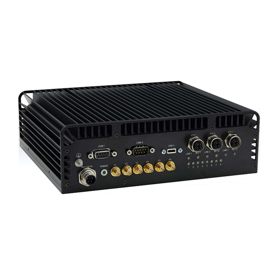
KBox R -101 User Guide Rev. 1.0 4/ Product Features The KBox R-101 series metal chassis is equipped with interfaces at the front and rear. The cover (u-form) functions as a heatsink encompassing the top, and left and right sides. -
Page 23: Power Led
Using the USB-C port as a service interface, the operator is able to realize a Display Port and a power supply for e.g. touch panels to facilitate debugging as well as commissioning. The USB-C port’s maximum power delivery is 5 V, 2 A. For the pin assignment, see Chapter 13.1.4: USB-C Port Connector (USB-C). www.kontron.com // 23... -
Page 24: Ethernet Ports (Eth1, Eth2, Eth3)
The three Ethernet ports (Figure 3, pos. 6, 7, 8) include link and activity status LEDs (Link1/2/3) and (Act1/2/3) (Figure 3, pos. 9). The connection speed of the three Ethernet ports depends on the KBox R-101 series variant (KBox R-101-TGL & KBox R-101-EKL). -
Page 25: Table 4: Wi-Fi And Bluetooth Module Specification Overview
2.4 GHz, 5 GHz, 6 GHz dual band 2x2 160 MHz Form Factor M.2 2230 Kontron recommends the use of Kontron’s Wi-Fi reference antenna chosen to meet RF performance requirements and with a nominal impedance of 50 ohms, see Table 2: Accessories and Spare Parts. -
Page 26: Table 5: Supported Frequency Bands Rat (5G, Lte, 3G)
5150–5925 MHz (TDD) 3550–3700 MHz (TDD) 1710–1780 MHz 2110–2200 MHz 663–698 617–65 3300–4200 MHz (TDD) 3300–3800 MHz (TDD) 4400–5000 MHz (TDD) Band support is firmware and type dependent Downlink only www.kontron.com // 26... -
Page 27: Table 6: 5G Module Specification (Sa & Nsa) Overview
LTE is realized using the SEMTECH/Sierra Wireless AirPrime EM7565 M.2 3042 module. Visit the manufacture’s website for the AirPrime EM7565 modules data sheet. The LTE module and 5G module use the same M.2 socket. The LTE module can only be implemented in the absence of a 5G module. www.kontron.com // 27... -
Page 28: Table 7: Supported Frequency Bands Rat (Lte, 3G)
KBox R -101 User Guide Rev. 1.0 Kontron recommends the use of Kontron LTE reference antenna, chosen to meet RF performance requirements and with a nominal impedance of 50 ohms, see Table 2: Accessories and Spare Parts. Table 7: Supported Frequency Bands RAT (LTE, 3G) -
Page 29: Service Cover
4.2. Service Cover The KBox R-101 series features a removable service cover on the rear side. Removing the service cover gives operators access to the product’s service panel. The service cover contains a replaceable seal loop on the inside for IP54 protection. -
Page 30: Service Panel
KBox R -101 User Guide Rev. 1.0 4.3. Service Panel The KBox R-101 series feature a service panel with the following interfaces, behind the service cover. Access the service panel by removing the service cover, see Chapter 6.1 Accessing the Service Panel. -
Page 31: Usb 2.0 Ports (Usb 2.0)
CFexpress Card Slot (CFexpress) The CFexpress slot supports CFexpress Type B cards with a PCIe Gen3, 1 lane interface. The Kontron reference CFexpress card supports up to 128 GByte storage. The CFexpress card is not hotplug capable and the product must be switched off properly before inserting or extracting the CFexpress card. -
Page 32: Cover (U-Form)
4.4. Cover (u-form) The KBox R-101 series features a cover (u-form) that functions as a heatsink with in-built cooling fins. On the left and right side of the cover are two threaded screw openings used to attach mounting brackets. The cover is sealed internally on all side. -
Page 33: Base
4.5. Base The KBox R-101 series features a base with no functional parts that may be installed directly on a flat surface. The type label is located on the product’s base next to the power connector. The adhesive seal label is placed on top of the screw above the type label, to prevent the operator from opening the product and invalidating the warranty. -
Page 34: 5/ Thermal Management
5/ Thermal Management 5.1. Passive Cooling The KBox R-101 series is passively cooled and fanless, using a cover (u-form) with in-built heatsink. 5.2. Heatsink The cover (u-form) functions as a heatsink with in-built cooling fins encompassing the maximum area (top, and left and right sides). -
Page 35: Minimum Clearance
KBox R -101 User Guide Rev. 1.0 5.4. Minimum Clearance To provide a maximum airflow away from the product, observe the minimum distances to surrounding parts. Kontron recommends that operators not to install or operate other devices within the specified keep out area around the product. -
Page 36: 6/ Preparing For Installation
KBox R -101 User Guide Rev. 1.0 6/ Preparing for Installation The KBox R-101 series is factory configured. Opening the cover invalidates the warranty (see Chapter 16.2: Warranty) and may cause damage to internal components and corrupt the product’s internal seal. Operators are only permitted to open the service cover to gain access to the interfaces on the service panel. -
Page 37: Inserting Or Extracting A Micro Sim Card(S)
Close the service cover as describe in Chapter 6.1: Accessing the Service Panel, step 3 and 4. After changing a storage device, the partitioning of the memory may differ and require repartitioning. Kontron reference CFexpress card is: • Transcend: TS128GCFE820I •... -
Page 38: 7/ Installation
7.1. Before Installing Before installing the KBox R-101 series in the field, ensure that the operating environment meets the specification as stated within this user guide. There must be sufficient space at the front of the product to access the Power IN connector, interface connectors and antennas. -
Page 39: Installation Orientation
KBox R -101 User Guide Rev. 1.0 7.2. Installation Orientation. When installing the KBox R-101 series in the field, install only horizontally (cover facing upward) or vertically (all directions). Operation of the product with the cover facing downwards is not permitted. -
Page 40: Installing With Wall Mount Brackets
KBox R -101 User Guide Rev. 1.0 7.3. Installing with Wall Mount Brackets To install the KBox R-101 series in the field using the wall mount brackets provided in the delivery, perform the following: Attach the wall mounting brackets firmly to the left and right sides of the product using the two M3x6 screws provided (Figure 13, pos. -
Page 41: Installing With 19" Rack Mount Brackets
Fasten both 19” rack mount brackets to the front side posts of the 19” industrial rack cabinet using all four screws and cage nuts (to be provided by the operator) to provide full support for the product’s weight. www.kontron.com // 41... -
Page 42: Figure 15: Attaching The 19" Rack Mount Brackets
Rack mount bracket (L-shape) right To install the KBox R-101 series in the field using the 19” rack mount bracket set, perform the following: Attach the 19” rack mount brackets firmly to the left and right sides of the product using the two M3x6 screws provided (Figure 15 pos. -
Page 43: 8/ Starting Up
8/ Starting Up 8.1. Before Starting Up Before starting up the KBox R-101 series read the instructions in this user guide and observe the safety instructions in Chapter 2/General Safety Instructions. If connected incorrectly the product may malfunction or short circuit leading to product damage or serious injury. -
Page 44: Wiring The M12 Mating Power Connector
The product is delivered with the required M12 mating power connector. To order a replacement M12 mating power connector, see Table 2: Accessories and Spare Parts. For the M12 mating power connector’s pin assignment, with a description of the ignition feature, see Chapter 13.1.1: M12 Power IN Connector. www.kontron.com // 44... -
Page 45: Starting Up
8.4. Operating System (OS) and Drivers The KBox R-101 series comes hardware configured, and on request with a pre-installed operating system and all the necessary drivers (in accordance with the ordered hardware configuration). No further internal configuration is required, enabling full operation when connected to power for the first time. -
Page 46: Switching Off
Disconnect the power cable from the Power IN connector on the front panel or the external DC power supply. Once switched off properly the interface connectors and antenna cable may be disconnected. Remove the ground cable from the protective earth bolt. www.kontron.com // 46... -
Page 47: 9/ Setting Up
9.1. Before Setting Up All software installed by the operator is at the operator’s own risk. Kontron is not responsible for any malfunction, data loss, outage of various services and other problems caused by software installed by the operator. Kontron is not responsible for the loss of stored, transmitted, received and used data. -
Page 48: Figure 18: Network Manager
During set up of the new APN, the correct APN of the used provider must be filled in. Depending on the provider, a username and password may be required. Figure 19: Add an APN (Access Point Name) www.kontron.com // 48... -
Page 49: Figure 20: Activate Apn
KBox R -101 User Guide Rev. 1.0 Select the new configured APN. Figure 20: Activate APN Enable “Data Roaming“, for devices with contracts requiring “Data Roaming“, even if the device is in the device’s home country. Figure 21: Roaming www.kontron.com // 49... -
Page 50: Figure 22: Modem Details
KBox R -101 User Guide Rev. 1.0 Check the connection under “Modem Details“. Figure 22: Modem Details www.kontron.com // 50... -
Page 51: Testing The Mobile Network Connection Under Linux
For example: AT!GSTATUS? AT!LTEINFO? AT!GPSSTATUS? AT!GPSSATINFO? AT!GPSLOC? AT!RESET The AT Command Reference Guide contains more commands: For more AT commands, download the AT Command Reference Guide for the EM9191 5G module or the AirPrime EM7565 LTE module. www.kontron.com // 51... -
Page 52: Figure 24: Debug Lte Information
KBox R -101 User Guide Rev. 1.0 Figure 24: Debug LTE Information www.kontron.com // 52... -
Page 53: Figure 25: Debug Gps Information
KBox R -101 User Guide Rev. 1.0 Figure 25: Debug GPS Information Figure 26: Debug GPS Information 2 www.kontron.com // 53... -
Page 54: Setting Up The Indicator Leds
Follow the GPIO. Readme Instructions for driver usage and supported features The Kontron PLD driver is part of the stable Linux Kernel compatible with Rev. 3.11 or later. Supported hardware and features depend on the Kernel revision and may differ from the driver available here. -
Page 55: 10/ Bios
No legacy support and no Master Boot Record (MBR) installation. Only use the Kontron provided tools! The KBox R-101 series uses the AMI Aptio V uEFI BIOS based on the Unified Extensible Firmware Interface (uEFI) specification. 10.1. Starting the uEFI BIOS The uEFI BIOS’s Setup program provides quick and easy access to the individual function settings for control or... -
Page 56: Bios Navigation
<RETURN> key executes a command or selects a submenu 10.4. Getting Help The Setup menu’s right frame displays a help window. The help window provides an explanation of the respective BIOS function. Register for Kontron’s Customer Section to access further BIOS Information. www.kontron.com // 56... -
Page 57: Bios Updates
Kontron recommends regular BIOS updates, to ensure compatibility with a new operating system, hardware, software or to integrate new BIOS functions. Additionally, if a problem cannot be solved using a new driver, Kontron recommends updating the BIOS. Before updating the BIOS, Kontron’s recommends making a backup of the current BIOS setting. -
Page 58: 11/ Board Management Controller (Bmc)
BMC Firmware Application When booting the KBox R-101 series, the controller starts the BMC bootloader. The BMC bootloader is responsible for verifying, whether a firmware application is available at a certain memory location in the controller. If a firmware application is available, the BMC bootloader hands over to the firmware application that performs a startup and controls the board. -
Page 59: Download A Firmware Application
The new firmware application is downloaded to the controller flash. After the download and verification, the KBox R-101 series must be switched off and switch on again, to be able to run the new downloaded version of the firmware application. -
Page 60: Bmc Firmware Application
The firmware application performs various duties when started automatically by the bootloader. Most duties are performed automatically and others duties can be controlled by the KEAPI (Kontron’s embedded API). For KEAPI information, see Chapter 11.3.2: Access to the Firmware Application. -
Page 61: Special Considerations With The Firmware Application
The firmware application sets a counter every 10 minutes and saves the information in the internal EEPROM that is not accessible to the operator. This value can be read (but not written) via the KEAPI. For example, a counter value of 360 means, the KBox R-101 series is running for 3600 minutes. 11.4.2. -
Page 62: Access To The User Partition Of The Eeprom
The firmware application can be reset via KEAPI. This command only resets the firmware, but not the operating system. When sending this command, a loss of the interface to the BMC might occur on the operating system side. www.kontron.com // 62... -
Page 63: 12/ Product Specification
KBox R -101 User Guide Rev. 1.0 Product Specification 12.1. Block Diagram The KBox R-101-TGL implements a COM Express (COMe) module (COMe-cTL6) on a baseboard with standardized open platform interface connectors and optional network connectivity (Wi-Fi and LTE/5G). Figure 28: Block Diagram KBox R-101-TGL... -
Page 64: Figure 29: Block Diagram Kbox R-101-Ekl
KBox R -101 User Guide Rev. 1.0 The KBox R-101-EKL implements a COM Express (COMe) module (COMe-cEL6) on a baseboard with standardized open platform interface connectors and optional network connectivity (Wi-Fi and LTE/5G). Figure 29: Block Diagram KBox R-101-EKL KBox R-101-EKL... -
Page 65: Hardware Specification
KBox R -101 User Guide Rev. 1.0 12.2. Hardware Specification Table 13: Hardware Specification KBox R-101-TGL KBox R-101-EKL Processor Core™ i7-1185GRE Core™ i5-1145GRE Atom® X6425RE Atom® X6212RE (integrated Chipset) 1.8 GHz Base freq. 1.9 GHz Base freq. 1.9 GHz Base freq. -
Page 66: Software Specification
AMI Aptio V5 12.4. Power Specification Before connecting the KBox R-101 series to an external DC power supply, ensure that the external DC power supply meets the product’s electrical specification (Table 15) and that protection and supply limitations have been taken into consideration. -
Page 67: Power Supply Protection Requirements
10 ms, a recovery time of 2 s must be maintained to allow internal voltages to discharge sufficiently. Failure to observe the specified recovery time of 2 s between switching off and switching on the product, may lead to malfunction. For recovery time information, contact Kontron Support. 12.4.1. -
Page 68: Environmental Specification
Salt Mist (non-operating) According to: EN 50155 - EN 60068-2-11 – Test Ka: Salt Mist 3,000 m (9,840 feet) maximum Altitude (operating) 10,000 m (32,800 feet) Altitude (non-operating) IP54 IP Protection Class MTBF 187,747.94 hours KBox R-101-TLE-i5i-0-256-0-0-0-1-0-000 www.kontron.com // 68... -
Page 69: Mechanical Specification
220 mm x 70 mm x 200 mm (8.66” x 2.76” x 7.87”) Chassis Aluminum black anodized Front Panel Aluminum Cooling Solution Fanless operation, natural convection Weight 3.1 kg/6.8 Ibs. (approx.) Figure 30: Mechanical Dimensions (mm) To download the product’s Step files, visit Kontron’s Customer Section. www.kontron.com // 69... -
Page 70: Figure 31: Mechanical Dimensions With Wall Mount Brackets (Mm)
KBox R -101 User Guide Rev. 1.0 Figure 31: Mechanical Dimensions with Wall Mount Brackets (mm) To download the product’s Step files, visit Kontron’s Customer Section. www.kontron.com // 70... -
Page 71: Figure 32: Mechanical Dimensions With 19" Rack Mount Brackets (Mm)
KBox R -101 User Guide Rev. 1.0 Figure 32: Mechanical Dimensions with 19” Rack Mount Brackets (mm) To download the product’s Step files, visit Kontron’s Customer Section. www.kontron.com // 71... -
Page 72: Compliance
KBox R -101 User Guide Rev. 1.0 12.7. Compliance The KBox R-101 series complies with the requirements and the approximation of the laws relating to compliance for ‘Railway’, ‘CE’ or ‘RED’, and the standards (or later thereof) that are constitutional parts of the declaration. -
Page 73: Table 20: Compliance Ce
Wideband transmission systems - Data transmission equipment operating in the 2.4 GHz ISM band and using wide band modulation techniques EN 301 893 V2.1.1 5 GHz RLAN EN 301 908-1 V15.1.1 IMT cellular networks; Harmonized standard for access to radio spectrum; Part 1: Introduction and common requirement Release 15 www.kontron.com // 73... -
Page 74: Table 22: Country Compliance
EN 60068-2-64 Environmental testing - Part 2-64: Random Vibration The KBox-R-101-TGL and KBox R-101-EKL plan to comply with the following country specific certifications (or later thereof). If the product is modified, the prerequisites for specific approvals may no longer apply. -
Page 75: 13/ Standard Interfaces - Pin Assignments
KBox R -101 User Guide Rev. 1.0 Standard Interfaces – Pin Assignments This chapter describes the KBox R-101 series available power, interface connectors, status LEDs, antenna and slots. 13.1. Front Panel All front panel connectors are IP54 compliant. 13.1.1. M12 Power IN Connector The Power IN connector is a 5-pin K code M12 connector with locking thread suitable for industrial applications and environments. -
Page 76: Power Led (Green)
Received Data differential pair receives data from the communications link. Power supply GND signal The two serial ports (COM1 and COM2) use different connector types, • COM1 is a 9-pin D-SUB (female) connector • COM2 is a 9-pin D-SUB (male) connector www.kontron.com // 76... -
Page 77: Usb-C Port Connector (Usb-C)
Antenna Connectors for Cellular Connection (LTE or 5G) (X3, X4, X5, X6) The four SMA (female) antenna connectors are suitable for industrial applications and environments and require a mating antenna cable with connector type SMA (male). The antenna connectors are IP54 compliant. www.kontron.com // 77... -
Page 78: M12 Ethernet Port Connectors (Eth1, Eth2, Eth3)
Ethernet connectors are IP54 compliant. For the KBox R-101-TGL, ETH1, ETH2 & ETH3 are 2.5 GbE and KBox R-101-EKL, ETH1 is 1 GbE & ETH2, ETH3 are 2.5 GbE. Table 27: 2.5 GbE Ethernet Port Pin Assignment (ETH1, ETH2, ETH3) -
Page 79: Configurable Leds (1,2,3,4,5,6,7,8)
LED to illuminate (yellow) in a set state. The configurable LEDs are IP54 compliant. For information on how to configure the LEDs, see Chapter 9.3: Setting Up the Indicator LEDs. www.kontron.com // 79... -
Page 80: Service Panel
The micro SIM cards are not part of the delivery and must be provided by the operator, to support the require network. The two SIM slots are only used in combination with 5G/LTE and are not available for storage. www.kontron.com // 80... -
Page 81: Cfexpress Card Slot (Cfexpress)
Cable adapter Detest signal for DP++ CONFIG2 Connected to Ground AUX+ Display Port Auxiliary channel differential pair (+) Ground AUX- Display Port Auxiliary channel differential pair (-) Hot Plug Detect Display Port hot plug detect Return Power for connector www.kontron.com // 81... -
Page 82: Usb 2.0 Port Connectors (Usb 2.0)
+5 V power supply for USB device Bottom_Data- USB 2.0 differential pair (-) Bottom_Data+ USB 2.0 differential pair (+) GND_Bottom Ground To achieve the specified performance for USB 2.0 use cabling that complies with the USB 2.0 standard. www.kontron.com // 82... -
Page 83: 14/ Maintenance
KBox R -101 User Guide Rev. 1.0 Maintenance The KBox R-101 series is factory configured and maintenance free. Opening the cover invalidates the warranty and may cause damage to internal components and corrupt the product’s internal seal. Operators are only permitted to open the product’s service cover to gain access to the interfaces on the service panel. -
Page 84: Cleaning
KBox R -101 User Guide Rev. 1.0 14.1. Cleaning Cleaning the KBox R-101 series is not a requirement, however Kontron recommends cleaning the product to remove dust and dirt to maintain the best conditions for cooling the product. When cleaning take into consideration, that the product is IP54 protected against dust in harmful quantities and water splashes on all sides. -
Page 85: Accessing The Service Panel
When reinstalling the service cover, operators must check that the seal loop: • Remains properly inserted within the service cover groove • Has no visible damaged • Has not suffered degradation such as cracking, hardness and reduced flexibility www.kontron.com // 85... -
Page 86: 15/ Storage And Transportation
15.1. Storage If it is necessary to store the KBox R-101 series, switch off properly by disconnecting the product from the external DC power supply, by removing the power cable from the Power IN connector or the external DC power supply. -
Page 87: 16/ Technical Support
RMA number. The buyer accepts responsibility for all freight charges for the return of goods to Kontron's designated facility. Kontron will pay the return freight charges back to the buyer's location in the event that the equipment is repaired or replaced within the stipulated warranty period. -
Page 88: Warranty
Limitation/Exemption from Warranty Obligation In general, Kontron shall not be required to honor the warranty, even during the warranty period, and shall be exempted from the statutory accident liability obligations in the event of damage caused to the product due to failure to observe the following: ... -
Page 89: List Of Acronyms
High Speed Packet Access Time Division Duplex Internet of Things Information Technology Equipment UEFI Unified Extensible Firmware Interface KEAPI UMTS Kontron Embedded API Universal Mobile Telecommunications System Local Area Network Universal Serial Bus Light-Emitting Diode Voltage Common Collector Long Term Evolution... -
Page 90: About Kontron
KBox R – User Guide Rev. 1.0 About Kontron Kontron is a global leader in IoT/Embedded Computing Technology (ECT). Kontron offers individual solutions in the areas of Internet of Things (IoT) and Industry 4.0 through a combined portfolio of hardware, software and services. With its standard and customized products based on highly reliable state-of-the-art technologies, Kontron provides secure and innovative applications for a wide variety of industries.
Need help?
Do you have a question about the KBox R-101 and is the answer not in the manual?
Questions and answers