
Related Manuals for Kontron KISS 2U V2


Summary of Contents for Kontron KISS 2U V2
- Page 1 » User’s Guide « KISS 2U V2 KISS 2U V2 KTQ87-A KISS 2U V2 PCI762-A User's Guide (Version 1.00) 1056-7538 www.kontron.com...
- Page 2 This page is intentionally left blank. www.kontron.com...
-
Page 3: Table Of Contents
1. Table of Contents KISS 2U V2 MB_SBC– User's Guide (Version 1.00) 1. Table of Contents 1. Table of Contents ............................. 1 1.1. Table of Figures............................3 2. Introduction ............................5 2.1. Symbols used in this Manual........................6 3. Important Instructions..........................7 3.1. - Page 4 12.4. Directives and Standards ........................44 13. Standard Interfaces – Pin Assignments ....................45 13.1.1. Serial Interface (RS232) ........................ 45 13.1.2. VGA Port ............................. 45 13.1.3. USB Port ............................. 46 14. Technical Support ..........................47 14.1. Returning Defective Merchandise ......................47 www.kontron.com...
-
Page 5: Table Of Figures
Fig. 12: USB ports on the front side........................ 17 Fig. 13: Rear side of the KISS 2U V2 with an SBC card (shown with a PCI-762 and an AC wide rage PSU) ....... 19 Fig. 14: External ports of PCI-762 SBC card ...................... 19 Fig. - Page 6 Fig. 39: Filtermatholder with filter mat......................39 Fig. 40: Filter mat ............................39 Fig. 41: Attached inner part of the slide rail (shown left side view of the KISS 2U V2 system) ........41 Fig. 42: KISS 2U V2 platform with slide rail in pulled-out position ................41 Fig.
-
Page 7: Introduction
Kontron Europe does not accept any liability for any printing errors or other inaccuracies in the manual unless it can be proven that Kontron Europe is aware of such errors or inaccuracies or that Kontron Europe is unaware of these as a result of gross negligence and Kontron Europe has failed to eliminate these errors or inaccuracies for this reason. -
Page 8: Symbols Used In This Manual
This symbol indicates that the system is equipped with hazardous moving parts. There is danger of injury to the user or the risk of damage to the product if the corresponding warning notices are not observed. Before maintenance and repair activities, the device must be disconnected from the power supply. www.kontron.com... -
Page 9: Important Instructions
In the event of damage to the device caused by failure to observe the included document “General Safety Instructions for IT Equipment”, the hints in this manual or eventually the warning signs label on the device, Kontron Europe shall not be required to honor the warranty even during the warranty period and shall be exempted from the statutory accident liability obligation. -
Page 10: General Safety Instruction For It Equipment
If the following general safety instructions are not observed, it could lead to injuries to the operator and/or damage of the product; in cases of nonobservance of the instructions Kontron is exempt from accident liability, this also applies during the warranty period. -
Page 11: Operation Of Laser Source Devices
KISS 2U V2 platform, loaded with hazardous energy. 4.1. Operation of Laser Source Devices Fig. -
Page 12: Electrostatic Discharge (Esd)
The lithium battery type must be UL recognized. Do not dispose of lithium batteries in general trash collection. Dispose of the battery according to the local regulations dealing with the disposal of these special materials, (e.g. to the collecting points for dispose of batteries). www.kontron.com... -
Page 13: Electromagnetic Compatibility (Class A Device)
5. Electromagnetic Compatibility (Class A Device) KISS 2U V2 MB_SBC– User's Guide (Version 1.00) 5. Electromagnetic Compatibility (Class A Device) 5.1. Electromagnetic Compatibility (EU) This product is intended only for use in industrial areas. The most recent version of the EMC guidelines (EMC Directive 2004/108/EC) and/or the German EMC laws apply. -
Page 14: Scope Of Delivery
Rack Slide Rails Kit for KISS 1U and KISS 2U/4U V2 (PN: 1051-7200) 6.1. Type Label and Product Identification The type label (product designation, serial number) and the inspection status label of your KISS 2U V2 platform are located on the right side of the device. -
Page 15: Product Description
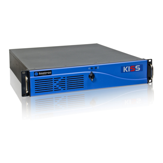
The KISS 2U V2 platform is designed to be installed in 19" racks. It may be also installed as a desktop unit. Versions of the KISS 2U V2 platform: Fig. - Page 16 Fig. 6: KISS 2U V2 platform The KISS 2U V2 platforms are designed to be operated in horizontal position only. When powering on the KISS 2U V2 platform, make sure that the air intake and exhaust openings are not obstructed by objects.
-
Page 17: Front Side
7. Product Description KISS 2U V2 MB_SBC– User's Guide (Version 1.00) 7.1. Front Side The KISS 2U V2 platform is available as a rackmount version. Fig. 7: Front (rackmount version) with the front access panel closed 1 19" bracket with handle... -
Page 18: Power Button
7. Product Description KISS 2U V2_MB_SBC – User's Guide (Version 1.00) The Power button, the USB ports and the integrated 5.25" drive are located on the front side (Fig. 9) of the KISS 2U V2 platform, behind the front access panel. -
Page 19: Led Indicators
KISS 2U V2 MB_SBC– User's Guide (Version 1.00) 7.1.2. LED Indicators The LED indicators (refer to Fig. 9, pos. 5 and Fig. 11) of the KISS 2U V2 are located at the front of the device, behind the front access panel. -
Page 20: Cover Fastening Screw On The Front Side
10.1 “Replacing System Fans”. 7.1.8. Drive Bays Depending on the ordered system configuration, your KISS 2U V2 can be equipped with up to two drive bays (see (Fig. 9, pos. 8 and 9; configuration with an internal HDD): Drive Bay Description (refer to Fig. -
Page 21: Rear Side
The order or the number of the KISS 2U V2 platform interfaces can be different depending on the device configuration. 7.2.1. System Configurations with SBC Card Fig. 13: Rear side of the KISS 2U V2 with an SBC card (shown with a PCI-762 and an AC wide rage PSU) 1 AC inlet connector 5 Air exhaust openings... -
Page 22: System Configuration With Motherboard
12 Mechanical slot 7.2.3. System Configuration with Motherboard and Low Profile Cards Fig. 16: Rear side of the KISS 2U V2 with a KTQ87/Flex (shown as a configuration for low profile expansion cards) 1 AC inlet connector 6 Rear side of the cover with captive knurled screws... - Page 23 SBC card. You can download the relevant board manual for your system configuration from our web site at www.kontron.com by selecting the product name. Refer also to the “KISS 2U V2 Systems - Configuration Guides” on our web site. www.kontron.com...
-
Page 24: Power Supply And On/Off Switch Of The Psu
The power supply is located on the rear side of the KISS 2U V2 platform. The KISS 2U V2 platform is equipped with an AC wide range power supply unit. The corresponding nominal voltage range can be found on the type label on the right side of the system. -
Page 25: Grounding Stud
7.3. Side View On the left and right sides of the device, there are six M4 threaded screw holes, for installing the KISS 2U V2 platform in a 19" industrial cabinet using slide rails [not included; refer also to the chapter 11 “Slide Rails (Option)”.] Fig. -
Page 26: Installed Motherboard / Sbc Card
KISS 2U V2_MB_SBC – User's Guide (Version 1.00) 7.4. Installed Motherboard / SBC Card Depending on the KISS 2U V2 platform configuration ordered, your system may be equipped with a motherboard or an SBC card (Single Board Computer). For KISS 2U V2 versions and system configurations, please refer to the corresponding “KISS 2U V2 Systems - Configuration Guides”... -
Page 27: System Configuration With Motherboard
KISS 2U V2 MB_SBC– User's Guide (Version 1.00) 7.6. System Configuration with Motherboard Please observe that the KISS 2U V2 platform is designed to be operated in horizontal position only. Fig. 22: Example of KISS 2U V2 - Configuration with motherboard... - Page 28 Please observe that the KISS 2U V2 platform is designed to be operated in horizontal position only. Fig. 23: Example of KISS 2U V2 - Configuration with motherboard (shown as config. for low-profile expansion cards) 1 Cover retaining plate on the front side...
-
Page 29: Riser Card And/Or Backplane And Available Bays
KISS 2U V2 MB_SBC– User's Guide (Version 1.00) 7.6.1. Riser Card and/or Backplane and available Bays Depending on the KISS 2U V2 hardware configuration ordered, you can expand your system with full size and/or half size or low-profile additional cards. -
Page 30: Installation And Removal
Ensure that all components are securely installed and that the device cover has been screwed on tightly. 1. Turn the device upside down on a table or desk. 2. Remove the protective film from the rubber feet. 3. Stick the four rubber feet to the underside of the device. www.kontron.com... -
Page 31: Cover
(on the front side) 7 Fixing brackets with knurled screws In order to close the KISS 2U V2 platform chassis, ensure that the cover is properly reinstalled and secured with following screws: the cover fastening screw (Fig. 9, pos. 6) and Fig. 25) on the front side the knurled screws ( Fig. -
Page 32: Accessing Internal Components
Please read information provided by the manufacturer of any expansion cards before installing them or removing them from your system. Installing /Removing Expansion Cards into KISS 2U V2 with SBC/Motherboard (not Low-Profile Cards) 8.3.1.1. To install or remove an expansion card proceed as follows: 1. - Page 33 (Fig. 29). For KISS 2U V2 systems with SBC, unscrew the three screws (Fig. 21, pos. 11) and the four screws on the rear side ( 5. Fig. 13 and Fig. 15, pos. 4). Retain the screws for later use.
- Page 34 Installing /Removing Low-Profile Expansion Cards into 2U V2 with Motherboard 8.3.1.2. For KISS 2U V2 system configuration with motherboard for low-profile expansion cards, is not necessary to remove the card cage, when installing the expansion cards. To install or remove low profile expansion card in system configuration with motherboard proceed as follows: 1.
-
Page 35: Installation In A 19" Industrial Cabinet
Please consider the hints included in the subsection 7.2.4 “Power Supply and ON/OFF Switch of the PSU”. The KISS 2U V2 should be installed in a 19" industrial cabinet using slide rails (PN: 1016-5807). Use for mounting the “Rack Slide Rails Kit for KISS 1U and 2U/4U” (PN: 1051-7200). -
Page 36: Starting Up
To connect the power cable, proceed as follows: 1. The KISS 2U V2 systems with grounding studs marked with an “Earth” symbol (Fig. 19) have to be grounded appropriate “common earth” connection point; (refer to the subsection 7.2.5 “Grounding Stud”, Fig. 19). -
Page 37: Operating System And Hardware Components Drivers
9.2. Operating System and Hardware Components Drivers The KISS 2U V2 system can optionally be supplied with or without a pre- installed operating system. If you have ordered your system with a pre- installed operating system, all drivers are installed, corresponding to the ordered computer configuration (optional hardware components). -
Page 38: Maintenance And Prevention
Hazardous moving parts! Keep away from moving fan blades. The operation of the KISS 2U V2 platform is permitted only with a functional fan slide-in module. Defective components may be replaced only by Kontron original spare parts. part number of the fan slide-in module: 1050-8442 Important instructions! The fan slide-in module is not changeable while the system is powered-on. - Page 39 10. Maintenance and Prevention KISS 2U V2 MB_SBC– User's Guide (Version 1.00) Fig. 32: Fan slide-in module without filtermat holder Fig. 33:Rear view of the fan slide-in module Fig. 34: Fan slide-in module with mounted filter mat holder Fig. 35: Side view of the fan slide-in module Legend for Fig.
-
Page 40: Cleaning The Filter Mat
4 Front access panel 5 Fan slide-in module Fig. 36: Detail with filter mat holder on the fron side of the KISS 2U V2 platform To replace the filter mat, proceed as follows: 1. Open the front access panel (Fig. 36, pos. 4). - Page 41 10. Maintenance and Prevention KISS 2U V2 MB_SBC– User's Guide (Version 1.00) Fig. 37: Detail without filter mat holder on the front side Fig. 38: Filter mat holder without filter mat Fig. 39: Filtermatholder with filter mat Fig. 40: Filter mat Legende für Fig.
-
Page 42: Replacing The Lithium Battery
5. Pay attention to the polarity of the battery. 6. The lithium battery must only be replaced with the same type of battery or with a type of battery recommended by Kontron Europe. 7. Reinstall the removed expansion cards and re-attach the connecting cables. -
Page 43: Slide Rails (Option)
KISS 2U V2 MB_SBC– User's Guide (Version 1.00) 11. Slide Rails (Option) Kontron provides slide rails for installing the KISS 2U V2 in a 19" industrial cabinet. These slide rails can be ordered separately. The KISS 2U V2 systems should be installed into a 19" industrial cabinet with slide rails (PN: 1016- 5807). -
Page 44: Technical Data
The “y” is replaced by a single letter (A through Z) representing the power supply installed into the system. The corresponding “KISS 2U V2 System - Configuration Guides” and the manual of the installed CPU card can be downloaded from our web site at www.kontron.com... -
Page 45: Electrical Specifications
12. Technical Data KISS 2U V2 MB_SBC– User's Guide (Version 1.00) 12.1. Electrical Specifications The corresponding electrical specifications of your KISS 2U V2 platform can be found on the type label. 12.2. Mechanical Specifications Dimensions KISS 2U V2 (Standard Version) Height 2U (88 mm) (3.5”) -
Page 46: Directives And Standards
IEC 60950-1:2005 (Second Edition) + Am 1:2009 Harmonized Standards Generic emission standard for industrial environments (Emission): EN 61000-6-4:2007 Generic standards - Immunity for industrial environments (Immunity): EN 61000-6-2:2005 U.S.A. FCC 47 CFR Part 15, Class A CANADA ICES-003, Class A www.kontron.com... -
Page 47: Standard Interfaces - Pin Assignments
13. Standard Interfaces – Pin Assignments KISS 2U V2 MB_SBC– User's Guide (Version 1.00) 13. Standard Interfaces – Pin Assignments Low-active signals are indicated by a minus sign. 13.1.1. Serial Interface (RS232) Signal Name 9-pin D-SUB Connector (male) (Data Carrier Detect) -
Page 48: Usb Port
13. Standard Interfaces – Pin Assignments KISS 2U V2_MB_SBC – User's Guide (Version 1.00) 13.1.3. USB Port Signal Name 4-pin USB Connector Type A Version 2.0 Data- Data+ www.kontron.com... -
Page 49: Technical Support
Be ready to explain the nature of your problem to the service technician. If you have questions about Kontron Europe or our products and services, you can reach us by the above-mentioned telephone number and on e-mail address or at: www.kontron.com...
Need help?
Do you have a question about the KISS 2U V2 and is the answer not in the manual?
Questions and answers