
Subscribe to Our Youtube Channel
Related Manuals for Kontron KBox A-150-KBL


Summary of Contents for Kontron KBox A-150-KBL
- Page 1 USER GUIDE KBox A-150-KBL Doc. User Guide Rev. 1.1 Doc. ID: 1062-3590 www.kontron.com // 1...
- Page 2 KBox A-150-KBL - User Guide Rev. 1.1 This page has been intentionally left blank www.kontron.com // 2...
- Page 3 In cases of doubt, please contact Kontron. This user guide is protected by copyright. All rights are reserved by Kontron. No part of this document may be reproduced, transmitted, transcribed, stored in a retrieval system, or translated into any language or computer language, in any form or by any means (electronic, mechanical, photocopying, recording, or otherwise), without the express written permission of Kontron.
- Page 4 PHYSICAL OR ENVIRONMENTAL DAMAGE (COLLECTIVELY "HIGH RISK APPLICATIONS"). You understand and agree that your use of Kontron product as a component in High Risk Applications is entirely at your own risk. To minimize the risks associated with your systems and applications, you must provide adequate design and operating safeguards.
- Page 5 If you have any difficulties using this user guide, discover an error, or just want to provide some feedback, contact Kontron support. Detail any errors you find. We will correct the errors or problems as soon as possible and post the revised user guide on our website.
-
Page 6: Symbols
KBox A-150-KBL - User Guide Rev. 1.1 Symbols The following symbols may be used in this user guide DANGER indicates a hazardous situation which, if not avoided, will result in death or serious injury. WARNING indicates a hazardous situation which, if not avoided, could result in death or serious injury. -
Page 7: For Your Safety
Therefore, in the interest of your own safety and of the correct operation of your new Kontron product, you are requested to conform with the following guidelines. -
Page 8: Lithium Battery Precautions
General Instructions on Usage In order to maintain Kontron’s product warranty, this product must not be altered or modified in any way. Changes or modifications to the product, that are not explicitly approved by Kontron and described in this user guide or received from Kontron Support as a special handling instruction, will void your warranty. -
Page 9: Table Of Contents
KBox A-150-KBL - User Guide Rev. 1.1 Table of Contents Symbols ..........................................6 For Your Safety ........................................7 High Voltage Safety Instructions .................................. 7 Special Handling and Unpacking Instruction ............................7 Lithium Battery Precautions ..................................8 General Instructions on Usage ..................................8 Quality and Environmental Management .............................. - Page 10 KBox A-150-KBL - User Guide Rev. 1.1 5.2.1. M.2 Module ......................................27 5.2.2. mPCIe Expansion Cards ..................................27 Accessing Components ................................... 28 6.1. Accessing the 2.5” HDD/SSD Drive Bay ............................. 28 6.2. Opening the System ....................................29 6.3. Installing and Removing M.2 SSD Card ............................32 6.4.
-
Page 11: List Of Tables
Table 8: Mechanical Specification ................................43 Table 9: Environmental Specification ............................... 47 Table 10: KBox A-150-KBL without Wi-Fi - Standards, Certifications and Directives Compliance ........47 Table 11: KBox A-150-KBL with Wi-Fi - Standards, Certifications and Directives Compliance ..........48 Table 12: Power Specification .................................. - Page 12 Figure 21: Keep Out Area for Mounting for KBox A-150-KBL (with no drive bay) ..............36 Figure 22: Keep Out Area for Mounting for KBox A-150-KBL (with heatsink & external 2.5” HDD/SSD drive bay) ..36 Figure 23: Keep Out Area for Mounting for KBox A-150-KBL (with heatsink & no drive bay) ..........36 Figure 24: Keep Out Area for installed dual Wi-Fi Antenna (with external 2.5”...
-
Page 13: 1/ General Safety Instructions For It Equipment
Kontron is exempt from accident liability, this also applies during the warranty period. The product has been built and tested according to the basic safety requirements for low voltage (LVD) applications and has left the manufacturer in safety-related, flawless condition. - Page 14 KBox A-150-KBL - User Guide Rev. 1.1 Additional safety instructions for DC power supply circuits To guarantee safe operation of products with DC power supply voltages larger than 60 volts DC or a power consumption larger than 240 VA, observe that: ...
-
Page 15: Electrostatic Discharge (Esd)
Instructions for Lithium Battery The KBox A-150-KBL is equipped with a Kontron specific battery assembly and is not designed to operate without a battery. If the battery is empty or disconnected, the BIOS settings will be set to the factory defaults. To replace the battery, observe the instructions described in Chapter 14.3.1: Replacing the Lithium Battery. -
Page 16: 2/ Electromagnetic Compatibility (Class B Device)
Kontron is not responsible for any radio television interference caused by unauthorized modifications of this product or the substitution or attachment of connecting cables and devices other than those specified by Kontron. The correction of interference caused by such unauthorized modification, substitution or attachment will be the responsibility of the user. -
Page 17: 3/ Shipment And Unpacking
3.1. Packaging All parts are delivered together in a product specific cardboard package designed to provide adequate protection to absorb shock. Kontron recommends keeping the packaging to store or transport the product. 3.2. Unpacking To unpack the product, perform the following: Remove packaging. -
Page 18: Kontron Parts (Option)
WIBU-Systems security chip. For more information, contact Kontron Support. 3.6. Type Label and Product Identification The KBox A-150-KBL is part of Kontron’s DIN rail embedded Box PC. Kontron’s A-Series is intended for control cabinet applications. Table 3: Product Identification System... -
Page 19: 4/ System Overview
The KBox A-150-KBL is a flexible fanless industrial grade DIN rail embedded box PC designed for use in performance demanding applications requiring flexible DIN rail mounting positions in limited space, 24/7 continuous operation and longtime industrial employment. -
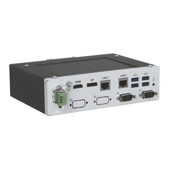
Page 20: Front Panel Views
Front Panel Views The front panel includes all I/O connectors. The protective earth stud bolt’s position varies depending on whether the KBox A-150-KBL includes an external 2.5” HDD/SSD drive bay. Figure 3: Front Panel (with external 2.5” HDD/SSD drive bay) -
Page 21: Dc Input Power Connector
KBox A-150-KBL - User Guide Rev. 1.1 4.1.1. DC Input Power Connector The 3-pin DC input power connector (PSC 1,5/ 3-M) connects to the appropriate DC main power supply using the supplied DC mating connector (PSC 1,5/ 3-F) , see Figure 3 and Figure 4, pos. 1. For information on how to wire the DC mating power connector, see Chapter 8.3: Wiring the DC Mating Power Connector. -
Page 22: Rear View
KBox A-150-KBL - User Guide Rev. 1.1 4.2. Rear View Figure 5: Rear View DIN rail clamp 4.3. Top View and Bottom View Figure 6: Top View and Bottom View DIN rail clamp Heatsink plate on top side 4x Mounting holes for the heatsink... -
Page 23: Side Views
KBox A-150-KBL - User Guide Rev. 1.1 4.4. Side Views The 2.5” HDD/SSD drive bay is located on the left side. The height of the KBox A-150-KBL’s chassis increases with the external 2.5” HDD/SSD drive bay option: 58 mm high with drive bay ... -
Page 24: Internal Components
KBox A-150-KBL - User Guide Rev. 1.1 4.5. Internal Components Figure 9: Internal Components Main chassis 1x mPCIe slot with card 2.5” HDD/SSD drive bay 1x M.2 socket with module SATA connector Lithium battery 2x Screw holes for2x bottom head (M3x5) screws... -
Page 25: Main On-Board Components
KBox A-150-KBL - User Guide Rev. 1.1 4.5.1. Main On-board Components Figure 10: Main On-board Connectors Lithium battery power input connector 10 M.2 key B socket USB power selection jumper 11 Serial port 1 connector DIMM1 12 Power on switch front panel pin header... -
Page 26: 5/ System Expansion
Depending on the ordered system configuration, the KBox A-150-KBL can be extended externally and internally with: 2.5” HDD/SSD drive bay (external) ... -
Page 27: Internal Expansion
KBox A-150-KBL - User Guide Rev. 1.1 5.2. Internal Expansion The KBox A-150-KBL supports one M.2 (2242) SSD module and one mPCIe (full-size) expansion card. Kontron recommends the use of Kontron reference M.2 modules and mPCIe cards. Protection label The KBox A-150-KBL is factory configured to meet customer requirements and then sealed with a protection label. -
Page 28: 6/ Accessing Components
Opening the KBox A-150-KBL invalidates the warranty and may cause damage to internal components. Before opening the KBox A-150-KBL, the product must be switched off using the power-on switch, and disconnect all peripheral devices. Disconnect the product from the AC mains power supply by removing the power cable from the DC power supply or the mains power socket. -
Page 29: Opening The System
Opening the KBox A-150-KBL invalidates the warranty and may cause damage to internal components. Before opening the KBox A-150-KBL, the product must be switched off using the power-on switch, and disconnect all peripheral devices. Disconnect the product from the AC mains power supply by removing the power cable from the DC power supply or the mains power socket. -
Page 30: Figure 12: Sbc Fastening Screws
KBox A-150-KBL - User Guide Rev. 1.1 Figure 12: SBC Fastening Screws 2x Bottom head torx (M3x5) screws 2x Screws fasten the front panel to SBC to form a Front panel-SBC assembly that slides in/out of the chassis. Do not remove or loosen the screws! Do not remove or loosen the two screws (Figure 12, pos. -
Page 31: Figure 14: Removing The Front Panel- Sbc Assembly
KBox A-150-KBL - User Guide Rev. 1.1 Carefully slide the front panel-SBC assembly out of the main chassis while taking care not to damage the SBC and internal components. When removing the front panel-SBC assembly ensure that internal cables do not catch on internal components. -
Page 32: Installing And Removing M.2 Ssd Card
6.3. Installing and Removing M.2 SSD Card Protection label The KBox A-150-KBL is factory configured to meet customer requirements and then sealed with a protection label. Opening the KBox A-150-KBL invalidates the warranty and may cause damage to internal components. -
Page 33: Installing And Removing Mpcie Expansion Cards
6.4. Installing and Removing mPCIe Expansion Cards Protection label The KBox A-150-KBL is factory configured to meet customer requirements and then sealed with a protection label. Opening the KBox A-150-KBL invalidates the warranty and may cause damage to internal components. -
Page 34: 7/ Thermal Considerations
KBox A-150-KBL - User Guide Rev. 1.1 7/ Thermal Considerations The KBox A-150-KBL is fanless and passively cooled using a heatsink plate or optional heatsink. The heatsink plate and optional heatsink absorb the heat produced by the internal components and transfers the heat away from the internal components by dissipating the heat into the ambient environment. -
Page 35: 8/ Installation Instructions
8.1. DIN Rail Mounting The KBox A-150-KBL is mounted on a DIN Rail in a control cabinet using a DIN rail clamp assembled on either the: Top side of the chassis ... -
Page 36: Control Cabinet Mounting
Figure 21: Keep Out Area for Mounting for KBox A-150-KBL (with no drive bay) 8.5 mm Up to 50 mm cable clearance Figure 22: Keep Out Area for Mounting for KBox A-150-KBL (with heatsink & external 2.5” HDD/SSD drive bay) 26.7 mm Up to 50 mm cable clearance 100 mm Figure 23: Keep Out Area for Mounting for KBox A-150-KBL (with heatsink &... -
Page 37: Wiring The Dc Mating Power Connector
KBox A-150-KBL - User Guide Rev. 1.1 For the KBox A-150-KBL with Wi-Fi, the front panel keep out area depends on the implemented dual Wi-Fi antennas and the orientation of the Wi-Fi antennas. Figure 24: Keep Out Area for installed dual Wi-Fi Antenna (with external 2.5” HDD/SSD drive bay) - Page 38 KBox A-150-KBL - User Guide Rev. 1.1 To wire the supplied 3-pin Phoenix DC mating power connector (PSC 1,5/ 3-F), perform the following: Cut three (1 mm ) AWG18 isolated wires to the required length and strip each end 5 mm – 7 mm.
-
Page 39: 9/ Switching On
Support I/O cables and power wiring to minimize strain on the connectors. Before switching on the KBox A-150-KBL for the first time, wire the supplied DC mating power connector (PSC 1,5/3-F) to the DC power supply as described in , see Chapter 8.3: Wiring the DC Mating Power Connector. -
Page 40: Switching Off
9.3. Switching On To switch on while the KBox A-150-KBL is connected to the DC power supply, perform the following: Press the Power-on switch, see Figure 3 and Figure 4, pos. 7. The system switches on. -
Page 41: 10/ Technical Data
KBox A-150-KBL - User Guide Rev. 1.1 Technical Data 10.1. Block Diagram Figure 26: Block Diagram KBox A-150-KBL 2x DDR4 2133 Intel ® Core ™ I5-7300U SODIMM Sockets Up to 32 GB max. Audio 1x DisplayPort Header Audio 1x HDMI... -
Page 42: Technical Specification
24 VDC nominal input voltage IP Protection Class IP 40 Operating System (OS) Windows 10 IoT Enterprise 2016 LTSB Linux Ubuntu 16.04LTS BIOS AMI uEFI BIOS, Aptio V5 Only possible for KBox A-150-KBL variants with externally 2.5” HDD/SSD drive bay www.kontron.com // 42... -
Page 43: Mechanical Specification
For detailed mechanical information, refer to the outline dimensions diagrams in this chapter showing the main external mechanical dimensions. The following outline dimension drawings show the features for the KBox A-150-KBL with an external 2.5” HDD/SSD drive bay. Figure 27: Front Panel Dimensions with External 2.5” HDD/SSD Drive Bay (mm) Figure 28: Rear Side Dimensions with External 2.5”... -
Page 44: Figure 29: Top Side Dimensions With External 2.5" Hdd/Ssd Drive Bay (Mm)
Figure 30: Side View Dimensions with External 2.5” HDD/SSD Drive Bay (mm) 94.8 135.25 The following outline dimension drawings show the features for the KBox A-150-KBL without a drive bay. Figure 31: Front Panel Dimensions without Drive Bay (mm) www.kontron.com... -
Page 45: Figure 32: Rear Side Dimensions Without Drive Bay (Mm)
KBox A-150-KBL - User Guide Rev. 1.1 Figure 32: Rear Side Dimensions without Drive Bay (mm) 90.5 Figure 33: Top Side Dimensions without Drive Bay (mm) 130.25 Figure 34: Side View Dimensions without Drive Bay (mm) 130.25 www.kontron.com // 45... -
Page 46: Figure 35: Mechanical Diagram Heatsink
KBox A-150-KBL - User Guide Rev. 1.1 10.3.1.1. Mechanical Diagrams Heatsink The following outline dimension drawings show the features of the optional heatsink with DIN rail mounting holes. Figure 35: Mechanical Diagram Heatsink 32.5 30° 7.62 32.5 1.5 ±0.1 32.5 32.5... -
Page 47: Environmental Specification
The KBox A-150-KBL without Wi-Fi, complies with the European Council Directive (93/68/EEC) and the approximation of the laws of the member states, see Table 10. The KBox A-150-KBL with Wi-Fi, complies with the Radio Equipment Directive (RED) (2014/53/EU) and the approximation of the laws of the member states, see Table 11. -
Page 48: Table 11: Kbox A-150-Kbl With Wi-Fi - Standards, Certifications And Directives Compliance
Compliant with the Restriction of Hazardous Substances (RoHS) 2011/65/EU directive or the late status thereof, to reduce hazardous substances in electrical and electronic equipment Table 11: KBox A-150-KBL with Wi-Fi - Standards, Certifications and Directives Compliance RED Directive 2014/53/EU Draft ETSI EMC standard for radio equipment and services;... - Page 49 KBox A-150-KBL - User Guide Rev. 1.1 FCC 47 CFR Part 15 Complies with part 15 FCC rules and regulations of title 47 of the CFR rules for class B (Class B) products; under which an unintentional radiator may be operated, administrated and other conditions relating to the marketing of part 15 devices.
-
Page 50: Power Specification
Power Specification The KBox A-150-KBL’s must be supplied with a nominal input voltage of 24 VDC from an external power supply that connects to the front panel DC input power connector using the supplied DC mating power connector (PSC 1,5/ 3-F) wired as described in Chapter 8.3: Wiring the DC Mating Power Connector. -
Page 51: Power Consumption
10.6.2. Power Consumption The total power consumption depends on factors such as the capacity of the SBC, external interfaces and system expansion. Use an appropriate PSU that is able to supply the power required by all KBox A-150-KBL configured components. -
Page 52: 11/ Connector Pin Assignments
KBox A-150-KBL - User Guide Rev. 1.1 11/ Connector Pin Assignments 11.1. Front Panel Connector Pin Assignments 11.1.1. DC Input Power Connector (- +) 3-Pin Phoenix PSC 1.5/3-M Power Connector Signal Name GND (-) Functional Earth VCC (+) 11.1.2. HDMI Connector (HDMI) -
Page 53: Gbe Lan Rj45 Connectors (Lan1, Lan2)
KBox A-150-KBL - User Guide Rev. 1.1 11.1.4. GbE LAN RJ45 Connectors (LAN1, LAN2) RJ45 (female) Signal Name Signal Name MDI0+ MDI2- MDI0- MDI1- MDI1+ MDI3+ MDI2+ MDI3- Left LED: Speed Right LED: Activity/Link 10 Mbit NO LAN connectivity Green... -
Page 54: Sbc On-Board Connector And Jumper Pin Assignments
KBox A-150-KBL - User Guide Rev. 1.1 11.2. SBC On-board Connector and Jumper Pin Assignments Observe the procedures and instructions within this user guide when handling internal component. 11.2.1. Battery Power Input Connector Connector for Kontron’s RTC battery assembly. Signal Name +VBAT 11.2.2. -
Page 55: Serial Port 1 And Serial Port 2 Connector
KBox A-150-KBL - User Guide Rev. 1.1 11.2.5. Serial Port 1 and Serial Port 2 Connector Both serial ports are RS232, RS422 and RS485 configurable in the BIOS setup menu Advanced>Super IO configuration>Serial port # configuration>Serial port # Type> RS232, RS422, RS485. -
Page 56: Left Channel 3W Audio Amp Output Connector
KBox A-150-KBL - User Guide Rev. 1.1 11.2.8. Left Channel 3W Audio AMP Output Connector Speaker output left. Signal Name Speaker+ Speaker- 11.2.9. Right Channel 3W Audio AMP Output Connector Speaker output right. Signal Name Speaker+ Speaker- 11.2.10. Power-on Switch Pin Header Connects to the front panel’s Power-on switch. -
Page 57: 12/ Bios
KBox A-150-KBL - User Guide Rev. 1.1 BIOS The KBox A-150-KBL uses the AMI uEFI BIOS supported by the SBC and based on the Unified Extensible Firmware Interface (uEFI) specification and the Intel® Platform Innovation Framework for EFI. The AMI uEFI BIOS preferences are preset and do not require further adjustment for operation. -
Page 58: Setup Menus
KBox A-150-KBL - User Guide Rev. 1.1 12.2. Setup Menus The Setup utility features menus listed in the selection bar at the top of the screen are: Main Advanced Power Boot Security Save & Exit The current active menu and active BIOS Setup item are highlighted in white. -
Page 59: Advanced Setup Menu
KBox A-150-KBL - User Guide Rev. 1.1 12.2.2. Advanced Setup Menu Figure 37: Advanced Setup Menu Example Aptio Setup Utility – Copyright (C) 2018 American Megatrends, Inc. Main Advanced Power Boot Security Save & Exit Onboard LAN1 Controller [Enabled] Onboard LAN2 Controller... - Page 60 KBox A-150-KBL - User Guide Rev. 1.1 Sub-screen Additional Sub-screens with Description Super IO Serial Port 1 Change [Auto; IO=3F8h; IRQ=4; Configuration Configuration Settings IO=3F8h; IRQ=3, 4, 5, 6, 7, 9, 10, 11, 12; (continued) (continued) IO=2F8h; IRQ=3, 4, 5, 6, 7, 9, 10, 11, 12;...
- Page 61 KBox A-150-KBL - User Guide Rev. 1.1 Sub-screen Additional Sub-screens with Description TPM Computing Security Device Support [Enabled, Disabled] Enabled is the customer setting Active PCR Banks (*) Read only field SHA-1,SHA256 Available PCR Banks (*) Read only field SHA-1,SHA256...
- Page 62 KBox A-150-KBL - User Guide Rev. 1.1 Sub-screen Additional Sub-screens with Description H/W Monitor Read only text CPU temperature, memory temperature, System temperature, CPU fan speed, +VCORE, +Vin, +3 VCC, +3 VSB, +VBAT, +5 VA, +3 VA Smart FAN Configuration...
-
Page 63: Power Setup Menu
KBox A-150-KBL - User Guide Rev. 1.1 12.2.3. Power Setup Menu Figure 38: Power Setup Menu Example Aptio Setup Utility – Copyright (C) 2018 American Megatrends, Inc. Power Main Advanced Boot Security Save & Exit Power Configuration ACPI Sleep State... -
Page 64: Boot Setup Menu
KBox A-150-KBL - User Guide Rev. 1.1 12.2.4. Boot Setup Menu Figure 39: Boot Setup Menu Example Aptio Setup Utility – Copyright (C) 2018 American Megatrends, Inc. Boot Main Advanced Power Security Save & Exit Boot Configuration Full Screen LOGO Display... -
Page 65: Security Setup Menu
KBox A-150-KBL - User Guide Rev. 1.1 12.2.5. Security Setup Menu Figure 40: Security Setup Menu Example Aptio Setup Utility – Copyright (C) 2018 American Megatrends, Inc. Security Main Advanced Power Boot Save & Exit Password Description If ONLY the Administrator’s password is set, then... - Page 66 KBox A-150-KBL - User Guide Rev. 1.1 Function Description Secure Boot Menu Key Managaement Provision Factory [Enabled, Disabled] (continued) Defaults Install Factory Default keys Enroll Efi Image Save all Secure Boot Read only field variables Secure Boot Variable Size Key#...
-
Page 67: Save And Exit Set Up Menu
KBox A-150-KBL - User Guide Rev. 1.1 12.2.6. Save and Exit Set up Menu Figure 41: Save and Exit Set up Menu Example Aptio Setup Utility – Copyright (C) 2018 American Megatrends, Inc. Main Advanced Power Boot Security Save & Exit... -
Page 68: 13/ Technical Support
RMA number. The buyer accepts responsibility for all freight charges for the return of goods to Kontron's designated facility. Kontron will pay the return freight charges back to the buyer's location in the event that the equipment is repaired or replaced within the stipulated warranty period. Follow these steps before returning any product to Kontron. -
Page 69: 14/ Storage, Transportation And Maintenance
The KBox A-150-KBL is equipped with a Kontron specific battery assembly that may need to be replaced during the lifetime of the product. The KBox A-150-KBL is not designed to operate without a battery. If the battery is empty or disconnected, the BIOS settings will be set to the factory defaults. -
Page 70: Figure 43: Lithium Battery Power Input Connector
The lithium battery type must be UL recognized. The KBox A-150-KBL is not designed to operate without a battery. If the battery is empty or disconnected, the BIOS settings will be set to the factory defaults. -
Page 71: 15/ Warranty
Limitation/Exemption from Warranty Obligation In general, Kontron shall not be required to honor the warranty, even during the warranty period, and shall be exempted from the statutory accident liability obligations in the event of damage caused to the product due to failure to observe the following: ... -
Page 72: Appendix A: List Of Acronyms
KBox A-150-KBL - User Guide Rev. 1.1 Appendix A: List of Acronyms Table 20: List of Acronyms (Example) Alternating Current PCIe PCI-Express ACPI Advanced Configuration Control Interface Power Supply Unit Central Processing Unit Read Access Memory Direct Current RoHS Restriction of the use of certain... -
Page 73: About Kontron
KBox A-150-KBL – User Guide Rev. 1.1 About Kontron Kontron is a global leader in embedded computing technology (ECT). As a part of technology group S&T, Kontron offers a combined portfolio of secure hardware, middleware and services for Internet of Things (IoT) and Industry 4.0 applications.
Need help?
Do you have a question about the KBox A-150-KBL and is the answer not in the manual?
Questions and answers