Sign In
Upload
Manuals
Brands
Kontron Manuals
Industrial PC
KBox B-202-RPL
Kontron KBox B-202-RPL Manuals
Manuals and User Guides for Kontron KBox B-202-RPL. We have
1
Kontron KBox B-202-RPL manual available for free PDF download: User Manual
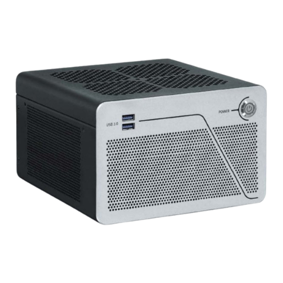
Kontron KBox B-202-RPL User Manual (95 pages)
Brand:
Kontron
| Category:
Industrial PC
| Size: 5 MB
Table of Contents
Symbols
6
For Your Safety
7
High Voltage Safety Instructions
7
Special Handling and Unpacking Instruction
7
Lithium Battery Precautions
8
General Instructions on Usage
8
Quality and Environmental Management
8
Disposal and Recycling
8
WEEE Compliance
8
Table of Contents
9
List of Tables
12
List of Figures
12
1 / Introduction
14
Figure 1: Kbox B-202-RPL
14
2 / General Safety Instructions
16
Instructions Générales de Sécurité
17
Electrostatic Discharge (ESD) Precautions
18
Grounding Methods
18
Instructions for the Lithium Battery
19
3 / Shipment and Unpacking
21
Packaging
21
Unpacking
21
Scope of Delivery
21
Accessories
21
Table 1: Scope of Delivery
21
Table 2: Accessories
21
Product Identification Type Label
22
Figure 2: Type Labels Examples
22
4 / Product Features
23
Front Panel
23
Power Button
23
USB 3.2 Gen 1 Ports
23
Figure 3: Front Panel
23
Rear Panel
24
Figure 4: Rear Panel (Smart Performance)
24
Figure 5: Rear Panel (Smart Storage)
25
USB 3.2 Gen 2/Gen1 Ports
26
USB-C 3.2 Gen 2
26
USB 2.0 Ports
26
Display Port (DP)
26
LAN Ports
27
Audio (Line-In, Line-Out)
27
COM Port
27
Wi-Fi Antenna (Option)
27
GPIO (Option)
27
DC in (Default)
28
DC in 24 VDC (Option)
28
DC in (240 W) (Option-Smart Performance Line Only)
28
AC-IN (Option-Smart Storage Line Only)
29
Potential Equalization Stud
29
Left and Right Side
30
Figure 6: Left Side and Right Side
30
Top Cover and Bottom Side
31
Figure 7: Top Cover
31
Figure 8: Bottom Side
31
5 / System Expansion
32
Before Expanding
32
Overview
32
Table 3: Overview
32
Drive Bay
33
Internal Expansion
33
Table 4: Drive Bay Options
33
Table 5: Internal Expansion Options
33
Figure 9: Drive Bay Options
33
Pcie Slots
34
Storage Bay (Smart Storage Only)
34
Table 6: Pcie Expansion Card Slot Options
34
Figure 10: Pcie Expansion Slots
34
Reference Expansion Devices
35
Table 7: Storage Bay Options
35
Figure 11: Storage Bay with Dual Removable 2.5" Ssds
35
6 / Thermal Management
36
Active Cooling
36
Figure 12: Ventilation Openings (Intake)
36
Figure 13: Ventilation Openings (Output)
36
Mount Orientation
37
Minimum Clearance (Keep out Area)
37
Third Party Components
37
7 / Assembly
38
Before Assembling
38
Opening the Product
38
Installing and Removing an M.2 Module
39
Opening the Drive Bay
40
Installing and Removing 2.5" SSD Drive
41
Figure 14: External Drive Bay with 2.5" SSD Drive
41
Installing and Removing 2.5" SSD Dual M.2 RAID Module
42
Figure 15: 2.5" SSD Dual RAID M.2 Module
43
Figure 16: Drive Bay with 2.5" SSD Dual M.2 RAID Module
43
Connecting the Wi-Fi Antenna (Option)
45
Opening the Expansion Door
45
Installing and Removing Pcie Expansion Cards
46
Figure 17: Removing Expansion Door
46
Storage Bay
47
Installing and Removing Storage Bay Drives
47
Figure 18: Storage Bay with Dual Removable 2.5" SSD Drives
47
Figure 19: Storage Bay Tray
48
8 / Installation
49
Before Installing
49
Chassis Feet
50
Figure 20: Chassis Feet
50
Mounting Brackets (Option)
51
Figure 21: Mounting Bracket
51
Mounting Brackets Desktop
52
Figure 22: Keep out Areas - with Top Cover Facing the Mount Surface
52
Figure 23: Keep out Areas - with Bottom Side Facing the Mount Surface
52
Figure 24: Mounting Brackets on a Desktop/Mount Surface
53
Figure 25: Mounting Bracket- Underneath a Desktop/Mount Surface
53
Mounting on a Wall
54
Figure 26: Mounting Brackets Wall Mount Options with Top Cover Facing Outwards
54
Figure 27: Mounting Brackets Wall Mount Options with Top Cover Facing the Mounting Surface
54
9 / Starting up
55
Before Starting
55
Connecting the External AC/DC (150 W) Power Supply
56
Figure 28: DC in Power Connector
56
Figure 29: External AC/DC (150 W) Power Supply
56
Connecting the AC/DC (240 W) Power Supply (Option)
57
Figure 30: DC in 10-Pin Connector
57
Figure 31: External AC/DC (150 W) Power Supply
57
Connecting to a 24 VDC Power Supply (Option)
58
Wiring the 3-Pin Mating Power Connector
58
Figure 32: DC in 3-Pin Power Connector and 3-Pin Mating Power Connector
58
Connecting to a DC Power Supply
59
Connecting to AC Mains (Option)
59
Figure 33: AC-IN 3-Pin Connector
59
Switching On/Off
60
Forced Shutdown
60
Operating System (OS) and Hardware Component Drivers
60
10 / Bios
61
Starting the Uefi BIOS
61
BIOS Setup Menus
61
BIOS Navigation
62
BIOS Update
62
Updating the BIOS
62
Table 8: Navigation Hot Keys Available in the Legend Bar
62
Recover BIOS
63
Figure 34: BIOS FTP Server Example
63
11 / Raid
64
Drive Bay RAID Array
64
Drive Bay RAID Configuration
64
Table 9: Drive Bay RAID
64
Figure 35: 2.5" SSD Dual RAID M.2 Module Settings
64
Drive Bay RAID Software
65
Table 10: RAID Module Jumper Settings
65
Table 11: S.M.A.R.T. Information Memory Attributes Examples
66
Table 12: Notifications Examples
66
Table 13: Event List Examples
66
Storage Bay RAID Array
67
Storage Bay RAID Configuration
67
Table 14: Storage Bay RAID Array
67
Figure 36: Storage RAID (External)
67
Internal RAID Array
68
Internal RAID Array Configuration
68
Table 15: Internal RAID
68
12 / Product Specification
69
Block Diagrams
69
Figure 37: Block Diagram of Kbox B-202-RPL Smart Performance and Smart Storage
69
Hardware Specification
71
Table 16: Hardware Specification
71
Table 17: Storage Specification
72
Software Specification
73
Power Specification
73
AC/DC (150 W) Power Supply
73
Table 18: External Expansion Slots
73
Table 19: Software Specification
73
Table 20: AC/DC 150 W Power Supply Electrical Specification
73
AC/DC (240 W) Power Supply (Option)
74
VDC Connector (Option)
74
Table 21: AC/DC 240 W Power Supply Electrical Specification
74
Table 22: 24 VDC Connector Electrical Specification
74
AC-IN (Option)
75
Power Protection
75
Table 23: AC-IN Power Supply Electrical Specification (Option)
75
Power Consumption
76
Potential Equalization
76
Table 24: Power Supply Protection Features (AC/DC 150 W, AC/DC 240 W)
76
Table 25: Power Consumption Estimation
76
Environmental Specification
77
Mechanical Specification
77
Dimension Diagrams
77
Table 26: Environmental Specification
77
Table 27: Mechanical Specifications
77
Figure 38: Dimensions Front Panel
77
Figure 39: Dimensions Rear Panel
77
Figure 40: Dimensions Right Side
78
Figure 41: Dimensions Left Side
78
Figure 42: Dimension Top Cover
78
Figure 43: Dimensions Bottom Side
78
Figure 44: Dimensions with Mounting Brackets
79
Compliance
80
Table 28: Compliance
80
Table 29: International Compliance
81
13 / Connectors and Leds
83
DC in 12 VDC, Power Connector (Default)
83
DC in 10-Pin Power Connector (Option- Smart Performance Only)
83
Table 30: DC in 12 VDC Power Jack Pin Assignment
83
Table 31: DC IN, 240 W Power Connector Pin Assignment
83
DC in 24 VDC (Option)
84
AC-IN Power Connector Pin Assignment (Option)
84
Table 32: 3-Pin Power Connector Pin Assignment
84
USB 3.2 Gen2/Gen1 Port Pin Assignment
85
USB-C 3.2 Gen2 Pin Assignment
85
USB 2.0 Port Pin Assignment
85
Table 33: USB 3.1 Gen 2/1 /Type-A) Pin Assignment
85
Table 34: USB 3.1 Port Pin Assignment
85
Table 35: USB 2.0 Port Pin Assignment
85
Display Port (DP) V1.4A Pin Assignment
86
LAN 2.5 Gbe/1Gbe Connector Pin Assignment
86
Table 36: Display Port (DP) Connector Pin Assignment
86
Table 37: LAN (Gbe) Connector Pin Assignment
86
COM1 Port (RS232) Pin Assignment
87
Audio Line-Out and Line-In Connector Pin Assignment
87
Table 38: Serial Interface COM Port (RS232) Connector Pin Assignment
87
Table 39: Audio Line-OUT Audio Line-IN Pin Assignment
87
Jumpers
88
Recovery BIOS Jumper
88
Table 40: Recover BIOS Jumper
88
Figure 45: Recover BIOS Jumper
88
14 / Maintenance
89
Cleaning
89
Replacing the Lithium Battery
89
Figure 46: Vertical Battery Holder
89
15 / Storage and Transportation
91
Storage
91
Transportation
91
16 / Technical Support
92
Returning Defective Merchandise
92
Warranty
93
Limitation/Exemption from Warranty Obligation
93
List of Acronyms
94
Table 41: List of Acronyms
94
About Kontron
95
Advertisement
Advertisement
Related Products
Kontron KBox B-201
Kontron KBox B-201-RPL
Kontron KBox B-203-RPL
Kontron KBox B-204-RPL
Kontron KBox Series
Kontron KBox A-103
Kontron KBox M-200 Series
Kontron KBox A-150-HSW
Kontron KBox A-150-KBL
Kontron KBox A-151-TGL
Kontron Categories
Computer Hardware
Motherboard
Server
Industrial PC
Desktop
More Kontron Manuals
Login
Sign In
OR
Sign in with Facebook
Sign in with Google
Upload manual
Upload from disk
Upload from URL