
Related Manuals for Kontron KBox B-204-RPL


Summary of Contents for Kontron KBox B-204-RPL
- Page 1 User Guide KBox B-204-RPL Preliminary User Guide Rev. 0.2 Doc. ID 1075-0134 www.kontron.com...
- Page 2 KBox B-204-RPL – Preliminary User Guide Rev. 0.2 This page has been intentionally left blank www.kontron.com...
- Page 3 In cases of doubt, please contact Kontron. This user guide is protected by copyright. All rights are reserved by Kontron. No part of this document may be reproduced, transmitted, transcribed, stored in a retrieval system, or translated into any language or computer language, in any form or by any means (electronic, mechanical, photocopying, recording, or otherwise), without the express written permission of Kontron.
-
Page 4: Intended Use
(collectively, “high risk applications”). You understand and agree that your use of Kontron devices as a component in High Risk Applications is entirely at your risk. To minimize the risks associated with your products and applications, you should provide adequate design and operating safeguards. -
Page 5: Revision History
Kontron sells products worldwide and declares regional General Terms & Conditions of Sale, and Purchase Order Terms & Conditions. Visit www.kontron.com/terms-and-conditions. For contact information, refer to the corporate offices contact information on the last page of this user guide or visit... -
Page 6: Symbols
KBox B-204-RPL – Preliminary User Guide Rev. 0.2 Symbols The following symbols may be used in this user guide DANGER indicates a hazardous situation which, if not avoided, will result in death or serious injury. WARNING indicates a hazardous situation which, if not avoided, could result in death or serious injury. - Page 7 KBox B-204-RPL – Preliminary User Guide Rev. 0.2 Security This symbol indicates general information and guidelines regarding security/cyber security to ensure installation, operation, maintenance and disposal of the product meet the required guidelines within the user’s end environment. This symbol indicates general information about the product and the user guide.
-
Page 8: For Your Safety
Therefore, in the interest of your own safety and of the correct operation of your new Kontron product, you are requested to conform with the following guidelines. -
Page 9: Lithium Battery Precautions
General Instructions on Usage In order to maintain Kontron’s product warranty, this product must not be altered or modified in any way. Changes or modifications to the product, that are not explicitly approved by Kontron and described in this user guide or received from Kontron Support as a special handling instruction, will void your warranty. -
Page 10: Table Of Contents
KBox B-204-RPL – Preliminary User Guide Rev. 0.2 Table of Contents Revision History ................................5 Symbols ..................................6 For Your Safety ................................8 High Voltage Safety Instructions ........................... 8 Special Handling and Unpacking Instruction ......................8 Lithium Battery Precautions ..........................9 General Instructions on Usage ............................ - Page 11 KBox B-204-RPL – Preliminary User Guide Rev. 0.2 7.3.1. Installing and Removing PCIe Cards ....................44 7.4. Installing or Removing a Removable 2.5” SSD....................45 Installation ................................47 8.1. Before Installing ............................47 8.2. Chassis Feet ..............................48 8.3. Wall Mount ..............................48 Starting Up................................
-
Page 12: List Of Tables
KBox B-204-RPL – Preliminary User Guide Rev. 0.2 14.2. Replacing Lithium Battery .......................... 76 14.3. BIOS Recovery Jumper..........................77 15/ Storage and Transportation ..........................78 15.1. Storage ............................... 78 15.2. Transportation ............................78 16/ Technical Support ..............................79 16.1. Returning Defective Merchandise ......................79 17/ Warranty ................................ -
Page 13: List Of Figures
KBox B-204-RPL – Preliminary User Guide Rev. 0.2 Table 33: Audio (Line-In & Line-Out) Pin Assignment ....................74 Table 34: COM (RS232) Connector Pin Assignment ....................75 Table 35: Antenna Wi-Fi/BT® ............................75 Table 36: Battery Header ............................77 Table 37: CR2032 Lithium Battery with Connector ..................... 77 Table 38: Statement of Memory Volatility (Example) .................... -
Page 14: 1/ Introduction
Display Ports enable the connection of up to four simultaneous displays. The product is power by an AC/DC (150 W or 240 W) power supply provided by Kontron in the delivery, an optional 24 VDC power variant for direct connection to an external 24 VDC power supply or an optional AC IN power connection. - Page 15 KBox B-204-RPL – Preliminary User Guide Rev. 0.2 Rear Interfaces: 4x DP 3x USB 3.2 Gen 2 1x USB-C 3.2 Gen 2 4x USB 2.0 1x 2.5 GbE 1x 1 GbE 1x Audio 1x COM RS232 (option) 1x Breakout panel (COM RS232 option)
-
Page 16: 2/ General Safety Instructions
Only connect the product to an external power supply providing the voltage type (AC or DC) and the input power (max. current) specified on the Kontron Product Label and meeting the requirements of the Limited Power Source (LPS) and Power Source (PS2) of UL/IEC 62368-1 . -
Page 17: Additional Safety Instructions For Dc Power Supply Circuits
Le non-respect des consignes de sécurité générales suivantes peut entraîner des blessures pour l'utilisateur et/ou des dommages pour le produit. En cas de non-respect des consignes, Kontron Europe est exonéré de la responsabilité en cas d'accident, ceci s'applique également pendant la période de garantie. -
Page 18: Electrostatic Discharge (Esd)
Seuls les accessoires d'origine approuvés par Kontron Europe peuvent être utilisés. Veuillez noter que la sécurité des opérations n'est plus possible lorsque l'une des conditions suivantes s'applique. -
Page 19: Grounding Methods
KBox B-204-RPL – Preliminary User Guide Rev. 0.2 2.4. Grounding Methods The following measures help to avoid electrostatic damages to the device: Cover workstations with approved antistatic material. Always wear a wrist strap connected to the workplace, as well as properly grounded tools and equipment. -
Page 20: 3/ Shipment And Unpacking
KBox B-204-RPL – Preliminary User Guide Rev. 0.2 3/ Shipment and Unpacking 3.1. Packaging The KBox B-204-RPL is packaged together with all parts, in a product specific cardboard package designed to provide adequate protection and absorb shock. 3.2. Unpacking To unpack the product perform the following: 1. -
Page 21: Accessories And Spare Parts
KBox B-204-RPL – Preliminary User Guide Rev. 0.2 3.4. Accessories and Spare Parts Table 2: List of Accessories and Spare Parts Part Order Information Description Manufacturer: Kontron Phoenix 3-pin power connector (PSC 1.5/3-F) Article Number: 0-0062-3268 Manufacturer: Kontron External AC/DC (150 W) power supply... -
Page 22: Type Label And Product Identification
KBox B-204-RPL – Preliminary User Guide Rev. 0.2 3.5. Type Label and Product Identification The type label contains specific product identification information and KBox B-204 RPL technical information. Figure 2: Type Label Example 7.5 A 1. Product family 6. Production date 2. -
Page 23: 4/ Product Features
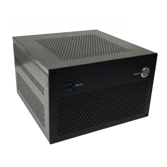
4.1.2. USB 3.2 Gen 1 Ports (USB 3.0) The two front panel USB ports are USB 3.2 Gen 1 Type-A ports. Kontron recommends the use of USB 3.2 Gen 1 compliant devices or cables only. The use of devices and cables that violate the USB 3.2 Gen 1 specification may cause conditions such as non-recognition of the device or read/write errors. -
Page 24: Rear Panel
KBox B-204-RPL – Preliminary User Guide Rev. 0.2 4.2. Rear Panel The rear panel features the main I/O interfaces, one power connector (12 VDC (150 W or 240 W), 24 VDC or 240 VAC), two RP-SMA antenna connectors (option), potential equalization stud, Kensington lock, two top cover fastening screws to secure the top cover and two expansion bays. -
Page 25: Power Connector
KBox B-204-RPL – Preliminary User Guide Rev. 0.2 4.2.1. Power Connector 4.2.1.1. 12 VDC DC IN (150 W) (default) The 12 VDC DC IN power jack connects to the AC/DC 150 W PSU (100/240 VAC to 12 VDC) delivered with the product and chosen to meeting the power specification stated on the product’s type label and in Chapter 12.4: Power... -
Page 26: Potential Equalization Stud
The S/PDIF output connector is a digital audio optical output supporting 5.1 Multichannel. For direct connection of digital audio devices. To achieve high quality data transfer, Kontron recommends the use of optical cables. For the pin assignment of the S/PDIF connector, see Chapter 13.13: S/PDIF Pin Assignment (option). -
Page 27: Interface Panel
4.2.6.1. USB 3.2 Gen 2 Ports The three USB ports (Figure 5, pos. 3) are USB 3.2 Gen 2 Type-A ports. Kontron recommends the use on USB 3.2 Gen 2 compliant devices or cables only. The use of devices and cables that violate the USB 3.2 Gen 2 specification may cause conditions such as non-recognition of the device or read/write errors. - Page 28 KBox B-204-RPL – Preliminary User Guide Rev. 0.2 For the pin assignment, see Chapter 13.7: USB 2.0 Pin Assignment . www.kontron.com...
-
Page 29: Table 3: Display Resolution
KBox B-204-RPL – Preliminary User Guide Rev. 0.2 4.2.6.4. Display Port (DPP) The four DP V1.4a ports (Figure 5, pos. 1) are Display Port ++ compatible with a maximum resolution of 3840 x 2160 @ 60 Hz and enable the connection of up to four simultaneous digital displays directly or with an adapter. Using an adapter to convert a DP signal to DVI or HDMI may cause disturbance. - Page 30 The two Wi-Fi/BT® antenna connectors (Figure 5, pos. 10) are type RP-SMA female for Wi-Fi 6E/BT® 5.3 support. The product is delivered with Kontron reference antenna (type: RP-SMA male). Alternatively, two Wi-Fi/BT® Antenna are available on the product’s right side.
-
Page 31: Left And Right Side
If the RP-SMA connector is mixed with an SMA antenna, the connector’s center pin may be damaged. Kontron recommends the use of Kontron’s Wi-Fi/BT® reference antenna chosen to meet RF performance requirements and with a nominal impedance of 50 ohms, see Table 2: List of Accessories. -
Page 32: Top Cover And Bottom Sides
KBox B-204-RPL – Preliminary User Guide Rev. 0.2 4.4. Top Cover and Bottom Sides The top cover features ventilation openings. An internal processor fan draws in air through the top cover’s ventilation openings and distributes the incoming air over critical internal components. -
Page 33: 5/ System Expansion
5/ System Expansion 5.1. Before Expanding The KBox B-204-RPL supports maximum expandability in a compact design and is factory configured according to the users ordered hardware configuration. Users may expand the product to meet further requirements using the free sockets, slots or bays. Kontron recommends the use of Kontron’s reference devices when expanding the product. -
Page 34: Storage
PCIe cards x8 (single). The internal storage devices and the AC IN 100/240 VAC power option are secured on internal brackets and are factory installed options only. Kontron is not responsible for problems occurring after the installation of expansion devices that have not been factory installation and configured by Kontron. -
Page 35: Reference Expansion Devices
When installing expansion devices users must adhere to the manufactures requirements and any prerequisite requirements stated within this user guide. Kontron is not responsible for problems occurring after the installation of expansion devices that have not been factory installed and configured by Kontron. - Page 36 KBox B-204-RPL – Preliminary User Guide Rev. 0.2 Expansion Device Description Connector: RP-SMA plug (male) Type: Dipole Antenna Frequency: 2.4 GHz/5 GHz/6 GHz Peak gain: 3.7dbi/5dBi/5dBi Dimensions: (LxWxT): 162 x 22 x 13.6 mm and hinge: 0° to 90° Impedance: 50 ohms M.2 Key M SSD...
- Page 37 KBox B-204-RPL – Preliminary User Guide Rev. 0.2 Expansion Device Description Graphics Card Device: GEforce RTX 3050 3x DP, 1x HDMI Power Consumption: 130 W max. Dual Slot Interface: PCIe 4.0 Resolution: 7680x4320@60H Intergrated Fan Prerequisite: Installation requires a dual slot...
-
Page 38: 6/ Thermal Management
6/ Thermal Management 6.1. Active Cooling The KBox B-204-RPL is actively fan cooled. An internal processor fan draws in air through the top cover’s ventilation openings and distributes the incoming air over critical internal components before exiting through ventilation openings on the right side, left side and front panel. -
Page 39: Minimum Clearance (Keep Out Area)
KBox B-204-RPL – Preliminary User Guide Rev. 0.2 6.3. Minimum Clearance (Keep out Area) To provide maximum airflow through and around the product a minimum distance to the surrounding environment must be observed know as keep out area in this user guide. Before installing the product, ensure that the keep out areas have been observed. -
Page 40: 7/ Assembly
7/ Assembly 7.1. Before Assembling Before opening the KBox B-204-RPL to access internal components, observe the safety instructions within this chapter and the safety instructions in Chapter 2/General Safety Instructions. Before installing or removing third party products, consult the documentation provided by the components manufacturer. -
Page 41: Installing And Removing An M.2 Wi-Fi/Bt® Module
KBox B-204-RPL – Preliminary User Guide Rev. 0.2 3. Unlock and remove the Kensington lock (if installed). 4. Remove the two top cover screws on the rear panel. Retain the screws for later use. 5. Lift the top cover a few centimeters at the rear of the chassis and pull the top cover gently away from the front panel. - Page 42 When installing Wi-Fi/BT® antennas, consider the increase of the minimum clearance to 45 mm and 130 mm. Kontron recommends the use of Kontron’s Wi-Fi/BT® reference antenna chosen to meet RF performance requirements and with a nominal impedance of 50 ohms, see Table 2: List of Accessories.
-
Page 43: Installing And Removing An M.2 Ssd Module
KBox B-204-RPL – Preliminary User Guide Rev. 0.2 7.2.2. Installing and Removing an M.2 SSD Module The M.2 socket is a stacked socket whereby the upper M.2 socket is a M.2 2280 Key M socket for a M.2 SSD modules. -
Page 44: Opening The Expansion Door
KBox B-204-RPL – Preliminary User Guide Rev. 0.2 7.3. Opening the Expansion Door Before opening the expansion door, observe the safety instructions within this chapter. Operate only when the expansion door is closed and secured; to ensure that users do not have access to internal components during operation. -
Page 45: Installing Or Removing A Removable 2.5" Ssd
KBox B-204-RPL – Preliminary User Guide Rev. 0.2 4. To install a PCIe expansion card, align the expansion card with the corresponding internal PCIe slot. Push the expansion card carefully into the PCIe slots connector, while ensuring the expansion card’s bracket inserts into the holding latch. -
Page 46: Figure 14: 2.5" Ssds (Removable)
KBox B-204-RPL – Preliminary User Guide Rev. 0.2 5. Push the tray with installed 2.5” SSD into the empty storage bay and press the arm to close. 6. Remove a 2.5” SSD, by proceeding in the reverse order. Figure 14: 2.5” SSDs (removable) 1. -
Page 47: 8/ Installation
(DC IN or AC IN), and the front and rear panel I/O interface connectors. Kontron recommends expanding the product with expansion cards and storage, before installing the product in the end environment. -
Page 48: Chassis Feet
KBox B-204-RPL – Preliminary User Guide Rev. 0.2 Ensure there is enough clearance for users to: Connect cables on the rear I/O panel Access the power-on button on the front panel Install Wi-Fi/BT® antenna on rear panel or right side (clearance 45 mm and 130 mm from hinge) 8.2. -
Page 49: Figure 16: Wall Mount Bracket Orientation
KBox B-204-RPL – Preliminary User Guide Rev. 0.2 When mounting, provide the specified minimum clearance around the product to ensure air-intake and extraction is not restricted. Additionally, users may need to consider the mount orientation due to the Wi-Fi/BT® antenna positioning. -
Page 50: 9/ Starting Up
9/ Starting Up 9.1. Before Starting Before connecting the KBox B-204-RPL to power, read the instructions in this user guide and observe the safety instructions in Chapter 2/General Safety Instructions The product comes hardware configured, and on request with a pre-installed Operating System (OS) and all the necessary drivers (in accordance with the ordered hardware configuration). -
Page 51: Connecting To The Power Connector
Only connect the product to the supplied external power supply providing the voltage type (AC or DC) and the input power (max. current) specified on the Kontron Product Label and meeting the requirements of the Limited Power Source (LPS) and Power Source (PS2) of UL/IEC 62368-1. -
Page 52: Vdc Dc In 10-Pin Power Connector (Option)
Only connect the product to the supplied external power supply providing the voltage type (AC or DC) and the input power (max. current) specified on the Kontron Product Label and meeting the requirements of the Limited Power Source (LPS) and Power Source (PS2) of UL/IEC 62368-1. -
Page 53: Vdc Dc In 3-Pin Power Connector (Option)
9.2.3.1. Wiring the 3-pin Mating Power Connector The user is responsible for wiring the product correctly to an external 24 VDC power supply. Kontron recommends marking the wires clearly with (+/-) to ensure the correct connection to the DC IN 3-pin power connector. For the pinout of the DC IN 24 VDC 3-pin connector, see Chapter 13.2: 24 VDC DC IN 3-Pin Connector Pin Assignment... -
Page 54: Ac In 100/240 Vac
KBox B-204-RPL – Preliminary User Guide Rev. 0.2 2. Twist the striped wire-ends and provide them with ferrules. 3. Access the slotted pan head screws by opening the mating power connector’s cover. 4. Loosen the slotted pan head screws far enough so that you can insert the end of the prepared wires. -
Page 55: Switching On/Off
KBox B-204-RPL – Preliminary User Guide Rev. 0.2 9.3. Switching On/Off To switch on, connect to the power source as described in this user guide, and briefly press the power button. The power button illuminates blue to indicate the powered on state. -
Page 56: 10/ Bios
10/ BIOS The KBox B-204-RPL uses the AMI Aptio 5.x (uEFI) BIOS supported by the motherboard. This chapter informs user how to start the BIOS, use the BIOS setup to configure, and perform a BIOS update. Note that BIOS features are open to change and may not be available in the latest version of the motherboard’s BIOS. -
Page 57: Bios Navigation
<RETURN> key executes a command or selects a submenu 10.4. Updating the BIOS Before updating the BIOS, Kontron’s recommends making a backup of the current BIOS setting. For the latest BIOS updates, visit Kontron’s Customer Section and access the motherboard’s (mini-ITX K3836-Q) FTP server information and follow the instructions provided. -
Page 58: Recover Bios
KBox B-204-RPL – Preliminary User Guide Rev. 0.2 10.5. Recover BIOS The recover BIOS jumper is located on the motherboard’s configuration jumper header. Figure 22: Configure Jumper Header For further motherboard information, visit Kontron’s mITX K3836-Q website. All the BIOS Settings and some data is lost during the BIOS recovery process! To recover the BIOS, perform the following: 1. -
Page 59: 11/ Raid
KBox B-204-RPL – Preliminary User Guide Rev. 0.2 11/ RAID To support RAID 0/RAID 1 the KBox B-204-RPL must be configured with two 2.5” SSD of the same density either in two internal drive bays or in the dual 2.5” SSD mobile rack. -
Page 60: 12/ Product Specifications
KBox B-204-RPL – Preliminary User Guide Rev. 0.2 12/ Product Specifications 12.1. Block Diagrams Figure 23: Block Diagram KBox B-204-RPL KBox B-204-RPL K3836-Q mITX 4x DisplayPort Dual Channel DDR5-5600 14th Gen. SODIMM Intel® Core™ 1x LAN (1 GbE) (up to 96 GB) i3, i5, i7, i9 &... -
Page 61: Hardware Specification
KBox B-204-RPL – Preliminary User Guide Rev. 0.2 12.2. Hardware Specification Table 12: Hardware Specification KBox B-204-RPL Description Motherboard Type K3836-Q mini-ITX Processors Intel® Core™ processor series i9/i7/i5/i3 (Gen. 14 ) & Intel® Desktop 300T TDP 35 W (max.) Chipset Intel®... -
Page 62: Software Specification
The 12 VDC DC IN Power Jack connects to the AC/DC 150 W (12 VDC to 100/240 VAC, (50/60 Hz) ±10%) power supply, supplied by Kontron in the delivery. The AC/DC 150 W power supply supplies the 12 VDC DC IN power jack with the electrical specification on the product’s type label and in Table 14. -
Page 63: Vdc Dc In Electrical Specification (Option)
The 24 VDC DC IN 3-pin power connector option connects to an external 24 VDC power supply supplied by the user, using the 3-pin mating power connector supplied by Kontron in the delivery and wired by the user using a suitably rated wiring. -
Page 64: Ac In And Mains Power Connection (Option)
Input Current Power Rating 150 W Only connect the product to a main power outlet using the power cable supplied by Kontron for your region. 12.4.5. Power Protection The DC IN AC/DC (150 W/240 W) power supply(s) and the AC IN power supply incorporates protection and supply features such as short circuit, over voltage, over temperature and brownout protection. -
Page 65: Potential Equalization
KBox B-204-RPL – Preliminary User Guide Rev. 0.2 12.4.7. Potential Equalization The potential equalization stud ensures that all connected systems share a common potential. When connecting cables, always connect the potential equalization stud first. The potential equalization stud ensures that all connected systems share a common potential. -
Page 66: Dimension Diagrams Kbox B-204-Rpl
KBox B-204-RPL – Preliminary User Guide Rev. 0.2 12.6.1. Dimension Diagrams KBox B-204-RPL For the products 3D STEP data, visit Kontron’s Customer section. www.kontron.com... -
Page 67: Dimension Diagrams Wall Mount
KBox B-204-RPL – Preliminary User Guide Rev. 0.2 12.6.2. Dimension Diagrams Wall Mount Figure 24: Wall Mount Dimensions (mm) For the products 3D STEP data, visit Kontron’s Customer section. www.kontron.com... -
Page 68: Compliance
KBox B-204-RPL – Preliminary User Guide Rev. 0.2 12.7. Compliance The KBox B-204-RPL plans to comply with the relevant requirements and the approximation of the laws relating to the CE Mark for non-Wi-Fi/BT® variants and CE Radio Equipment Directive (RED) for Wi-Fi/BT® variants, and the standards that are constitutional parts of the declaration. -
Page 69: Table 23: Compliance International
Safety EN 62368-1 Audio/video, information and communication technology equipment – Safety requirements The KBox B-204-RPL plans to comply with the following international specific certifications. Table 23: Compliance International USA/ Canada FCC and NRTL Mark FCC 47 CFR Part 15B and ICES-003 Complies with part 15 FCC rules and regulations of title 47 of the CFR rules for class B products;... - Page 70 Kontron is not responsible for any radio television interference caused by unauthorized modifications of the supplied product or the substitution or attachment of connecting cables and equipment other than those specified by Kontron. The correction of interference caused by unauthorized modification, substitution or attachment is the user’s responsibility.
-
Page 71: 13/ Connectors And Leds
Only connect the product to an external 24 VDC power supply providing the input power (max. current) specified on the Kontron Product Label and meeting the requirements of the Limited Power Source (LPS) and Power Source (PS2) of UL/IEC 62368-1. -
Page 72: Vdc Dc In 10-Pin Power Connector Pin Assignment (Option)
Signals 3-Pin AC Connector 3-pin standard connector Only connect the product to a main power outlet using the power cable supplied by Kontron for your region. 13.5. USB 3.2 Gen 2/1 Port Pin Assignment Table 28: USB 3.1 Gen 2/1 Port (Type-A) Pin Assignment... -
Page 73: Usb-C 3.2 Gen 2 Port Pin Assignment
KBox B-204-RPL – Preliminary User Guide Rev. 0.2 13.6. USB-C 3.2 Gen 2 Port Pin Assignment Table 29: USB-C 3.2 Gen 2 Port Pin Assignment Pin-A Signal Name Pin-B Signal name 9-pin USB 3.2 (Type-A) Port USB3_TX1+ USB3_RX+ USB3_TX1- USB3_RX1-... -
Page 74: Display Port (Dp) V1.4A Pin Assignment
KBox B-204-RPL – Preliminary User Guide Rev. 0.2 13.8. Display Port (DP) V1.4a Pin Assignment Table 31: Display Port (DP) Connector Pin Assignment Signal Name Signal name DP Connector (standard) Link0+ Link0- Link1+ Link1- Link2+ Link2- Link3+ Link3- DVI dongle detect... -
Page 75: Com Port Pin Assignment (Option)
If the RP-SMA connector is mixed with an SMA antenna the connector’s center pin may be damaged. Kontron recommends the use of Kontron’s Wi-Fi/BT® reference antenna chosen to meet RF performance requirements and with a nominal impedance of 50 ohms, see Table 2: List of Accessories. -
Page 76: 14/ Maintenance
The product is not designed to operate without a lithium battery. If the lithium battery is empty or disconnected, the BIOS settings will be set to the factory defaults. The CR2032 three Volt lithium battery must be replaced with an identical three Volt lithium battery or a Kontron recommended lithium battery. -
Page 77: Bios Recovery Jumper
KBox B-204-RPL – Preliminary User Guide Rev. 0.2 Table 36: Battery Header Pins Signal 2-pin BAT header VBAT + Table 37: CR2032 Lithium Battery with Connector Pins Signal 3V CR2032 Black Figure 25: CR2032 Lithium Battery and BAT header BAT header on motherboard... -
Page 78: 15/ Storage And Transportation
The storage facility must meet the products environmental storage requirements as stated within this user guide. Kontron recommends keeping the original packaging material for future storage or warranty shipments. -
Page 79: 16/ Technical Support
1. Visit the RMA Information website: https://www.kontron.com/en/support/rma-information 2. Download the RMA Request sheet for Kontron Europe GmbH and fill out the form. Take care to include a short detailed description of the observed problem or failure and to include the product identification Information (Name of product, Product number and Serial number). -
Page 80: 17/ Warranty
KBox B-204-RPL – Preliminary User Guide Rev. 0.2 17/ Warranty Due to their limited service life, parts that by their nature are subject to a particularly high degree of wear (wearing parts) are excluded from the warranty beyond that provided by law. This applies to the lithium battery, for example. -
Page 81: 18/ Disposal
KBox B-204-RPL – Preliminary User Guide Rev. 0.2 18/ Disposal 18.1. Disposal Disposal of the product in accordance with country, state, or local regulations and requirements as part of your disposition and decommissioning policies or recycle the product or parts of the product for re-use after performing data sanitation to erase the data stored on the product. - Page 82 Kontron recommends performing data sanitation when reusing the product in a different user environment, sending the product in for repair and disposing or decommissioning the product.
-
Page 83: Statement Of Memory Volatility
KBox B-204-RPL – Preliminary User Guide Rev. 0.2 Physical Destruction When physically destructing the memory: Follow proper safety protocols. Break the chip packaged silicon die into two or more parts, fragments <= 6 mm. Check both sides as memory devices may be position on the rear side. -
Page 84: 19/ Cyber Security
Kontron’s Security White paper. Security Measures Kontron is not aware of the final target end user environment in which the product operates. It is not possible for Kontron to provide precise instructions for your cyber security measures. -
Page 85: Appendix: List Of Acronyms
KBox B-204-RPL – Preliminary User Guide Rev. 0.2 Appendix: List of Acronyms Alternating Current Solid State Drive BIOS Basic Input Output System S/PDIF Sony/Philips Digital Interface Bluetooth Time Sensitive Network Conformitè Europëenne Trusted Platform Module Communication port UEFI Unified Extensible Firmware Interface... -
Page 86: About Kontron
User Guide About Kontron Kontron is a global leader in IoT/Embedded Computing Technology (ECT) and offers individual solutions in the areas of Internet of Things (IoT) and Industry 4.0 through a combined portfolio of hardware, software and services. With its standard and customized products based on highly reliable state-of-the-art technologies, Kontron provides secure and innovative applications for a wide variety of industries.
Need help?
Do you have a question about the KBox B-204-RPL and is the answer not in the manual?
Questions and answers