
Related Manuals for Kontron KBox B-201-RPL


Summary of Contents for Kontron KBox B-201-RPL
- Page 1 USER GUIDE KBox B-201-RPL Doc. Preliminary User Guide, Rev 0.5 Doc. ID: 1073-0628 www.kontron.com // 1...
- Page 2 KBox B-201-RPL - Preliminary User Guide, Rev 0.5 This page has been intentionally left blank www.kontron.com // 2...
- Page 3 Kontron with respect to technical processes described in the user guide or any product characteristics set out in the user guide. Kontron assumes no responsibility or liability for the use of the described product(s), conveys no license or title under any patent, copyright or mask work rights to these products and makes no representations or warranties that these products are free from patent, copyright or mask work right infringement unless otherwise specified.
- Page 4 ENVIRONMENTAL DAMAGE (COLLECTIVELY, “HIGH RISK APPLICATIONS”). You understand and agree that your use of Kontron devices as a component in High Risk Applications is entirely at your risk. To minimize the risks associated with your products and applications, you should provide adequate design and operating safeguards.
- Page 5 If you have any difficulties using this user guide, discover an error, or just want to provide some feedback, contact Kontron Support. Detail any errors you find. We will correct the errors or problems as soon as possible and post the revised user guide on our website.
-
Page 6: Symbols
KBox B-201-RPL - Preliminary User Guide, Rev 0.5 Symbols The following symbols may be used in this user guide DANGER indicates a hazardous situation which, if not avoided, will result in death or serious injury. WARNING indicates a hazardous situation which, if not avoided, could result in death or serious injury. -
Page 7: For Your Safety
Therefore, in the interest of your own safety and of the correct operation of your new Kontron product, you are requested to conform with the following guidelines. -
Page 8: Lithium Battery Precautions
General Instructions on Usage In order to maintain Kontron’s product warranty, this product must not be altered or modified in any way. Changes or modifications to the product, that are not explicitly approved by Kontron and described in this user guide or received from Kontron Support as a special handling instruction, will void your warranty. -
Page 9: Table Of Contents
KBox B-201-RPL - Preliminary User Guide, Rev 0.5 Table of Contents Symbols ..........................................6 For Your Safety ........................................7 High Voltage Safety Instructions .................................. 7 Special Handling and Unpacking Instruction ............................7 Lithium Battery Precautions ..................................8 General Instructions on Usage ..................................8 Quality and Environmental Management .............................. - Page 10 KBox B-201-RPL - Preliminary User Guide, Rev 0.5 Thermal Management ..................................31 6.1. Active Cooling ......................................31 6.2. Mount orientation ....................................32 6.3. Minimum Clearance (Keep out Area) ..............................32 6.4. Third Party Components ..................................32 Assembly ......................................33 7.1. Before Assembling ....................................33 7.2.
-
Page 11: List Of Tables
KBox B-201-RPL - Preliminary User Guide, Rev 0.5 12.4.3. Power Protection ....................................63 12.4.4. Power Consumption..................................63 12.4.5. Potential Equalization..................................64 12.5. Environmental Specification ................................64 12.6. Mechanical Specification ..................................64 12.6.1. Dimension Diagrams ..................................65 12.6.2. Dimension Diagrams- Wall Mount Brackets ..........................67 12.7. -
Page 12: List Of Figures
Figure 25: Inserting the Velcro® Band ..............................47 Figure 26: Positioning the Power Supply ..............................47 Figure 27: VESA Mount Assembly with KBox B-201-RPL and Power Supply ................47 Figure 28: Non VESA Stand Monitor Assembly ............................. 48 Figure 29: Installed VESA 100 Mount Assembly – non VESA Stand Monitor ................48 Figure 30: VESA Monitor Stand Assembly ............................... - Page 13 KBox B-201-RPL - Preliminary User Guide, Rev 0.5 Figure 40: Dimensions Top Cover ................................65 Figure 41: Dimensions Bottom Side ................................66 Figure 42: Dimensions Right Side and Left Side ............................ 66 Figure 43: Dimensions with Mounting Brackets ........................... 67 Figure 44: Recover BIOS Jumper .................................
-
Page 14: 1/ Introduction
2.5-inch SSD or two M.2 SSDs (RAID 1) to be integrated. With two GbE ports, of which one offers up to 2.5 GbE, and ten USB ports (including USB-C), the KBox B-201-RPL ensures high data throughput and connectivity. The product also features four DisplayPorts, a serial interface, and supports an input voltage of 230 VAC or 24 VDC. - Page 15 KBox B-201-RPL - Preliminary User Guide, Rev 0.5 1x 1 GbE 1x Audio 1x COM IO Front: 2x USB 3.2 Gen 1 System Expansion 1x Wi-Fi /Bluetooth M.2 2230 Key E Module (option) ...
-
Page 16: 2/ General Safety Instructions
Only connect the product to an external power supply providing the voltage type (AC or DC) and the input power (max. current) specified on the Kontron Product Label and meeting the requirements of the Limited Power Source (LPS) and Power Source (PS2) of UL/IEC 62368-1. -
Page 17: Instructions Générales De Sécurité
Le non-respect des consignes de sécurité générales suivantes peut entraîner des blessures pour l'utilisateur et/ou des dommages pour le produit. En cas de non-respect des consignes, Kontron Europe est exonéré de la responsabilité en cas d'accident, ceci s'applique également pendant la période de garantie. -
Page 18: Electrostatic Discharge (Esd)
KBox B-201-RPL - Preliminary User Guide, Rev 0.5 Ce produit n'est pas adapté à une utilisation dans des endroits où des enfants sont susceptibles d'être présents Instructions de sécurité supplémentaires pour les circuits d'alimentation en courant continu Pour garantir un fonctionnement sûr, veuillez observer ce qui suit: ... -
Page 19: Instructions For The Lithium Battery
The product is equipped with a CR2032 lithium battery and is not designed to operate without a lithium battery. If the lithium battery is empty or disconnected, the BIOS settings will be set to the factory defaults. Replace the Kontron specific lithium battery assembly only with the same type of lithium battery or with a Kontron recommended lithium battery type. -
Page 20: 3/ Shipment And Unpacking
KBox B-201-RPL - Preliminary User Guide, Rev 0.5 3/ Shipment and Unpacking 3.1. Packaging The KBox B-201-RPL is packaged together with all parts, in a product specific cardboard package designed to provide adequate protection and absorb shock. 3.2. Unpacking To unpack the product, perform the following: Remove packaging. -
Page 21: Product Identification Type Label
KBox B-201-RPL - Preliminary User Guide, Rev 0.5 3.5. Product Identification Type Label The KBox B-201-RPL has two type labels including information for the ordered configuration. One Type label includes product specific information such as the electrical specification and the second type label includes product compliance and disposal information. -
Page 22: 4/ Product Features
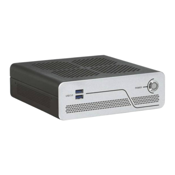
KBox B-201-RPL - Preliminary User Guide, Rev 0.5 4/ Product Features Before working with the KBox B-201-RPL, Kontron recommends that users take a few minutes to study this chapter and learn about the various parts and features. 4.1. Front Panel The front panel features the power button, two USB 3.2 Gen 1 ports, and ventilation openings for air-output. -
Page 23: Rear Panel
The USB 3.2 Gen 2/Gen 1 Type-A ports are backward compatible enabling the connection of both USB 3.0 or USB 2.0 compatible devices. Kontron recommends the use on USB 3.2 Gen 2/Gen 1 compliant devices or cables only. The use of devices and cables that violate the USB 3.2 Gen 2/Gen 1 specification may cause conditions such as non-... -
Page 24: Usb 2.0 Ports
KBox B-201-RPL - Preliminary User Guide, Rev 0.5 4.2.3. USB 2.0 Ports The two USB 2.0 ports enable the connection of USB 2.0 devices only. For the pin assignment, see Chapter 13.5: USB 2.0 Port Pin Assignment. 4.2.4. Display Port (DP) The four DP V1.4a ports are Dual mode/ Display Port ++ compatible with a maximum resolution of 7680 x 4320 @... -
Page 25: Audio (Line-In, Line-Out)
KBox B-201-RPL - Preliminary User Guide, Rev 0.5 4.2.6. Audio (Line-In, Line-Out) The two audio connectors audio Line-input (Line-in/MIC) and Headphone output (Line-out) enable the connection of full High Definition (HD) devices. Line-Input Supports: • Line: stereo max. 1.3 Vrms (Gain=0 dB) input voltage. -
Page 26: Dc In 24Vdc (Option)
KBox B-201-RPL - Preliminary User Guide, Rev 0.5 4.2.10. DC IN 24VDC (option) The optional 3-pin DC IN 24 VDC power connector connects to a user defined external 24 VDC power supply using the supplied mating power connector and wiring supplied by the user. -
Page 27: Left And Right Side
KBox B-201-RPL - Preliminary User Guide, Rev 0.5 4.3. Left and Right Side Figure 5: Left Side and Right Side Ventilation openings (air-output) 2x threaded screw holes for wall mount brackets www.kontron.com // 27... -
Page 28: Top Cover And Bottom Side
KBox B-201-RPL - Preliminary User Guide, Rev 0.5 4.4. Top Cover and Bottom Side The top cover features ventilation openings, a metal mesh and a metal plate with a circular opening. The circular opening’s position above the internal fan aids ventilation and the metal mesh prevents unwanted items from entering the product. -
Page 29: 5/ System Expansion
KBox B-201-RPL - Preliminary User Guide, Rev 0.5 5/ System Expansion 5.1. Before Expanding Before expanding the KBox B-201-RPL users must consider the product’s maximum allowed power consumption and take cooling into consideration. 5.2. Drive Bay The external drive bay supports one removable 2.5” SSD drive or 2.5” SSD dual M.2 RAID (RAID 0/1) module. -
Page 30: Reference Expansion Devices
KBox B-201-RPL - Preliminary User Guide, Rev 0.5 5.4. Reference Expansion Devices For a list of the KBox B-201-RPL reference expansion devices, visit Kontron’s Customer Section. www.kontron.com // 30... -
Page 31: 6/ Thermal Management
6/ Thermal Management 6.1. Active Cooling The KBox B-201-RPL is actively fan cooled. An internal processor fan draws in air through the top cover’s ventilation openings and distributes the incoming air over critical internal components before the air exits through the ventilation openings on the right, left, front and rear sides. -
Page 32: Mount Orientation
KBox B-201-RPL - Preliminary User Guide, Rev 0.5 6.2. Mount orientation The permitted mounting orientations are horizontal with the top side facing upward and vertical in all mount orientations. Mounting the product with the top cover facing downwards is not permitted. If the top cover faces downwards, not enough air enters the product to cool the processor adequately. -
Page 33: 7/ Assembly
7/ Assembly 7.1. Before Assembling Before opening the KBox B-201-RPL to access internal components, observe the safety instructions within this chapter and the safety instructions in Chapter 2/General Safety Instructions. For third party products, consult the documentation provided by the components manufacturer. Kontron recommends expanding the product, before installation. -
Page 34: Installing And Removing An M.2 Module
KBox B-201-RPL - Preliminary User Guide, Rev 0.5 Lift the top cover a few centimeters at the rear of the chassis and pull the top cover gently away from the front panel to release the top cover from the front-panel-holding-brackets. -
Page 35: Opening The Drive Bay
KBox B-201-RPL - Preliminary User Guide, Rev 0.5 Secure the M.2 module by pressing down on the free end, and carefully secure with a screw to the corresponding nut on the motherboard, until flat with the motherboard. Do not use force when fastening the mounting screw. Too much force may damage the motherboard nut. -
Page 36: Installing And Removing 2.5" Ssd Drive
KBox B-201-RPL - Preliminary User Guide, Rev 0.5 To open the drive bay cover, perform the following: Close all applications. Shut down the product properly using the power button and disconnect the power cable from the power source. Disconnect all peripherals. -
Page 37: Installing And Removing 2.5" Ssd Dual M.2 Raid Module
KBox B-201-RPL - Preliminary User Guide, Rev 0.5 Position the SSD in the drive bay with the SSD’s connector facing the SATA connector in the drive bay. Align the SSD’s connector with the internal SATA connector. Press down and gently push the SSD into the SATA connector. -
Page 38: Figure 13: Drive Bay With 2.5" Ssd Dual M.2 Raid Module
KBox B-201-RPL - Preliminary User Guide, Rev 0.5 Figure 13: Drive Bay with 2.5” SSD dual M.2 RAID Module 2.5” SSD dual M.2 RAID module with two M.2 SSD modules (installed on the bottom side) SATA connector To install a 2.5” SSD dual M.2 RAID module, perform the following: Close all applications. -
Page 39: Connecting The Wi-Fi Antenna (Option)
SSD’s screw hole with the 2.5” SSD dual RAID module’s nut. Secure with the screw retained in step 6. Kontron recommends replacing a faulty drive with a drive of the same capacity and type as the mirrored drive. When different capacity drives are used, the working capacity is only as large as the smallest drive’s capacity. -
Page 40: 8/ Installation
8/ Installation 8.1. Before Installing Before installing the KBox B-201-RPL in the operating environment, ensure that the operating environment meets the specification stated within this user guide, and that there is sufficient access to the product’s power connector, and the front and rear panel I/O connectors. -
Page 41: Chassis Feet
KBox B-201-RPL - Preliminary User Guide, Rev 0.5 Support the power and I/O cables to minimize the strain on the product’s connectors. Ensure there is enough clearance for users to • Connect cables on the rear I/O panel • Access the power-on button on the front panel •... -
Page 42: Mounting Brackets (Option)
KBox B-201-RPL - Preliminary User Guide, Rev 0.5 To mount on the vertical stand, perform the following: Lie the product with either the left or right side facing upwards. Position the vertical stand on the side of the chassis. Aline the two vertical stand screw holes with the two threaded screw holes on the side of the chassis. -
Page 43: Figure 19: Keep Out Areas - With Top Cover Facing The Mount Surface
KBox B-201-RPL - Preliminary User Guide, Rev 0.5 Obstructing the ventilation openings may cause overheating. To avoid overheating: • Do not to place items directly in front of the top cover ventilation openings • Observed that all ventilation openings are not covered or obstructed by objects... -
Page 44: Mounting Brackets Desktop
KBox B-201-RPL - Preliminary User Guide, Rev 0.5 Figure 20: Keep Out Areas – with Bottom Side facing the Mount Surface 10 mm 10 mm 10 mm 10 mm 10 mm 10 mm 10 mm 10 mm Installing the dual Wi-Fi antennas on the rear panel increases the keep out clearance to 45 mm and 130 mm from Wi-Fi hinge. -
Page 45: Mounting Brackets Wall
KBox B-201-RPL - Preliminary User Guide, Rev 0.5 Both mounting brackets must be used to mount the product to the mount surface. Install the mounting brackets on the product before mounting on the mount surface. 8.4.2. Mounting Brackets Wall To mount the product on a wall use the Wall Mount Set, see Table 2: Accessories. With the top cover facing outwards, use the mounting bracket holes (Figure 18, pos. -
Page 46: Vesa 100 Mount Assembly (Option)
KBox B-201-RPL - Preliminary User Guide, Rev 0.5 8.5. VESA 100 Mount Assembly (option) The VESA mount assembly mounts the product and the external power supply on the rear side of a VESA 100 monitor. Figure 23: VESA Mounting Assembly Kit... -
Page 47: Figure 25: Inserting The Velcro® Band
Secure the power supply by opening the self-gripping sides and pulling the band away from the D-ring as far as possible and re-securing the band tightly. Figure 27: VESA Mount Assembly with KBox B-201-RPL and Power Supply www.kontron.com // 47... -
Page 48: Vesa 100 Mount
KBox B-201-RPL - Preliminary User Guide, Rev 0.5 8.5.1. VESA 100 Mount The VESA 100 mount assembly mounts either directly on the rear side of the monitor, see Chapter 8.5.1.1: Mounting on non VESA Mount Stand Monitor or on the rear side of the monitor using the monitors stand, see Chapter 8.5.1.2: Mounting on Monitor with VESA 100 Stand. -
Page 49: Figure 30: Vesa Monitor Stand Assembly
KBox B-201-RPL - Preliminary User Guide, Rev 0.5 8.5.1.2. Mounting on Monitor with VESA 100 Stand Remove the monitor’s stand. Feed the supplied four supplied (M4x 20 mm) screws through the four mounting holes on the monitor’s stand and attach one of the supplied spacers to the screw’s free end (Figure 30) -
Page 50: 9/ Starting Up
9/ Starting Up 9.1. Before Starting Before connecting the KBox B-201-RPL to power, read the instructions in this user guide and observe the safety instructions in Chapter 2/ General Safety Instructions. The product comes hardware configured, and on request with a pre-installed Operating System (OS) and all the necessary drivers (in accordance with the ordered hardware configuration). -
Page 51: Connecting The External Ac/Dc (150 W) Power Supply
Only connect the product to the supplied external power supply providing the voltage type (AC or DC) and the input power (max. current) specified on the Kontron Product Label and meeting the requirements of the Limited Power Source (LPS) and Power Source (PS2) of UL/IEC 62368-1. -
Page 52: Wiring The 3-Pin Mating Power Connector
KBox B-201-RPL - Preliminary User Guide, Rev 0.5 9.3.1. Wiring the 3-pin Mating Power Connector Figure 34: DC IN 3-pin Power Connector and 3-pin Mating Power Connector 3-pin DC IN power connector (PSC 1.5/ 3-M) Clamp for earth wire 3-pin mating power connector (PSC 1.5/ 3-F) -
Page 53: Switching On/Off
Pay attention to the manufacturer’s OS specifications for integrated hardware components For information regarding supported software, see Table 12: Software Specification. To download relevant drivers for hardware components, visit Kontron’s Customer Section Pay attention to the manufacturer OS specifications relating to integrated hardware components. -
Page 54: 10/ Bios
BIOS The KBox B-201-RPL uses the AMI Aptio 5.x (uEFI) BIOS supported by the motherboard. This chapter informs user how to start the BIOS, use the BIOS setup to configure, and perform a BIOS update. Note that BIOS features are open to change and may not be available in the latest version of the motherboard’s BIOS. -
Page 55: Bios Navigation
<RETURN> key executes a command or selects a submenu 10.4. BIOS Update To ensure compatibility with new OS, hardware, software or to integrate new BIOS functions Kontron recommends regular BIOS updates. Additionally, if a problem cannot be solved using a new driver, Kontron recommends updating the BIOS. 10.4.1. -
Page 56: Recover Bios
To recover the BIOS, perform the following: Close all applications. Shut down the product properly and disconnect the power cable from the power source. Copy the BIOS ZIP package content (K3833-Q1.ROM file) in Kontron’s Customer Section to a FAT32 formatted USB stick. -
Page 57: 11/ Raid
KBox B-201-RPL - Preliminary User Guide, Rev 0.5 11/ RAID The KBox B-201-RPL supports a factor installed RAID array within the drive bay. 11.1. Drive Bay RAID Array The drive bay RAID array is factory installed and RAID 1 by default. -
Page 58: Drive Bay Raid Software
KBox B-201-RPL - Preliminary User Guide, Rev 0.5 Insert into the drive bay with the side of the 2.5” SSD dual M.2 RAID module with the two M.2 SSDs modules facing the inside of the drive bay. Switch on the product. Place a small non-conductive blunt-utensil underneath the 2.5”... -
Page 59: Table 8: S.m.a.r.t. Information Memory Attributes Examples
KBox B-201-RPL - Preliminary User Guide, Rev 0.5 Table 8: S.M.A.R.T. Information Memory Attributes Examples Memory-attributes Later bad Average erase Unexpected power loss Power on hours Device Life Temperature Power cycle Spare block Flash ID Total bad block Program fail... -
Page 60: 12/ Product Specification
KBox B-201-RPL - Preliminary User Guide, Rev 0.5 Product Specification 12.1. Block Diagrams Figure 37: Block Diagram KBox B-201-RPL KBox B-201-RPL 4x DisplayPort Dual Channel DDR5-4800 SODIMM (up to 64 GB) 1x LAN (1 GbE) 1x LAN (2.5 GbE) Fan Connector System Fan 13th Gen. -
Page 61: Hardware Specification
KBox B-201-RPL - Preliminary User Guide, Rev 0.5 12.2. Hardware Specification Table 11: Hardware Specification Product KBox B-201-RPL Motherboard Type K3833-Q mini-ITX Processors Intel® 13 Gen Core™ processors and Pentium® Gold processor Processors Cores Base Freq. Turbo Freq Base Power i9-13900E 1.8 GHz... -
Page 62: Power Specification
Power Rating 150 W Only connect the product to the external AC/DC power supply supplied by Kontron and providing the voltage type (AC or DC) and the input power (max. current) specified on the Kontron Product Label and meeting the requirements of the Limited Power Source (LPS) and Power Source (PS2) of UL/IEC 62368-1. -
Page 63: Power Protection
The minimum off state time, to allow internal voltages to discharge, depends on the power supply used and additional electrical factors. To determine the required off state time, each case must be considered individually. For more information, contact Kontron Support. 12.4.4. -
Page 64: Potential Equalization
VESA (D x W x H) 10.4 mm x 402.9 mm x 180 mm (0.41” x 15.86” x 7.09”) For the products 3D STEP data, visit Kontron’s Customer section and select the product KBoxB> KBox B-201-RPL> KBox B-201-RPL Documentation. www.kontron.com... -
Page 65: Dimension Diagrams
KBox B-201-RPL - Preliminary User Guide, Rev 0.5 12.6.1. Dimension Diagrams For detailed mechanical information, refer to the outline dimension diagrams in this chapter. Each dimension drawing shows the main external mechanical dimensions. Figure 38: Dimensions Front Panel Figure 39: Dimensions Rear Panel Figure 40: Dimensions Top Cover www.kontron.com... -
Page 66: Figure 41: Dimensions Bottom Side
Figure 42: Dimensions Right Side and Left Side 10 mm 10 mm 190 mm 190 mm 60 mm For the products 3D STEP data, visit Kontron’s Customer section and select the product KBoxB> KBox B-201-RPL> KBox B-201-RPL Documentation www.kontron.com // 66... -
Page 67: Dimension Diagrams- Wall Mount Brackets
Figure 43: Dimensions with Mounting Brackets Ø 4.5mm 230 mm 10.5 mm Ø 8.5 mm 160 mm 190 mm 250 mm For the products 3D STEP data, visit Kontron’s Customer section and select the product KBoxB> KBox B-201-RPL> KBox B-201-RPL Documentation www.kontron.com // 67... -
Page 68: Compliance
KBox B-201-RPL - Preliminary User Guide, Rev 0.5 12.7. Compliance The KBox B-201-RPL plans to comply with the relevant requirements and the approximation of the laws relating to the CE Mark for non-Wi-Fi variants and CE Radio Equipment Directive (RED) for Wi-Fi variants, and the standards that are constitutional parts of the declaration. -
Page 69: Table 20: International Compliance
KBox B-201-RPL - Preliminary User Guide, Rev 0.5 The KBox B-201-RPL plans to comply with the following country specific certifications. Table 20: International Compliance USA/CANADA FCC 47 CFR Part 15 (Class B) and ICES-003 Complies with part 15 FCC rules and regulations of title 47 of the CFR rules for class B products;... -
Page 70: 13/ Connectors And Leds
Only connect the product to an external 24 VDC power supply providing the input power (max. current) specified on the Kontron Product Label and meeting the requirements of the Limited Power Source (LPS) and Power Source (PS2) of UL/IEC 62368-1. -
Page 71: Usb 3.2 Gen 2/1 Port Pin Assignment
KBox B-201-RPL - Preliminary User Guide, Rev 0.5 The wiring is not part of the delivery and must be provided by the user. • Use copper wire only if the field wiring terminal is for copper wire connection only •... -
Page 72: Usb 2.0 Port Pin Assignment
KBox B-201-RPL - Preliminary User Guide, Rev 0.5 13.5. USB 2.0 Port Pin Assignment Table 25: USB 2.0 Connector Pin Assignment Signal Name 4-pin USB 2.0 (Type-A) Connector +5 V (fused protected) Data- Data+ 13.6. Display Port (DP) V1.4a Pin Assignment... -
Page 73: Com Port Pin Assignment
KBox B-201-RPL - Preliminary User Guide, Rev 0.5 13.8. COM Port Pin Assignment Table 28: RS232 Connector Pin Assignment RS232 RS232 D89 Connector 13.9. Audio Line-out and Line-in Connector Pin Assignment Table 29: Audio Line-out Audio Line-in Pin Assignment Jack... -
Page 74: Jumpers
Figure 44: Recover BIOS Jumper Default jumper setting Recover position (orange) Table 30: Recover BIOS Jumper Pins State 24-pin Front Panel Header 20-22 Default 22-24 Recover BIOS Default Recover BIOS For further motherboard information, visit Kontron’s K3833-Q mITX motherboard website. www.kontron.com // 74... -
Page 75: 14/ Maintenance
The CR2032 lithium battery is located in a vertical battery holder on the product’s motherboard. The CR2032 lithium battery must be replaced with an identical 3 Volt lithium battery or a Kontron recommended lithium battery. To replace the Lithium battery, perform the following: Close all applications. - Page 76 KBox B-201-RPL - Preliminary User Guide, Rev 0.5 Gently push the battery downwards until the metal clamp locks the battery. Close the product, see Chapter 7.2: Opening the Product, step 7. Never use metal tools such as tweezers to grab the lithium battery. This will shortcut both terminals, and can damage the lithium battery! Only use suitable (non-metal) tools.
-
Page 77: 15/ Storage And Transportation
The storage facility must meet the products environmental storage requirements as stated within this user guide. Kontron recommends keeping the original packaging material for future storage or warranty shipments. -
Page 78: 16/ Technical Support
RMA number. The buyer accepts responsibility for all freight charges for the return of goods to Kontron's designated facility. Kontron will pay the return freight charges back to the buyer's location in the event that the equipment is repaired or replaced within the stipulated warranty period. Follow these steps before returning any product to Kontron. -
Page 79: Warranty
Limitation/Exemption from Warranty Obligation In general, Kontron shall not be required to honor the warranty, even during the warranty period, and shall be exempted from the statutory accident liability obligations in the event of damage caused to the product due to failure to observe the following: ... -
Page 80: Table 31: List Of Acronyms
KBox B-201-RPL - Preliminary User Guide, Rev 0.5 List of Acronyms Table 31: List of Acronyms BIOS Basic Input Output System UEFI Unified Extensible Firmware Interface BlueTooth Universal Serial Bus Code of Federal Regulations Voltage Common Collector Communication port Voltage Direct Current... -
Page 81: About Kontron
KBox B-201-RPL – Preliminary User Guide, Rev 0.5 About Kontron Kontron is a global leader in IoT/Embedded Computing Technology (ECT). Kontron offers individual solutions in the areas of Internet of Things (IoT) and Industry 4.0 through a combined portfolio of hardware, software and services. With its standard and customized products based on highly reliable state-of-the-art technologies, Kontron provides secure and innovative applications for a wide variety of industries.
Need help?
Do you have a question about the KBox B-201-RPL and is the answer not in the manual?
Questions and answers