
Related Manuals for Jasic RAZORCUT 40PCI


Summary of Contents for Jasic RAZORCUT 40PCI
- Page 1 OPERATING RAZORCUT MANUAL 4OPCI 40 AMP PLASMA CUTTER WITH INTERNAL AIR COMPRESSOR SKU:RC40PCi...
-
Page 3: Table Of Contents
RAZORCUT CONTENTS SAFETY TECHNICAL DATA MACHINE LAYOUT WHAT’S IN THE BOX GENERAL OPERATING TIPS SETUP FOR INTERNAL AIR PLASMA CUTTING SETUP FOR EXTERNAL AIR PLASMA CUTTING PLASMA CUTTING TECHNOLOGY PLASMA CUTTING TIPS & TECHNIQUES TORCH BREAKDOWN & SPARES MACHINE PARTS BREAKDOWN FAQ &... - Page 4 ™ WARRANTY • 3 Years from date of purchase. • JASIC Technologies America Inc Ltd warranties all goods as specified by the manufacturer of those goods. • This Warranty does not cover freight or goods that have been interfered with.
-
Page 5: Safety
SAFETY Welding and cutting equipment can be dangerous to both the operator and people in or near the surrounding working area if the equipment is not correctly operated. Equipment must only be used under the strict and comprehensive observance of all relevant safety regulations. Read and understand this instruction manual carefully before the installation and operation of this equipment. - Page 6 SAFETY Fire hazard. Welding/cutting on closed containers, such as tanks, drums, or pipes, can cause them to explode. Flying sparks from the welding/cutting arc, hot workpiece, and hot equipment can cause fires and burns. Accidental contact of the electrode to metal objects can cause sparks, explosion, overheating, or fire. Check and be sure the area is safe before doing any welding/cutting.
- Page 7 SAFETY CAUTION 1. Working Environment. i. The environment in which this welding/cutting equipment is installed must be free of grinding dust, corrosive chemicals, flammable gas or materials etc., and at no more than a maximum of 80% humidity. ii. When using the machine outdoors, protect the machine from direct sunlight, rainwater and snow, etc.; the temperature of the working environment should be maintained within -10°C to +40°C.(14-104F) iii.
-
Page 8: Technical Data
TECHNICAL DATA RAZORCUT 4o PLASMA CUTTER WITH COMPRESSOR Key Features: • Built-in Air Compressor • External and Internal Compressor capability • Pilot Arc Start • 3/8" Clean Cut • 1/2" Severance • CNC Port • Perforated Cutting Option • Test Air button •... -
Page 9: Machine Layout
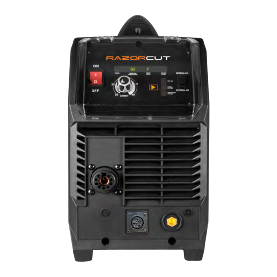
MACHINE LAYOUT RAZORCUT Front Panel Layout 1. On/Off Power Switch 2. Current Control Knob 3. Cut Mode Switch 4. Internal/External Air Switch 5. Power LED 6. Overload/Power Error LED 7. Torch Error LED 8. Cutting Power LED 9. Plasma Torch Connection 10. - Page 10 MACHINE LAYOUT Additional Machine Control Information 1. Power LED • Lights up when input power connected and the machine switched on. 2. Overload / Power Error LED • Lights up when over-voltage, over-current or electrical overheating (due to exceeding duty cycle) is detected and protection is activated.
-
Page 11: What's In The Box
WHAT’S IN THE BOX RAZORCUT Includes: • 1 x J45XC-6 Torch Complete RAZOR CUT 40 AIR Plasma Cutter 19.5Ft J45XC Plasma Torch Air Regulator 10ft 200 AMP Earth Clamp Operating Manual Plug (Fitted) 40AMP PLASMA CUTTER WITH INTERNAL AIR COMPRESSOR CNC Plug Operating Manual (14 Pin) -
Page 12: General Operating Tips
GENERAL OPERATING TIPS Additional Machine Control Information Compressed Air Requirements A reliable and consistent supply of clean, dry compressed air is essential for proper operation. Although the machine contains its own internal air supply filtration system it is recommended the compressed air supply should have external filtration in the line feeding the machine, both a standard water trap (sintered bronze filter) and also a coalescing filter (for oil in the air). -
Page 13: Setup For Internal Air Plasma Cutting
SETUP FOR INTERNAL AIR PLASMA CUTTING Connect the plasma torch to the plasma torch Connect the earth clamp to the positive (+) connection. Tighten the nut once connected to dinse connection, twist to lock in place ensure a secure connection. Connect the plug into the socket, then Select INTERNAL air supply. - Page 14 SETUP FOR INTERNAL AIR PLASMA CUTTING Select Test Air by pressing the Cut Mode Connect the earth clamp to the work piece. Mode button until the Test Air icon lights up, to check that air is feeding correctly. RAZORCUT Select desired cutting mode by pressing the Set the current to turning the Current Control Cut Mode Mode button until the desired Knob.
- Page 15 SETUP FOR INTERNAL AIR PLASMA CUTTING Place and hold the torch vertical at the edge of Pull the trigger to energise the arc. When the the plate. cutting arc has cut through the edge of the plate start moving evenly in the direction you wish to cut.
-
Page 16: Setup For External Air Plasma Cutting
SETUP FOR EXTERNAL AIR PLASMA CUTTING Connect the plasma torch to the plasma torch Connect the earth clamp to the positive (+) connection. Tighten the nut once connected to dinse connection, twist to lock in place ensure a secure connection. Connect the plug into a 230v Power socket, Select EXTERNAL air supply. - Page 17 SETUP FOR EXTERNAL AIR PLASMA CUTTING Connect air supply to the Air Filter. Select Test Air by pressing the Cut Mode Mode button until the Test Air icon lights up. RAZORCUT Lift the Air Pressure Regulator Knob, then turn Push the Air Pressure Regulator Knob the knob until you reach an ideal reading of downwards to lock the reading in place.
- Page 18 SETUP FOR EXTERNAL AIR PLASMA CUTTING Connect the earth clamp to the work piece. Select desired cutting mode by pressing the Cut Mode button until the desired cutting mode up. RAZORCUT Set the current to turning the Current Control Place and hold the torch vertical at the edge of Knob.
- Page 19 Failure to do this will result in torch head damage. NOTES FOR USING THE MACHINE FOR CNC CUTTING Your RAZORCUT 40PCi is fitted with a RAZORCUT CNC Port with 12 female pins. Your machine is supplied with a male 12 pin connector.
-
Page 20: Plasma Cutting Technology
PLASMA CUTTING TECHNOLOGY Plasma cutters work by passing an electric arc through a gas that is passing through a constricted opening. The electric arc elevates the temperature of the gas to the point that it enters a 4th state of matter. We all are familiar with the first three: i.e., Solid, liquid, and gas. -
Page 21: Plasma Cutting Tips & Techniques
PLASMA CUTTING TIPS & TECHNIQUES Amperage The standard rule of thumb is the thicker the material, the more amperage required. On thick material, set the machine to full output and vary your travel speed. On thinner material, you need to turn down the amperage and change to a lower-amperage tip to maintain a narrow kerf. - Page 22 PLASMA CUTTING TIPS & TECHNIQUES Electrode condition A fixed gap is established between the electrode and the inside of the cutting tip — electrons arc across the gap, ionizing and superheating the air creating the plasma stream. The electrode contains an insert at the end made of a highly conductive material called hafnium.
-
Page 23: Torch Breakdown & Spares
J45XC JASIC TECHNOLOGIES AMERICA INC 25503 74th Ave S, Kent, WA 98032 Ph: 253-859-6277 , Fax: 253-859-6286 sales@razorweld.com PLASMA Plasma Cutting Torch Technical Data Current : 45 Amps Duty Cycle: 60%@40Amps Air pressure: 65-75 psi (4.5 -5.0bar) Flow: 3.55cfm (100l/m) -
Page 24: Machine Parts Breakdown
MACHINE PARTS BREAKDOWN 39 38 MACHINE SPARES MACHINE SPARES 7.2530.004 Handle 3.P628.4026-E Digital display PCB 7.3010.0705 machine cabinet 3.0628.1038-C Control PCB 7.0680.921 rear plastic panel 3.0628.7003 Inductance output PCB 7.1220.0705 fixing plate for fan 5.1850.0705 main transformer 6.7200.006-A 3.0628.6002 FRD PCB 7.3070.0705 fixing sealing plate for rear panel 7.4230.031... -
Page 25: Faq & Troubleshooting
WARNING: There are extremely dangerous voltage and power levels present inside this unit. Do not attempt to diagnose or repair unit by removing external cover unless you are an authorized JASIC repair facility 1. Power lamp and temperature lamp on. - Page 26 NOTES...
- Page 27 NOTES...
- Page 28 NOTES...
- Page 29 JASIC TECHNOLOGIES AMERICA INC 25503 74th Ave S, Kent, WA 98032 Ph: (+1) 253-859-6277 Fax:(+1) 253-859-6286) www.razorweld.com sales@razorweld.com "A JASIC GROUP COMPANY"...
Need help?
Do you have a question about the RAZORCUT 40PCI and is the answer not in the manual?
Questions and answers