Advertisement
Advertisement
Table of Contents

Related Manuals for Jasic TIG180P


Summary of Contents for Jasic TIG180P
- Page 1 TIG INVERTER INSTRUCTION MANUAL...
-
Page 2: Table Of Contents
Installation and Operation Caution Maintenance Spare Parts List Troubleshooting EC DECLARATION OF CONFORMITY We hereby declare that the following machines: TIG180P Dual Voltage / TIG200P AC/DC correspond to the following edicts and standards: EMC Directives: 73/23/EEC and 89/336/EEC European Standard: EN/IEC60974... -
Page 3: Warning
TIG Inverter Instruction Manual Warning Welding and cutting is dangerous to the operator, people in or near the working area, and the surrounding environment. Therefore, the performance of welding and cutting must only be done under the strict and comprehensive observance of all relevant safety regulations. Please read and understand this instruction manual carefully before installation and operation. -
Page 4: General Description
General Description This welding machine is manufactured with advanced inverter technology. With power component MOSFET and PWM technology, the inverter converts DC voltage, which is rectified from input AC voltage, to high 100KHz frequency AC voltage; as a consequence, the voltage is transformed and rectified. -
Page 5: Main Parameters
TIG Inverter Instruction Manual Main Parameters TIG180P TIG200P Fuse Rating 16 amp 20 amp Generator + / − 15% + / − 15% Friendly Input Power 110 / 220 volt AC 230 volt Voltage (single phase) (single Phase) Rate Input 3.9 KVA... -
Page 6: Circuit Diagram
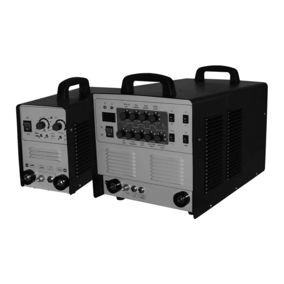
Input voltage is decided by the length of the cable, therefore longer than standard cables will reduce the amount of resistance. It is recommended to maintain the standard length of main cables and torch cables. TIG180P 1 : Mains Lead 2 : Arc / Torch Lead Connection (35/50 Dinze) - Page 7 TIG Inverter Instruction Manual 7 : Slope Out Timer Control 8 : MMA / TIG Mode Switch 9 : Mains On/Off Switch 10 : Current Output Control 11 : Slope In Control Timer 12 : O.C. Warning Light 13 : 2 Pole / 4 Pole Switch (Continuous weld / Non continuous weld) 3 4 5 TIG 200P AC/DC 1 : Mains Lead...
-
Page 8: Caution
1 : Gas Pre Flow Timer 2 : Output Current Control (Main) 3 : Base CUrrent Setting 4 : Slope Out Timer 5 : Arc Force Adjustment 6 : Pulse Frequency Control 7 : Pulse Duty Control 8 : Clean Area / Width Adjustment 9 : Post Flow Adjustment Caution 1. -
Page 9: Maintenance
TIG Inverter Instruction Manual supply current exceeds the stipulated value, it is possibly damaging to the components of this welding equipment. 2.4 An earth terminal is available for this welding equipment. Connect with the earth cable to avoid static and electric shock. 2.5 DO NOT contact the output terminal when the welding operation is performed. -
Page 10: Spare Parts List
Spare Parts List Part Number Description TIG180P TIG200P Front Panel Cover Carrying Strap / Handle Dial Dinze Socket On / Off Switch Power Cable Internal Fan Bottom PCB Heat Sink Center PCB Rubber Feet Top PCB TIG180p... - Page 11 TIG Inverter Instruction Manual TIG200p...
-
Page 12: Troubleshooting
Troubleshooting Please note: In the event of a fault with this inverter welding machine, only qualified electricians are authorised to undertake repairs. Fault Symptoms Reason 1. Possible failure of voltage input. Consult an authorised No output from machine, O.C. Light not lit, internal fan technician.
Need help?
Do you have a question about the TIG180P and is the answer not in the manual?
Questions and answers