
Related Manuals for Gooxi AS201-G3


Summary of Contents for Gooxi AS201-G3
- Page 1 AS201-G3 Rackmount Server User Manual Document version: 01 Release date: 2023/12/28 Shenzhen Gooxi Information Security Co., Ltd.
-
Page 2: Copyright Statement
Disclaimer Gooxi provides this user manual "as is" and to the extent permitted by law, makes no express or implied warranties or guarantees, including but not limited to merchantability, fitness for a particular purpose, non-infringement of any rights of others, and any warranties or guarantees regarding the use or inability to use this user manual. -
Page 3: Foreword
Foreword This manual is the product technical manual for the AS201 Whitley platform 2U model servers. It primarily provides an introduction and explanation of the product's appearance, structure, hardware installation, and basic configuration. Please note that this manual is intended for reference and research purposes for professional technical personnel. -
Page 4: Table Of Contents
Contents Statement ..............................1 Foreword ..............................2 1. Product Introduction ..........................5 1.1 Product Overview ........................5 1.2 Product Structure ......................... 6 1.3 Logical Structure ......................... 7 1.4 Product Specifications ......................... 8 2. Hardware Description .......................... 10 2.1 Front Panel ..........................10 2.1.1 Appearance ........................10 2.1.2 Indicator lights and buttons .................... - Page 5 3.2.3 Memory installation ....................29 3.2.4 M.2 installation ......................31 3.2.5 Server slide rail installation ..................31 4. Configuration Instructions ........................34 4.1.1 Power on and start ........................34 4.1.2 Initial data ..........................36 4.1.3 Configure BIOS ........................36 4.1.4 Configure BMC ........................37 5.
-
Page 6: Product Introduction
1.1 Product Overview The AS201 Whitely 2U Dual-Socket Rackmount Server is a versatile next-generation 2U dual-socket rackmount server introduced by Gooxi to meet the demands of the internet, IDC (Internet Data Center), cloud computing, enterprise markets, and telecommunications applications. It is suitable for IT core operations, cloud computing virtualization, high-performance computing, distributed storage, big data processing, enterprise or telecom applications, and other complex workloads. -
Page 7: Product Structure
Rear view 1- 2 1.2 Product Structure Physical structure of AS201 Whitely 2U dual-socket server varies according to different requirements. Taking the 8-bay model as an example, the description of various components of the server is as shown in the diagram below: Structure diagram 1-3 Name Name... -
Page 8: Logical Structure
Memory Module Rear Window Assembly CPU Heatsink Half-Height PCIe Expansion Channel Table 1-1 1.3 Logical Structure The AS201 Whitely 2U dual-socket rackmount server is shown in the figure below: Motherboard logic block diagram 1-4 The CPU employs the third generation Intel® Xeon® Scalable processors, utilizing the LGA4189 socket, with a TDP power consumption of 270W. -
Page 9: Product Specifications
chip, serving the purpose of IPMI remote management. It includes a VGA output port, a dedicated Gigabit RJ45 management network port, and is also connected to the PCH via RMII/NCSI. 1.4 Product Specifications Product Series AS201-D08R-G3 AS201-D12RE-G3 AS201-D25RE-G3 2U 8-bay 2U 12-bay 2U 25-bay Form Factor... - Page 10 Comply with RoHS2.0 RoHS Working Temperature 5℃~35℃/humidity 20%~80% RH non-condensing Temperature & Humidity Short-term storage (≤72 H): temperature -40℃~70℃/humidity 20%~90% RH Storage non-condensing (including packaging) Temperature & Long-term storage (>72 H): temperature 20°C~28°C/humidity 30%~70% RH non-condensing (including packaging) Humidity Table 1-2...
-
Page 11: Hardware Description
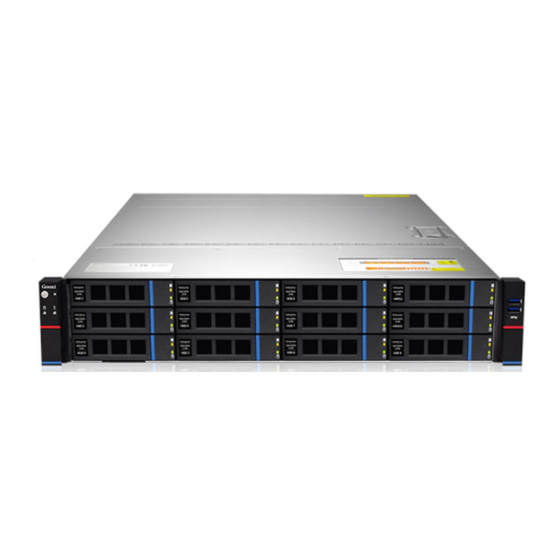
2. Hardware Description 2.1 Front Panel 2.1.1 Appearance 8 x 3.5" hard drive configuration Figure Name Name 3.5 inch hard drive USB 3.0 port _ Table 12 x 3.5" hard drive configuration Figure Name Name 3.5 inch hard drive USB 3.0 port _ Table 25 x 2.5"... -
Page 12: Indicator Lights And Buttons
2.1.2 Indicator lights and buttons Figure Indicator/button Indicator/button Power switch System alarm indicator button/indicator Reset server button Network port 1 connection status indicator Hard drive indicator Network port 2 connection status indicator LED status description Logo Indicator/button Status description Description of the power indicator light: Green (steady on): Indicates that the device has been powered on normally. -
Page 13: Interface
Note: Corresponds to the two 1GE Ethernet ports on the motherboard. Indicator lights for Ethernet ports corresponding to the network card slots. Network port Green (steady): Indicates a normal network connection. connection status Off: Indicates an unused or faulty network port. indicator light Note: Corresponds to the two 1GE Ethernet ports on the motherboard. - Page 14 Figure 2-6 2U supports 1 double-width high-performance GPU card + 4 half-height single-width high-performance GPU cards Figure 2U supports 1 double-width high-performance GPU card + 9 half-height single-width high-performance GPU cards Figure 2U supports 10 half-height full-length high-performance GPU cards ...
-
Page 15: Indicator Lights And Buttons
RJ45 Gigabit network port Riser module Table 2-7 (Refer to Figure 2-6) Note: The rear window of this product can be customized according to the needs. The above picture is for reference only, and the actual configuration shall prevail. Rear panel interface description ... -
Page 16: Processors
Supports 1 or 2 Intel third-generation Xeon scalable CPU. When configuring 1 processor, it needs to be installed in CPU 0 position. Processors configured on the same server must have the same model. For specific available system options, please consult Gooxi sales. ... -
Page 17: Memory
The location of the processor is shown in the figure below: Figure 2-11 2.4 Memory 2.4.1 Memory slot location This motherboard utilizes the Intel Whitely platform, paired with Intel Xeon ICE Lake CPUs. Each CPU supports 8 channels, and each channel supports 2 DIMMs. The motherboard can accommodate up to 16 DIMMs. -
Page 18: Memory Compatibility Information
Figure 2-12 2.4.2 Memory compatibility information The motherboard supports DDR4 RDIMM/LRDIMM server memory, and the memory frequency supports 2666/2933/3200. Note: The same server must use the same model of DDR4 memory, and all memory must run at the same speed. Likewise, the velocity value is the lowest of the following. The memory speed supported by the specific CPU. -
Page 19: Hard Drive Serial Number
8-bay tri-mode backplane, NVMe/SAS/SATA 8 x 3.5-inch Front Hard Drives Rear Hard Drive Module drives require Hard Drives (8 x 3.5/2.5) – (2 x 2.5) – Supports different cables; Pass-through Slots 0 to 7 support NVMe/SAS/SATA SAS drives require Configuration 2 SAS/SATA drives drives optional SAS... -
Page 20: Hard Drive Status Indicator
Supports hot swap. When configuring 2 power modules, it supports 1+1 redundant backup. For power modules configured on the same server, the power module models must be the same. For specific optional system options, please consult Gooxi sales. -
Page 21: Fans
The location of the power supply is shown in the figure below: Figure 2-17 The device is equipped with two identical pluggable power modules, both of which must be powered on simultaneously for the product to function correctly. Using a single power module alone is prohibited. 2.7 Fans ... -
Page 22: I/O Expansion
2.8 I/O expansion 2.8.1 PCIe slot location Figure 2-19 Figure 2-20 The slot position provided by the Riser3 module is slot0 and slot1. When using a two-slot PCIe expansion module, Slot0 is unavailable. The slot position provided by the Riser4 module is slot3 and slot4. When ... -
Page 23: Pcie Expansion Module
half height Slot 7 CPU1 PCIe 4.0 half length half height Slot 8 CPU0 PCIe 3.0 half length half height Slot 9 CPU0 PCIe 3.0 half length half height Slot 10 CPU0 PCIe 3.0 half length Note: ◆ The bus bandwidth is PCIe x16 slot backward compatible with PCIe x8 , PCIe x4, PCIe x1 PCIe card. -
Page 24: Pcba
2.5-inch hard drive module Figure 2-23 2.9 PCBA 2.9.1 Motherboard 2-24 Motherboard Figure... - Page 25 Name J45~J52 Connectors for system fans 1, 5, 2, 6, 3, 7, 4, 8 in order VR upgrade programming I2C connector J56, J57 2X 8Pins ATX CPU power connector 2x 12Pins ATX system power connector Power PMBus Connector Onboard USB 3.0 connector Front USB 3.0 Header x2 Front VGA connector SATA1 SATA2...
-
Page 26: Hard Drive Backplane
CONN1 2 RJ45 for USB3.0 and BMC TPM connector _ 2 RJ45 for the system VGA and system serial port UID button Reserved IPMB Device Power Connector Lane0~7 of PCIE SLOT1(x8)CPU1 PORT3 PCIe SLOT2(x16) CPU1 PORT2 PCIe Slot3 (X8) LANE8 ~ 15 of CPU1 PORT3 PCIe Slot4 (X8 OR X16) Labe8 ~ 15 of CPU1 Port1 PCIe Slot5 (X8 or None) Lane0 ~ 7 of CPU1 Port1 PCIE SLOT6(x16)CPU0 PORT2... - Page 27 Description Function Backplane power transmission 1、2 ATX power input connector, used for 12V power transmission Temperature-controlled 3、4、5、6 Used for 4pin fan interface socket 7、8 SFF-8643 12Gb SAS interface Backplane disk signal interface Table 2-16 12×3.5-inch expansion backplane TOP surface Figure 2-27 Description Function...
- Page 28 2×2.5 rear hard drive backplane-1 TOP surface Figure 2-29 Description Function SAS/SATA Hard Drive 1.Up to 12G/b SAS hard drive Connector 2.Up to 6G/b SATA hard drive Table 2-19 Bottom surface Figure 2-30 Description Function 1, 2 7PIN SATA interface SATA disk signal cable interface Backplane power transmission connector, 5 pin interface...
-
Page 29: Installation Instructions
3. Installation Instructions 3.1 Chassis Top Cover Installation Step 1: Lift the card slot at the opening position, push up in the direction indicated by the diagram. Figure 3-1 3.2 Installation of Accessories 3.2.1 CPU installation Step 1: Install the retention clip. Tilt the CPU at an angle as shown in the illustration, aligning the A1 corner (triangle mark) with one end of the retention clip. -
Page 30: Heatsink Installation
Figure 3-3 3.2.2 Heatsink installation Step 1: Remove the processor baffle (as shown in the figure below). Figure 3-4 Step 2: Align the heatsink with the mounting screws on the CPU socket bracket, and then tighten the heatsink's fixing screws in the indicated sequence (As shown below). - Page 31 The 8 memory slots controlled by CPU1 on the motherboard are as follows: DIMM A1, A2, DIMM B1, DIMM C1, and DIMM D1, D2, DIMM E1, DIMM F1. It's important to ensure that the notch on the memory module matches the notch on the DIMM slot.
-
Page 32: Installation
Table 3-1 In addition, it is necessary to specify: In the same channel, the memory module with the larger capacity must be inserted into the first slot. 3.2.4 M.2 installation Step 1: Install locating screw A according to the length of the M.2 card to be ... - Page 33 Figure 3-9 Step 2: Fasten the inner rails to the sides of the chassis. Figure 3-10 Step 3: Install the outer rails on the cabinet brackets and secure the screws. Figure 3-11 Note: When installing the guide rail, align it with the U-mark, and push it into place until you hear a click sound.
- Page 34 Figure 3-12 Note: When you push the chassis forward, you will hear a snapping sound. If you can’t push it, you need to pull down the buckle of the inner rail to continue to push the chassis gently. Step 5: Push the chassis forward until it cannot slide and make sure that the ...
-
Page 35: Configuration Instructions
4. Configuration Instructions 4.1.1 Power on and start Before powering on, it is necessary to ensure that all configurations of the server are installed in accordance with the corresponding specifications and standards, and keep the server turned off but not unplugged from the power supply. - Page 36 Figure 4-1 PCH state after G3 PCH state setting after G3, the menu options are: S0: Power on and start up directly S5: You need to press the Power button to turn on the power leave power state unchanged: Leave the power state unchanged . Default: S0 Log in to the iBMC management interface to perform remote power-on and ...
-
Page 37: Initial Data
Figure 4-2 For detailed usage of BMC and BIOS, please refer to the corresponding user manual. 4.1.2 Initial data BMC default account: admin BMC default password: admin BMC default address: 192.168.100.1 BIOS Default Password: N/A 4.1.3 Configure BIOS Press the <DEL>... -
Page 38: Configure Bmc
Figure 4-3 The Main interface contains the basic information of the BIOS system, such as the BIOS version number, CPU model, memory capacity, and the system time can be set. For detailed instructions, please refer to the "BIOS User Manual". Navigation key description: ... - Page 39 when starting the server. In the lower left corner of the logo screen, the IP address is displayed. After the server powers on, pay attention to the POST process. Press the <DEL> or <ESC> key on the keyboard to enter the BIOS Setup interface. Switch to the following screen: Figure 4-4 Configure IPV4 support :...
- Page 40 during every startup process. When the "Configuration Address Source" option is set to "Unspecified," it will display the network parameters (IPv4) for the system's shared Ethernet port. The displayed information includes the current IP configuration method, BMC IP, subnet mask, MAC address, router IP, and router MAC. BMC Dedicated Management Channel ...
- Page 41 will display the network parameters (IPv6) for the system's shared Ethernet port. BMC Dedicated Management Channel IPV6 Support Choose whether to support IPV6, the menu options are: Enabeld: support IPV6 Disabled: does not support IPV6 Default: Enabeld When changing from "Unspecified"...
- Page 42 Figure 4-6 This page sets the IP address of the BMC management network port.
-
Page 43: Appendix
If the above steps do not resolve the issue, try replacing the monitor with a known working one to confirm if the original monitor is faulty. If the issue persists, please contact Gooxi's customer service department for resolution. Front Panel Indicator Lights Alarm Refer to the instructions in the manual to determine the specific alarm information indicated by the front panel lights and buttons. - Page 44 Set static or dynamic IP and ensure ping connectivity. If the web interface does not open, try using a newer version of Internet Explorer. If the problem is not resolved, please contact Gooxi’s customer service department for further assistance and resolution.
-
Page 45: Scrap Recycling
6. Scrap Recycling For environmental protection and resource reuse, we earnestly ask you to properly handle discarded server products. Before discarding the server, we recommend that you completely demagnetize the storage media, clear data, and physically destroy them to ensure that your personal data is not leaked.
Need help?
Do you have a question about the AS201-G3 and is the answer not in the manual?
Questions and answers