
Related Manuals for Gooxi AS4110G-G4


Summary of Contents for Gooxi AS4110G-G4
- Page 1 AS4110G-G4 GPU Server User Manual 服务器用户手册 Document version: V1.0 Release date: 2024/02/22 Shenzhen Gooxi Information Security Co., Ltd.
-
Page 2: Statement
Gooxi provides this user manual "as is" and to the extent permitted by law, makes no express or implied warranties or guarantees, including but not limited to merchantability, fitness for a particular purpose, non-infringement of any rights of others, and any warranties or guarantees regarding the use or inability to use this user manual. -
Page 3: Foreword
Foreword This manual is the product technical manual for the AS4110G-G4 GPU server, mainly introducing and explaining the appearance, structure, hardware installation, and basic configuration of this product. This manual is intended for reference by professional technical personnel. Installation and maintenance of this product should only be carried out by experienced technical personnel. -
Page 4: Table Of Contents
Contents Statement..............................1 Foreword..............................2 1. Product Introduction ..........................5 1.1 Product Overview ........................5 1.2 Product Structure .........................5 1.3 Logical Structure .........................6 1.4 Product Specifications .........................7 2. Hardware Description ..........................8 2.1 Front Panel ..........................8 2.1.1 Appearance ........................8 2.1.2 Indicator lights and buttons ..................8 2.1.3 Interface ........................ - Page 5 2.8 I/O Expansion ..........................17 2.8.1 PCIe slot location ......................17 2.8.2 PCIe slot description ....................17 2.9 PCBA ............................18 2.9.1 Motherboard ........................ 18 2.9.2 Hard drive backplane ....................19 3. Installation Instructions ........................22 3.1 Chassis Top Cover Installation ..................... 22 3.2 Installation of Accessories .....................22 3.2.1 CPU installation ......................
-
Page 6: Product Introduction
1. Product Introduction 1.1 Product Overview AS4110G-G4 is a dual-socket GPU server that supports 10 dual-width GPU cards. It features 4 front bays for 3.5-inch drives, with optional support for 10 2.5-inch drives, and 4 rear bays for 2.5-inch drives. This server showcases exceptional capabilities in computational performance, storage expansion, and stability, making it ideal for emerging fields like artificial intelligence. -
Page 7: Logical Structure
Upper 3.5-inch Hard Drive Motherboard Module Rear Upper Cover Air Duct Switch Board Rear 2*2.5-inch Module Fan Module PCIe Expansion Slots Fan Bracket Power Supply Module 2*2.5-inch Hard Drive Memory Slots Rear Fan Module Table 1-1 1.3 Logical Structure The motherboard logic is shown in the figure below: Motherboard logic block diagram 1-2 CPU supports 1/2 Intel®... -
Page 8: Product Specifications
The BMC chip uses ASPEED's AST2600 control chip, supports IPMI remote management, VGA output port, and dedicated Gigabit RJ45 management network port. 1.4 Product Specifications Product Series AS4110G-G4 Form Factor 4U 4-bay Dimension 850mm*433mm*176.5mm(L*W*H) Processor Supports 1 or 2 Intel® Xeon® Scalable series processors... -
Page 9: Hardware Description
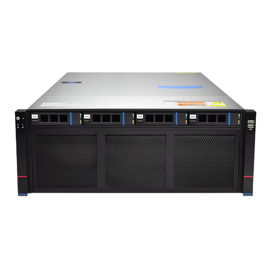
2.1.1 Appearance 4 x 3.5-inch hard drives Figure 2-1 Name Name left ear assembly right ear assembly 3.5-inch hard drive table 2-1 2.1.2 Indicator lights and buttons Figure 2-2 Indicator light/button Indicator light/button GOOXI Logo Hard Drive Activity Indicator Light... - Page 10 Status Indicator Light LED status description logo Indicator status description light/button GOOXI logo Description of the power indicator light: Green (steady on): Indicates that the device has been powered on normally. Green (blinking): Indicates that the device is in standby.
-
Page 11: Interface
Corresponds to the Ethernet port indicator of the network card. Network Port 2 Green (steady on): Indicates that the network port Connection is connected normally. Status Indicator Off: Indicates that the network port is not in use or Light faulty. Note: Corresponds to two 1GE network ports on the motherboard. -
Page 12: Indicator Lights And Buttons
Figure 2-4 Name Name power module PCIE expansion slot 2*2.5 inch hard drive 2.5 inch hard drive module module I/O panel 8038 fan module Table 2-5 2.2.2 Indicator lights and buttons Rear Panel Indicators Figure 2-5 Name Name Power module indicator Management network port... -
Page 13: Interface
Green (steady on): Indicates that the input and output are normal. Orange (steady on): Indicates that the AC power cord is unplugged or the power module is missing, and only one parallel-connected power module has AC input; the power module failure causes the output to be turned off, such as OVP, OCP, fan failure, etc. -
Page 14: Processor
Processors installed in the same server must be of the same model. For specific optional system components available for purchase, please consult Gooxi sales. Figure 2-7 2.4 Memory 2.4.1 Memory slot location This motherboard utilizes the Eagle Stream platform, paired with Intel® Xeon® Sapphire... -
Page 15: Memory Compatibility Information
The motherboard can support 16 DIMMs in total, with support for DDR5 RDIMMs memory. Memory frequencies supported include 4400/4800/5600MHz. The configuration is as shown in the following diagram: memory slot location Figure 2-8 2.4.2 Memory Compatibility Information The motherboard supports DDR5 RDIMM memory, with memory frequencies supported at 4400/4800/5600. -
Page 16: Storage
Figure 2-9 2.5 Storage 2.5.1 Hard drive configuration Maximum number Configuration Description hard drives (pieces) Front – Slots 0~3 SAS hard drive needs to be supported 4x3.5 inch hard support SAS/SATA by optional SAS pass-through card or drive hard drives RIAD card Rear Slots... -
Page 17: Hard Drive Status Indicator
Power module models installed in the same server must be identical. For specific optional system components available for purchase, please consult Gooxi sales. Figure 2-12 The device is equipped with 4 identical hot-swappable power modules, all of which need to be powered simultaneously for the product to function... -
Page 18: Fans
2.7 Fans Supports 11 fan modules. Supports hot-swappable. Supports variable fan speed. The fan module models installed in the same server must be identical. 2.8 I/O Expansion 2.8.1 PCIe slot location Figure 2-13 2.8.2 PCIe slot description When CPU1 is not in place, its corresponding PCIe slot is unavailable. -
Page 19: Pcba
75W. The power consumption of the PCIe card depends on the model of the card. Table 2-12 2.9 PCBA 2.9.1 Motherboard Motherboard Figure 2-14 Name 1、8 System fan 4-pin connector UID button COM port BMC_LAN/USB3.0 Rear VGA Rear USB2.0 RJ45 Gigabit network port CPU1 PCIE5.0 Port0(lane8~15) X8 MCIO connector CPU1 PCIE5.0 Port0(lane0~7) X8 MCIO connector 12Pin hard drive backplane power connector... -
Page 20: Hard Drive Backplane
4Pin rear backplane power connector NIC power connector 8Pin power board connector Motherboard and power communication control connector Front USB 3.0 connector 8-pin power board connector Front VGA connector 12-pin hard drive backplane power connector Riser power connector System fan 6-pin connector System fan 4-pin connector CPU0 PCIE5.0 Port3(lane0~7) X8 MCIO connector CPU0 PCIE5.0 Port3(lane8~15) X8 MCIO connector... - Page 21 socket 12G/b 6G/b SATA signal SFF-8643 12Gb SAS interface transmission SAS/SATA hard drive connector Support 12Gb/s SAS hard drive; 6Gb/s SATA hard drive; Table 2-14 2×2.5 rear SAS/SATA hard drive backplane TOP surface Figure 2-16 Description Function Support 12Gb/s SAS hard drive; 6Gb/s SATA SAS/SATA 硬盘连接器...
- Page 22 Figure 2-18 Description Function SFF-8639 hard drive Supports PCIe x4 U.2 interface, used for connector connecting NVMe SSD Table 2-17 Bottom surface Figure 2-18 Description Function Provides PCIe x8 interface for connecting MCIO Connector CPU and NVMe SSD Used for CPLD programming and version JTAG Debugging Interface upgrades Used for connecting PSU 4-pin plug to power...
-
Page 23: Installation Instructions
3. Installation Instructions 3.1 Chassis Top Cover Installation Step 1: Lift the card slot at the opening position, and push it toward the rear of the chassis. Figure 3-1 3.2 Installation of Accessories 3.2.1 CPU installation Step 1: Install the retention bracket and tilt the CPU at the angle shown in the ... -
Page 24: Heatsink Installation
Figure 3-3 3.2.2 Heatsink installation Step 1: Remove the processor baffle (as shown in the figure below). Figure 3-4 Step 2: Align the heatsink with the mounting screws on the CPU socket bracket, and then tighten the heatsink's fixing screws in the indicated sequence (As shown below). -
Page 25: Gpu Installation
Figure 3-5 CAUTION: The pins on the motherboard are very delicate and prone to damage. To avoid damaging the motherboard, please do not touch the processor or the processor socket contacts. 3.2.3 GPU installation Step 1: Take out the screws on the left and right sides of the front hard drive ... -
Page 26: Memory Installation
Figure 3-7 Step 3: Take out the GPU bracket and install the GPU card. Figure 3-8 After installing the GPU, reverse the installation process of the front hard drive module according to the image provided earlier. 3.2.4 Memory installation The 8 memory slots controlled by CPU0 on the motherboard are as follows: DIMM_A1 、... -
Page 27: Installation
It's important to ensure that the notch on the memory module matches the notch on the DIMM slot. Insert each DIMM module vertically into place to prevent incorrect installation. Figure 3-9 Figure 3-10 Note: Use memory modules with identical CAS latency values on this motherboard. -
Page 28: Server Slide Rail Installation
Figure 3-11 3.2.6 Server slide rail installation Step 1: Prepare two slide rails and pull out the inner rail. Figure 3-12 Step 2: Fasten the inner rails to the sides of the chassis. Figure 3-13 Step 3: Install the outer rails on the cabinet brackets and secure the screws. ... - Page 29 Figure 3-14 Note: When installing the guide rail, align it with the U-mark, and push it into place until you hear a click sound. Secure it firmly using M5 screws. Step 4: Align the chassis with the inner rails installed with the outer rails for ...
- Page 30 Note: During equipment maintenance, it is necessary to loosen the panel screws and pull the chassis lightly. Do not push or pull the chassis at random speed to avoid damage to the equipment.
-
Page 31: Configuration Instructions
4. Configuration Instructions 4.1 Initial Configuration 4.1.1 Power on and start Before powering on, it is necessary to ensure that all configurations of the server are installed in accordance with the corresponding specifications and standards, and keep the server turned off but not unplugged from the power supply. - Page 32 Figure 4-1 State After G3 The menu options for setting the state after entering G3 status are: S0: Power on and start up directly S5: You need to press the Power button to turn on the power leave power state unchanged: Leave the power state unchanged . Default: S5 State Log in to the iBMC management interface to perform remote power-on and ...
-
Page 33: Initial Data
Figure 4-2 For detailed usage of BMC and BIOS, please refer to the corresponding user manual. 4.1.2 Initial data BMC default account: admin BMC default password: Gooxi@123. BMC default address: 192.168.100.1 BIOS Default Password: N/A Be mindful of password security and remember to update your login credentials! 4.1.3 Configure BIOS... -
Page 34: Configure Bmc
Figure 4-3 The Main interface contains the basic information of the BIOS system, such as the BIOS version number, CPU model, memory capacity, and the system time can be set. For detailed instructions, please refer to the "BIOS User Manual". Navigation key description: ... - Page 35 After the server is powered on, turn it on. Pay attention to the POST process when starting the server. In the lower left corner of the logo screen, the IP address is displayed. After the server powers on, pay attention to the POST process. Press the ...
- Page 36 BMC IP, subnet mask, MAC address, router IP, and router MAC. BMC Dedicated Management Channel Configuration Address source Configure the BMC IP address allocation mode, the menu options are: Unspecified: No change to BMC parameters Static: BIOS static IP setting DynamicBmcDhcp: BMC runs DHCP to dynamically assign IP DynamicBmcNonDhcp: BMC runs the Non-DHCP protocol to dynamically assign IP...
- Page 37 IPV6 Support Choose whether to support IPV6, the menu options are: Enabeld: support IPV6 Disabled: does not support IPV6 Default: Enabeld When changing from "Unspecified" to other parameters, saving and rebooting will result in the options reverting to the "Unspecified" value. There is no need to configure the BMC IP during every startup process.
- Page 38 Figure 4-6 This page sets the IP address of the BMC management network port.
-
Page 39: Appendix
If the above steps do not resolve the issue, try replacing the monitor with a known working one to confirm if the original monitor is faulty. If the issue persists, please contact Gooxi's customer service department for resolution. Front Panel Indicator Lights Alarm Refer to the instructions in the manual to determine the specific alarm information indicated by the front panel lights and buttons. - Page 40 Set static or dynamic IP and ensure ping connectivity. If the web interface does not open, try using a newer version of Internet Explorer. If the problem is not resolved, please contact Gooxi’s customer service department for further assistance and resolution.
-
Page 41: Scrap Recycling
6. Scrap Recycling For environmental protection and resource reuse, we earnestly ask you to properly handle discarded server products. Before discarding the server, we recommend that you completely demagnetize the storage media, clear data, and physically destroy them to ensure that your personal data is not leaked.
Need help?
Do you have a question about the AS4110G-G4 and is the answer not in the manual?
Questions and answers