
Subscribe to Our Youtube Channel
Related Manuals for Gooxi AS401-G3


Summary of Contents for Gooxi AS401-G3
- Page 1 AS401-G3 Rackmount Server User Manual Document version: 01 Release date: 2023/03/17 Shenzhen Gooxi Information security Co., Ltd.
-
Page 2: Copyright Statement
Disclaimer Gooxi provides this user manual "as is" and to the extent permitted by law, makes no express or implied warranties or guarantees, including but not limited to merchantability, fitness for a particular purpose, non-infringement of any rights of others, and any warranties or guarantees regarding the use or inability to use this user manual. -
Page 3: Modification Record
Foreword This manual is the product technical manual for the AS401 Whitley platform 4U model servers. It primarily provides an introduction and explanation of the product's appearance, structure, hardware installation, and basic configuration. Please note that this manual is intended for reference and research purposes for professional technical personnel. -
Page 4: Table Of Contents
Contents Statement ..............................1 Foreword ..............................2 1. Product Introduction ..........................5 1.1 Product Overview ........................5 1.2 Product Structure ......................... 6 1.3 Logical Structure ......................... 7 1.4 Product Specifications ......................... 8 2. Hardware Description ..........................9 2.1 Front Panel ...........................9 2.1.1 Appearance ........................9 2.1.2 Indicator lights and buttons .................... - Page 5 3.2.5 Server slide rail installation ..................27 4. Configuration Instructions ........................30 4.1.1 Power on and start ........................30 4.1.2 Initial data ..........................32 4.1.3 Configure BIOS ........................32 4.1.4 Configure BMC ........................33 5. Appendix .............................. 38...
-
Page 6: Product Introduction
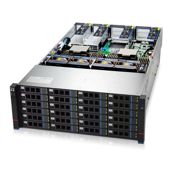
1.1 Product Overview The AS401 Whitely 4U Dual-Socket Rackmount Server is a versatile next-generation 4U dual- socket rackmount server introduced by Gooxi to meet the demands of the internet, IDC (Internet Data Center), cloud computing, enterprise markets, and telecommunications applications. It is... -
Page 7: Product Structure
Rear view 1- 2 1.2 Product Structure Physical structure of AS401 Whitely 4U dual-socket server varies according to different requirements. Taking the 24-bay model as an example, the description of various components of the server is as shown in the diagram below: Structure diagram 1-3 Name Name... -
Page 8: Logical Structure
1.3 Logical Structure The AS401 Whitely 4U dual-socket rackmount server is shown in the figure below: Motherboard logic block diagram 1-4 The CPU employs the third generation Intel® Xeon® Scalable processors, utilizing the LGA4189 socket, with a TDP power consumption of 270W. A single CPU supports 8 DDR4 channels, while 2 CPUs in total support 16 DDR4 slots. -
Page 9: Product Specifications
1.4 Product Specifications Product Series AS401-D24RE-G3 AS401-D36RE-G3 Form Factor 4U 24-bay 4U 36-bay Dimension 798*444*176.5mm(D*W*H) Processor Supports one or two 3rd Generation Intel® Xeon® Scalable series processors Memory The system features 16 DDR4 memory slots, supporting DDR4 LRDIMM/RDIMM with speeds of 2666/2933/3200 MHz. The maximum capacity per memory module is 256GB. -
Page 10: Hardware Description
2. Hardware Description 2.1 Front Panel 2.1.1 Appearance 24 x 3.5" hard drive configuration Figure 2-3 Name Name 3 .5 inch hard drive USB 3.0 port _ Table 2-3 2.1.2 Indicator lights and buttons Figure 2-4 Indicator/button Indicator/button Power switch System alarm indicator button/indicator Reset server button... -
Page 11: Interface
Description of the power indicator light: Green (steady on): Indicates that the device has been powered on normally. Green (blinking): Indicates that the device is in standby. Green off: Indicates that the device is not powered on. Power indicator Power button description: Short press this button in the power-on state, and the OS will shut down normally. -
Page 12: Rear Panel
USB 3.0 For accessing USB devices interface Table 2-6 2.2 Rear Panel 2.2.1 Appearance Appearance interface on the rear panel 4U with 5 dual-width, full-height, full-length high-performance GPU cards Figure 2-6 4U with 10 half-height, single-width high-performance GPU cards ... -
Page 13: Indicator Lights And Buttons
Note: The rear window of this product can be customized according to the needs. The above picture is for reference only, and the actual configuration shall prevail. Rear panel interface description VGA interface DB 15 Used to connect a display terminal, such as a monitor or KVM. -
Page 14: Processors
When configuring 1 processor, it needs to be installed in CPU 0 position. Processors configured on the same server must have the same model. For specific available system options, please consult Gooxi sales. The location of the processor is shown in the figure below: ... -
Page 15: Memory
Figure 2-9 2.4 Memory 2.4.1 Memory slot location This motherboard utilizes the Intel Whitely platform, paired with Intel Xeon ICE Lake CPUs. Each CPU supports 8 channels, and each channel supports 2 DIMMs. The motherboard can accommodate up to 16 DIMMs. -
Page 16: Memory Compatibility Information
2.4.2 Memory compatibility information The motherboard supports DDR4 RDIMM/LRDIMM server memory, and the memory frequency supports 2666/2933/3200. Note: The same server must use the same model of DDR4 memory, and all memory must run at the same speed. Likewise, the velocity value is the lowest of the following. The memory speed supported by the specific CPU. -
Page 17: Hard Drive Status Indicator
Supports hot swap. When configuring 2 power modules, it supports 1+1 redundant backup. For power modules configured on the same server, the power module models must be the same. For specific optional system options, please consult Gooxi sales. -
Page 18: Fans
The location of the power supply is shown in the figure below: Figure 2-14 2.7 Fans Supports 8 fan modules Supports hot swap Supports single fan failure Supports variable fan speed For fan modules configured on the same server, the fan module models must be the same ... -
Page 19: Pcie Slot Description
Figure 2-16 Figure 2-17 The slots provided by Riser1 module are Slot0, 1, 2, 3, 4, 5, 6, 7, 8, 9, 10. When using a PCIE expansion module with 2 slots, Slot1, 3, 5, 7, 9 are not available. 2.8.2 PCIe slot description When CPU1 is not in place, its corresponding PCIe slot is unavailable . -
Page 20: Pcie Expansion Module
half height half CPU 0 Slot 9 PCIe 3.0 length half height half CPU 0 Slot 10 PCIe 3.0 length Note: ◆ The bus bandwidth is PCIe x16 slot backward compatible with PCIe x8 , PCIe x4, PCIe x1 PCIe card. Upward is incompatible, that is, the bandwidth of the PCIe slot cannot be smaller than the bandwidth of the inserted PCIe card. -
Page 21: Pcba
2.9 PCBA 2.9.1 Motherboard Motherboard Figure 2-19 Name J45~J52 Connectors for system fans 1, 5, 2, 6, 3, 7, 4, 8 in order VR upgrade programming I2C connector 2X 8Pins ATX CPU power connector J56, J57 2x 12Pins ATX system power connector Power PMBus Connector Onboard USB 3.0 connector Front USB 3.0 Header x2... - Page 22 J61, J58 4U 12V Power connector, GPU power connector for atx power supply RAID KEY connector SSATA Sgpio connector Rear window 2 hard drive small board power supply connector S-SATA port 0~3 connector J37, J38 ISATA PORT 0~7 connector RTC battery connector DIMMB1/A1/D1/C1 The 2,1,4,3 channel memory of CPU0 is connected to the machine DIMMG1/H1/E1/F1...
-
Page 23: Hard Drive Backplane
PCIe SLOT10(x16) CPU0 PORT0 Table 2-14 2.9.2 Hard drive backplane 24×3.5 inch expansion backplane TOP surface Figure 2-20 Description Function SAS/SATA HDD Connector 1. Up to 12G/b SAS hard drive 2. Up to 6G/b SATA hard drive 3. Supports SAS/SATA hard drive hot swap Table 2-13 Bottom surface... - Page 24 PM8043 SXP 24Sx12G 24- Expander chip controller port 12G SAS Expander CPLD For data logic processing for 12G/b SAS or 6G/b SATA SFF-8643 12Gb SAS interface signal transmission Table 2-14 2×2.5 rear hard drive backplane-1 TOP surface Figure 2-22 Description Function SAS/SATA HDD...
-
Page 25: Installation Instructions
3. Installation Instructions 3.1 Chassis Top Cover Installation Step 1: Lift the card slot at the opening position, push up in the direction indicated by the diagram. Figure 3-1 3.2 Installation of Accessories 3.2.1 CPU installation Step 1: Install the retention clip. Tilt the CPU at an angle as shown in the illustration, aligning the A1 corner (triangle mark) with one end of the retention clip. -
Page 26: Heatsink Installation
3.2.2 Heatsink installation Step 1: Remove the processor baffle (as shown in the figure below). Figure 3-4 Step 2: Align the heatsink with the mounting screws on the CPU socket bracket, and then tighten the heatsink's fixing screws in the indicated sequence (As shown below). - Page 27 Figure 3-6 Figure 3-7 Note: Use memory modules with identical CAS latency values on this motherboard. We recommend using memory modules of the same capacity, frequency, and from the same manufacturer. The method for inserting the memory is as follows: Table 3-1...
-
Page 28: Installation
In addition, it is necessary to specify: IIn the same channel, the memory module with the larger capacity must be inserted into the first slot. 3.2.4 M.2 installation Step 1: Install locating screw A according to the length of the M.2 card to be ... - Page 29 Step 2: Fasten the inner rails to the sides of the chassis. Figure 3-1 0 Step 3: Install the outer rails on the cabinet brackets and secure the screws. Figure 3-11 Note: When installing the guide rail, align it with the U-mark, and push it into place until you hear a click sound.
- Page 30 Step 5: Push the chassis forward until it cannot slide and make sure that the screws are securely installed to complete the installation. Figure 3-13 Note: During equipment maintenance, it is necessary to loosen the panel screws and pull the chassis lightly. Do not push or pull the chassis at random speed to avoid damage to the equipment.
-
Page 31: Configuration Instructions
4. Configuration Instructions 4.1.1 Power on and start Before powering on, it is necessary to ensure that all configurations of the server are installed in accordance with the corresponding specifications and standards, and keep the server turned off but not unplugged from the power supply. - Page 32 Figure 4-1 PCH state after G3 PCH state setting after G3, the menu options are: S0: Power on and start up directly S5: You need to press the Power button to turn on the power leave power state unchanged: Leave the power state unchanged . Default: S0 Log in to the iBMC management interface to perform remote power-on and ...
-
Page 33: Initial Data
Figure 4-2 For detailed usage of BMC and BIOS, please refer to the corresponding user manual. 4.1.2 Initial data BMC default account: admin BMC default password: admin BMC default address: 192.168.100.1 BIOS Default Password: N/A 4.1.3 Configure BIOS Press the <DEL>... -
Page 34: Configure Bmc
Figure 4-3 The Main interface contains the basic information of the BIOS system, such as the BIOS version number, CPU model, memory capacity, and the system time can be set. For detailed instructions, please refer to the "BIOS User Manual". Navigation key description: ... - Page 35 After the server is powered on, turn it on. Pay attention to the POST process when starting the server. In the lower left corner of the logo screen, the IP address is displayed. After the server powers on, pay attention to the POST process. Press the ...
- Page 36 When the "Configuration Address Source" option is set to "Unspecified," it will display the network parameters (IPv4) for the system's shared Ethernet port. The displayed information includes the current IP configuration method, BMC IP, subnet mask, MAC address, router IP, and router MAC. BMC Dedicated Management Channel ...
- Page 37 BMC Dedicated Management Channel IPV6 Support Choose whether to support IPV6, the menu options are: Enabeld: support IPV6 Disabled: does not support IPV6 Default: Enabeld When changing from "Unspecified" to other parameters, saving and rebooting will result in the options reverting to the "Unspecified" value. There is no need to configure the BMC IP during every startup process.
- Page 38 Figure 4-6 This page sets the IP address of the BMC management network port.
-
Page 39: Appendix
If the above steps do not resolve the issue, try replacing the monitor with a known working one to confirm if the original monitor is faulty. If the issue persists, please contact Gooxi's customer service department for resolution. Front Panel Indicator Lights Alarm Refer to the instructions in the manual to determine the specific alarm information indicated by the front panel lights and buttons. - Page 40 Set static or dynamic IP and ensure ping connectivity. If the web interface does not open, try using a newer version of Internet Explorer. If the problem is not resolved, please contact Gooxi’s customer service department for further assistance and resolution.
Need help?
Do you have a question about the AS401-G3 and is the answer not in the manual?
Questions and answers