
Related Manuals for Ruijie RG-S5750-DP Series


Summary of Contents for Ruijie RG-S5750-DP Series
- Page 1 RG-S5750-DP Series Switch Hardware Installation and Reference Guide Document version: V1.8 Date: 2023-12-06 Copyright © 2023 Ruijie Networks...
- Page 2 Due to product version upgrades or other reasons, the content of this document will be updated from time to time. Ruijie Networks reserves the right to modify the content of the document without any notice or prompt. This manual is for reference only. Ruijie Networks endeavors to ensure content accuracy and will not shoulder...
- Page 3 Preface Intended Audience This document is intended for: Network engineers Technical support and servicing engineers Network administrators Technical Support Ruijie Networks website: https://www.ruijienetworks.com/ Technical support website: https://ruijienetworks.com/support Case portal: https://caseportal.ruijienetworks.com Community: https://community.ruijienetworks.com ...
-
Page 4: Product Overview
RG-S5750-DP series switches are next-generation high-performance, high-security, and multi-service Layer 3 Ethernet switches developed by Ruijie Networks. They are mainly applied to the access layer to provide line- rate switching and complete QoS policies, prioritizing traffic of some applications over others to ensure important data transmission without latency. - Page 5 SFP modules and SFP BIDI modules (see Appendix B) Module SFP+ modules, SFP+ cables, and SFP+ BIDI modules (see Appendix C) The supported optical module types may update without prior notification. Please contact Ruijie Networks for any updates. Power Module Slot Supported power module: RG-PA600I-P-F AC input...
- Page 6 Hardware Installation and Reference Guide Product Overview SFP+ Port 10GBase-R and 1000Base-X supported Each DP-OUT connector provides 24-channel 56 V DC/1.61 A output through an adapter, DP-OUT Connector with a maximum output power of 90 W per channel. Supported Not supported Maximum Power 85 W Consumption...
-
Page 7: Product Appearance
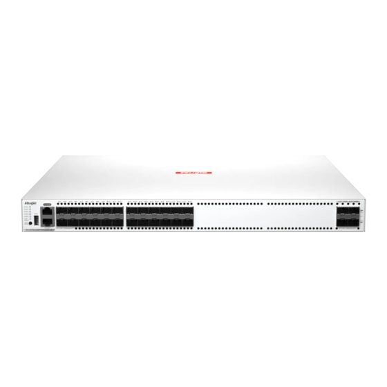
Hardware Installation and Reference Guide Product Overview Nameplate style: 1.2.1 Product Appearance The front panel of the RG-S5750-24SFP4XS24DP-UP provides 24 x 1000M SFP ports, 4 x 10GE SFP+ ports, 1 x MGMT port, 1 x console port, 1 x USB port, and 1 x DP-OUT connector, and the rear panel provides 3 x power module slots. - Page 8 Hardware Installation and Reference Guide Product Overview 1. Front Panel Figure 1-3 Front Panel of the RG-S5750-24SFP4XS24DP-UP Note: 1. Status LED 8. USB port 2. Management port status LED 9. Console port 3. PWR1 status LED 10. MGMT port 4. PWR2 status LED 11.
-
Page 9: Power Supply
Hardware Installation and Reference Guide Product Overview 2. Rear Panel Figure 1-4 Rear Panel of the RG-S5750-24SFP4XS24DP-UP Note: 1. Power module slot 1 (a filler 4. DP-OUT connector 2 (provides power supply for panel is required if the slot is external devices, 54 V) vacant) 5. -
Page 10: Heat Dissipation
Hardware Installation and Reference Guide Product Overview PSE total power consumption ≤ 800 W 1+2 redundancy PSE total power consumption ≤ 1600 W 2+1 redundancy PSE total power consumption > 1600 W No redundancy When two RG-PA600I-P-F power modules are used, check the redundancy status according to the following table. - Page 11 Hardware Installation and Reference Guide Product Overview Solid green The switch works properly. The temperature at air inlets and outlets exceeds the Solid yellow threshold. 1. The temperature at the air intake and exhaust vents well exceeds the threshold. Solid red 2.
- Page 12 Hardware Installation and Reference Guide Product Overview Blinking The port is sending or receiving data at the rate of 1/10 green Gbps.
- Page 13 Hardware Installation and Reference Guide Product Overview RG-PA600I-P-F Power Module The RG-PA600I-P-F is a swappable power module. The RG-PA600I-P-F is an AC module (AC/HVDC input and DC output) provides an output voltage of 56 V and an output power of up to 600 W. The switch can be powered on by one power module or multiple power modules.
- Page 14 Hardware Installation and Reference Guide Product Overview Operating 5% to 95% humidity Storage humidity 5% to 95% Operating altitude 0 m to 5,000 m (0 ft. to 16404.2 ft.) Table 1-4 Features of the RG-PA600I-P-F Power Module Feature Description Conformal Moisture-proof, salt spray-proof, mold-proof, insulation-proof, and leak-proof coating Undervoltage protection, output overcurrent protection, output overvoltage...
- Page 15 Hardware Installation and Reference Guide Product Overview The switch can be powered on by one power module or multiple power modules. If multiple power modules are used, the switch works in current-sharing mode. It supports N+M redundancy. At least one power module is required. If any slot is unoccupied, install a filler panel to enable proper airflow and to keep dust out of the chassis.
- Page 16 Hardware Installation and Reference Guide Product Overview Operating 5% to 95% humidity Storage 5% to 95% humidity Operating 0 m to 5,000 m (0 ft. to 16404.2 ft.) altitude Table 1-7 Features of the RG-PA1000I-P-F Power Module Feature Description Conformal Moisture-proof, salt spray-proof, mold-proof, insulation-proof, and leak-proof coating Undervoltage protection, output overcurrent protection, output overvoltage protection,...
-
Page 17: Preparing For Installation
Hardware Installation and Reference Guide Preparing for Installation Preparing for Installation Safety Precautions Warning To avoid personal injury and device damage, carefully read the safety precautions before you install the RG- S5750-DP series switches. The following safety precautions may not cover all possible dangers. 2.1.1 Installation Keep the chassis clean and dust-free. -
Page 18: Installation Site Requirements
Hardware Installation and Reference Guide Preparing for Installation To guarantee personal safety, the rated leakage action current of each leakage protector in the system must be less than or equal to 30 mA (human body safety current is 30 mA). When twice of the total leakage current of the system is greater than 30 mA, the system must be equipped with two or more leakage protectors. - Page 19 Hardware Installation and Reference Guide Preparing for Installation Extended storage of the switch in a low relative humidity environment can result in the shrinkage of insulating strips, leading to the loosening of fastening screws. Additionally, the occurrence of static electricity becomes more likely, which poses a risk of damaging internal circuits of the switch.
- Page 20 Hardware Installation and Reference Guide Preparing for Installation Nitrogen dioxide (NO2) Chlorine (CI2) Note The average value refers to the average value of harmful gases measured in one week. The maximum value is the upper limit of the harmful gas measured in one week for up to 30 minutes every day. 2.2.4 Anti-interference The switch is susceptible to external interference by capacitive coupling, inductive coupling, electromagnetic...
-
Page 21: Surge Protection
Hardware Installation and Reference Guide Preparing for Installation EMC Grounding Grounding required for electromagnetic compatibility includes shielded grounding, filter grounding, noise and interference suppression, and level reference, which contribute to the overall grounding requirements. The resistance of the grounding cable should be smaller than 1 ohm. - Page 22 Hardware Installation and Reference Guide Preparing for Installation Keep the switch far away from high-power radio transmitters, radar launch pads, and high-frequency large- current devices. Employ electromagnetic shielding measures when necessary. Optical Cable Connection Ensure that the models of optical transceivers and optical cables match SFP ports. The transmitting port on the local device should be connected to the receiving port on the peer device and vice versa.
-
Page 23: Product Installation
Hardware Installation and Reference Guide Product Installation Product Installation Ensure that requirements in Chapter 2 Preparing for Installation are all met. Figure 3-1 Installation Procedure Before You Begin Confirm the following requirements before installation: The installation site provides sufficient space for heat dissipation. ... -
Page 24: Installing The Switch In A 19-Inch Rack
Hardware Installation and Reference Guide Product Installation Installing the RG-S5750-DP Pay attention to the following: Connect the power cords of different colors to the corresponding cable terminals. Ensure the power cords are securely connected. Do not place heavy objects on the device. ... -
Page 25: Installing The Switch On A Workbench
Hardware Installation and Reference Guide Product Installation 3.3.2 Installing the Switch on a Workbench In most cases, users do not have a standard 19-inch rack. Therefore, the switch is typically installed on a clean workbench. Attach the four rubber pads to the four corners on the bottom. ... - Page 26 Hardware Installation and Reference Guide Product Installation Figure 3-3 Removing the Power Module Note Pull the power module out of the slot gently. Install a filler panel in the location where the power module is removed to ensure ventilation and dissipation and keep the dust out of the chassis.
-
Page 27: Verifying The Installation
Hardware Installation and Reference Guide Product Installation Insert the twisted pair cable with the RJ45 connector into the corresponding ports according to the panel identification, and distinguish the crossover cable and the straight-through cable. 3.3.5 Bundling Ethernet Cables Precautions ... - Page 28 Hardware Installation and Reference Guide Verifying the Operating Status Verifying the Operating Status Establishing the Configuration Environment Connect a PC to the console port of the switch by using an Ethernet cable. Figure 4-1 Connecting the PC to the Console Port of the Switch 4.1.2 Connecting the Console Port Cable ...
- Page 29 Hardware Installation and Reference Guide Verifying the Operating Status Figure 4-2 Connection Description Dialog Box In the Connection Description dialog box, set the name of the new connection and click OK. A window appears. In the Connect Using field, select the serial port you want to use. Figure 4-3 Connect To Interface Click OK.
-
Page 30: Powering On The Device
Hardware Installation and Reference Guide Verifying the Operating Status Figure 4-4 COM1 Properties Interface Click OK. The Hyperterminal window will appear. Powering On the Device 4.2.1 Checklist Before Power-on The switch is fully grounded. The power cord is correctly connected. ... - Page 31 Hardware Installation and Reference Guide Verifying the Operating Status...
-
Page 32: Monitoring And Maintenance
Working status of fan and power modules System temperature Note For details about monitoring commands, see RG-S5750-DP Series Configuration Guide. The RG-S5750-DP supports DCMI. For details, see RG-S5750-DP Series Configuration Guide. Hardware Maintenance 5.2.1 Maintaining the Cooling System ... - Page 33 Hardware Installation and Reference Guide Monitoring and Maintenance 5.2.2 Maintaining a Power Module When a power module is faulty, unplug the power cord, replace the power module, plug the power cord again, and close the power cord retention clip to secure the power cord to the power module.
-
Page 34: Common Troubleshooting
Hardware Installation and Reference Guide Common Troubleshooting Common Troubleshooting Troubleshooting Flowchart Figure 6-1 Troubleshooting Flowchart... - Page 35 (2) Check whether the configuration of the serial port on the HyperTerminal is the same as that of the router. If not, change serial port configuration parameters. (3) If there is still no serial port information, contact Ruijie technical support personnel. 6.2.4 Fault 4: Information of the Serial Port Console Contains Garbled Characters 1.
- Page 36 Hardware Installation and Reference Guide Common Troubleshooting 6.2.5 Fault 5: The Link Cannot Be Set Up on the Optical Port 1. Fault Symptom When the optical module is inserted into the optical port and the fiber cable is installed, the link cannot be set up on the optical port.
-
Page 37: Appendix A Connectors And Media
Hardware Installation and Reference Guide Appendix A Connectors and Media Appendix A Connectors and Media 1000BASE-T/100BASE-TX/10BASE-T Port The 1000BASE-T/100BASE-TX/10BASE-T supports auto-negotiation of three rates and automatic MDI/MDIX crossover at these three rates. Conforming to IEEE 802.3ab, 1000BASE-T requires 100-ohm CAT5 or CAT5e, or higher 100-ohm UTP or STP (recommended) with a maximum distance of 100 m (328.08 ft.). - Page 38 Hardware Installation and Reference Guide Appendix A Connectors and Media Figure 7-2 100BASE-TX/10BASE-T Twisted Pair Connections Optical Cable Connections Select single-mode or multimode optical cables according to the module types. Figure 7-3 Optical Cable Connection...
-
Page 39: Appendix B 1000M Sfp Modules
Appendix B 1000M SFP Modules Appendix B 1000M SFP Modules Ruijie provides supporting SFP modules (mini-GBIC modules) based on the port types of switch modules. You can select a module to suit your specific needs. This document provides models and technical specifications of some 1000M SFP modules for reference. - Page 40 Hardware Installation and Reference Guide Appendix B 1000M SFP Modules Table 8-2 1000M SFP Electrical Port Model Standard 1000Base-T SFP Model DDM (Yes/No) 1000Base-T Mini-GBIC-GT Table 8-3 SFP Module Cabling Specifications Max. Core Size Connector Fiber Model Cabling Type Type (μm) Distance 62.5/125...
- Page 41 Hardware Installation and Reference Guide Appendix B 1000M SFP Modules CAT 5 or higher Mini-GBIC-GT RJ45 100 m twisted-pair cable Caution For optical modules with a cabling distance of 40 km (24.85 miles) or longer, install an optical attenuator to avoid overload on the optical receiver when using short-distance single-mode fibers (SMFs).
-
Page 42: Appendix C 10Ge Sfp+ Modules
Appendix C 10GE SFP+ Modules Appendix C 10GE SFP+ Modules Ruijie provides supporting 10GE SFP+ modules based on the port types of switch modules. You can select a module to suit your specific needs. This document provides models and technical specifications of some 10GE SFP+ modules for reference. - Page 43 Hardware Installation and Reference Guide Appendix C 10GE SFP+ Modules XG-SFP-SR-SM1330- 50/125 2000 (OM3) 300 m BIDI XG-SFP-LR10- 9/125 10 km SM1270-BIDI XG-SFP-LR10- 9/125 10 km SM1330-BIDI XG-SFP-LR-SM1310 9/125 10 km 200 (OM1) 33 m 62.5/125 26 m XS-SFP-SR 2000 (OM3) 300 m 50/125 500 (OM2)
- Page 44 Hardware Installation and Reference Guide Appendix C 10GE SFP+ Modules Note You just need to plug both ends of the SFP+ module into the corresponding ports of both switches respectively. No extra cable is required. Table 9-4 Pairing of 10GE BIDI Optical Modules Speed/Distance Pairing Model XG-SFP-SR-SM1270-BIDI...
-
Page 45: Appendix D Cabling
Hardware Installation and Reference Guide Appendix D Cabling Appendix D Cabling When the RG-S5750-DP is installed in a standard 19-inch cabinet, route cable bundles upward or downward alongside the rack depending on the actual situation in the equipment room. All cable connectors should be placed at the bottom of the cabinet, and cannot be exposed outside. - Page 46 Hardware Installation and Reference Guide Appendix D Cabling Figure 10-1 Bundling Up Cables (1) Route and bundle power, signal, and grounding cables separately. Mixed bundling is not allowed. When they are close to each other, crossover cabling is recommended. In the case of parallel cabling, maintain a minimum distance of 30 mm (1.18 in.) between power cords and signal cables.
- Page 47 Hardware Installation and Reference Guide Appendix D Cabling Figure 10-3 Bundling Up Cables (3) Cables that are not assembled or remaining parts of cables should be folded and placed in a proper position of the cabinet or cable trough. The proper position refers to a position that does not affect device running or damage the router or cable.
- Page 48 Hardware Installation and Reference Guide Appendix D Cabling Power cords of the same type and in the same cabling direction should be bundled up into cable bunches, with cables in cable bunches clean and straight. Bundle up cables by using cable ties. Cable Bunch Diameter (mm) Binding Spacing (mm) 10 mm (0.39 in.)
-
Page 49: Appendix E Equipment Room Site Selection
Hardware Installation and Reference Guide Appendix E Equipment Room Site Selection Appendix E Equipment Room Site Selection The equipment room should be at least 5 km (3.11 miles) away from heavy pollution sources, such as the smelter works, coal mines, and thermal power plants. The equipment room should be at least 3.7 km (2.30 miles) away from medium pollution sources, such as the chemical factory, rubber factory, and electroplating factory.
Need help?
Do you have a question about the RG-S5750-DP Series and is the answer not in the manual?
Questions and answers