
Related Manuals for Ruijie 5310-E Series


Summary of Contents for Ruijie 5310-E Series
- Page 1 Ruijie RG-S5300-E, 5310-E Series Switches Hardware Installation and Reference Guide Document Version: V1.04 Date: 2023.03.01 Copyright © 2023 Ruijie Networks...
- Page 2 All rights are reserved in this document and this statement. Any reproduction, excerption, backup, modification, transmission, translation or commercial use of this document or any portion of this document, in any form or by any means, without the prior written consent of Ruijie Networks is prohibited.
- Page 3 Preface Intended Audience This document is intended for: Network engineers Technical support and servicing engineers Network administrators Technical Support Ruijie Networks Website: https://www.ruijienetworks.com/ Technical Support Website: https://ruijienetworks.com/support Case Portal: https://caseportal.ruijienetworks.com Community: https://community.ruijienetworks.com ...
- Page 4 Warning An alert that calls attention to important rules and information that if not understood or followed can result in data loss or equipment damage. Caution An alert that calls attention to essential information that if not understood or followed can result in function failure or performance degradation.
-
Page 5: Table Of Contents
Hardware Installation and Reference Guide Product Overview 1 Product Overview The RG-S5300-E and RG-S5310-E series switches are new generation layer 3 switches, providing high performance, consolidated security and multiple services. The switches are mainly applied to the access layer to provide line-rate switching and complete QoS policies, prioritizing some traffic over others to ensure important data transmission without lantency. -
Page 6: Rg-S5310-24Gt4Xs-E 24 N/A
SFP Modules and SFP BIDI Modules SFP+ Modules, SFP+ Cables and SFP+ BIDI Modules. SFP Module Type See Chapter 7 for details. The module types may update without prior notification. Please contact Ruijie Networks for details. Power Supply Module Slots ... - Page 7 Hardware Installation and Reference Guide Product Overview AC Input Rated Voltage Range: 100 V AC to 240 V AC Maximum Voltage Range: 90 V AC to 264 V AC Frequency: 50 Hz/60 Hz Rated Current Per Circuit: 3 A Model: RG-PD150IB-F DC Input Rated Voltage Range: -48 V DC to -60 V DC...
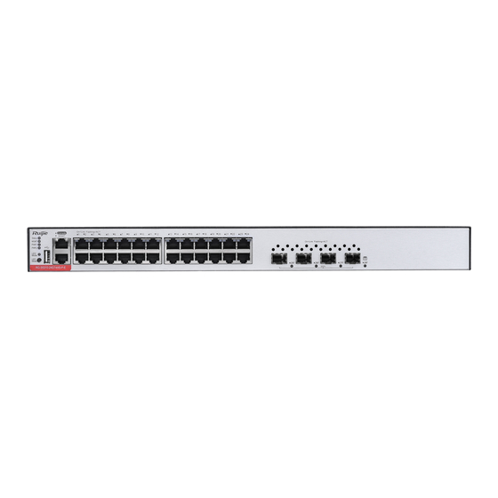
- Page 8 Hardware Installation and Reference Guide Product Overview Front Panel Figure 1-2 Front Panel of RG-S5310-24GT4XS-E 1. System Status LED 7. Management Port 2. MGMT Port LED 8. 10/100/1000Base-T Ethernet Port 3. PWR1 Status LED 9. 10GE SFP+ Port 4. PWR2 Status LED 10.
- Page 9 Hardware Installation and Reference Guide Product Overview Cooling The RG-S5310-24GT4XS-E switch adopts a left-to-right and front-to-right airflow to ensure normal operation. Maintain a minimum clearance of 100 mm (3.94 in.) around the device for air circulation. Figure 1-4 Airflow Direction Function Panel ID Color...
-
Page 10: Rg-S5300-24Gt2Sfp2Xs-E
SFP+ Modules, SFP+ Cables and SFP BIDI Modules. Type See Chapter 7 for details. The module types may update without prior notification. Please contact Ruijie Networks for details. AC Input Rated Voltage Range: 100 V AC to 240 V AC... - Page 11 Hardware Installation and Reference Guide Product Overview Storage Humidity 5% to 95% RH (non-condensing) Fan Speed Control Fan Fault Alarming Temperature Alarming Supported EMI Certification GB9254-2008CLASS A Safety Regulation GB4943-2011 Compliance Dimensions (W x D x H) 442 mm x 220 mm x 43.6 mm (17.40 in. x 8.66 in. x 1.72 in.) Weight 2.7 kg (5.95 lbs.) Appearance...
- Page 12 Hardware Installation and Reference Guide Product Overview 1. System Status LED 7. GE SFP Port 2. MGMT Port LED 8. GE SFP Port LED 3. USB Port 9. 10GE SFP+ Port 4. Console Port 10. 10GE SFP+ Port LED 5. Management Port 6.
-
Page 13: Rg-S5300-24Gt4Xs-E N/A
SFP+ Modules, SFP+ Cables and SFP+ BIDI Modules. SFP Module Type See Chapter 7 for details. The module types may update without prior notification. Please contact Ruijie Networks for details. AC Input Rated Voltage Range: 100 V AC to 240 V AC... - Page 14 Hardware Installation and Reference Guide Product Overview Rated Current Per Circuit: 1.5 A 10GBase-R Capable SFP+ Port 1000Base-X Capable Supported Not supported Power Consumption < 40 W 0ºC to 45ºC (32ºF to 113 ºF) at a height below 1800 m (1.12 miles) above the sea level At a height ranging from 1800 m (1.12 miles) to 5000 m (3.11 miles) above the sea level, the maximum Operating Temperature operating temperature decreases by 1°C (1.8°F) every time the altitude increases by 220 m (721.78...
- Page 15 Hardware Installation and Reference Guide Product Overview Figure 1-10 Front Panel of RG-S5300-24GT4XS-E 1. System Status LED 7. 10GE SFP+ Port 2. Management Port LED 8. Port LED 3. USB Port 4. Console Port 5. Management Port 6. 10/100/1000Base-T Ethernet Port Back Panel Figure1-11 Back Panel of RG-S5300-24GT4XS-E...
-
Page 16: Rg-S5310-48Gt4Xs-E N/A
Hardware Installation and Reference Guide Product Overview Function Panel ID Color Status System is not powered on. Blinking Green (3 System is being initialized. Continuous blinking indicates a fault. Blinking Green System is being located. (10 Hz) System Status LED Status Solid Green System is operating normally. - Page 17 Hardware Installation and Reference Guide Product Overview The module types may update without prior notification. Please contact Ruijie Networks for details. Power Supply Module Slots RG-PA70IB AC Input Rated Voltage Range: 100 V AC to 240 V AC Maximum Voltage Range: 90 V AC to 264 V AC...
- Page 18 Hardware Installation and Reference Guide Product Overview (W x D x H) Weight 4.3 kg (9.48 lbs.) Appearance The front panel of the RG-S5310-48GT4XS-E Ethernet switch provides 48 10/100/1000Base-T Ethernet ports, four 10GE SFP+ ports, one management port, one Console port and one USB port. The back panel has two power supply module slots. Figure 1-13 RG-S5310-48GT4XS-E Switch Appearance Front Panel Figure 1-14 Front Panel of RG-S5310-48GT4XS-E...
- Page 19 Hardware Installation and Reference Guide Product Overview 1. Grounding Stud 2. Power Supply Module Slot 1 (A filler panel is required if the slot is vacant.) 3. Power Supply Module Slot 2 (A filler panel is required if the slot is vacant.) Power Supply The RG-S5310-48GT4XS-E switch supports dual power supply modules.
-
Page 20: Rg-S5300-48Gt2Sfp2Xs-E
SFP+ Modules, SFP+ Cables and SFP+ BIDI Modules. See Chapter 7 for details. The module types may update without prior notification. Please contact Ruijie Networks for details. AC Input Rated Voltage Range: 100 V AC to 240 V AC... - Page 21 Hardware Installation and Reference Guide Product Overview 10GBase-R Capable SFP+ Port 1000Base-X Capable Supported Not supported Power Consumption < 55 W 0ºC to 45ºC (32ºF to 113 ºF) at a height below 1800 m (1.12 miles) above the sea level At a height ranging from 1800 m (1.12 miles) to 5000 m (3.11 miles) above the sea level, the maximum Temperature operating temperature decreases by 1°C (1.8°F) every time the altitude increases by 220 m (721.78...
- Page 22 Hardware Installation and Reference Guide Product Overview 1. System Status LED 7. GE SFP Port 2. Management Port LED 8. GE SFP Port LED 3. USB Port 9. 10GE SFP+ Port LED 4. Console Port 10. 10GE SFP+ Port 5. Management Port 6.
- Page 23 Hardware Installation and Reference Guide Product Overview Function Panel ID Color Status System is not powered on. Blinking Green System is being initialized. Continuous blinking (3 Hz) indicates a fault. Blinking Green System is being located. (10 Hz) System Status LED Status Solid Green System is operating normally.
-
Page 24: Rg-S5300-48Gt4Xs-E N/A
SFP+ Modules, SFP+ Cables and SFP+ BIDI Modules. SFP Module Type See Chapter 7 for details. The module types may update without prior notification. Please contact Ruijie Networks for details. AC Input Rated Voltage Range: 100 V AC to 240 V AC ... - Page 25 Hardware Installation and Reference Guide Product Overview (W x D x H) Weight 3 kg (6.61 lbs.) Appearance The front panel of the RG-S5300-48GT4XS-E switch provides 48 10/100/1000Base-T Ethernet ports, four 10GE SFP+ ports, one management port, one Console port and one USB port. The back panel has an AC power plug. Figure 1-21 RG-S5300-48GT4XS-E Switch Appearance Front Panel Figure 1-22 Front Panel of RG-S5300-48GT4XS-E...
- Page 26 Hardware Installation and Reference Guide Product Overview 1. Grounding Stud 2. AC Power Plug Power Supply The RG-S5300-48GT4XS-E switch has a built-in power supply module. The back panel has an AC power plug. Cooling The RG-S5300-48GT4XS-E switch adopts a left-to-right and front-to-right airflow to ensure normal operation. Maintain a minimum clearance of 100 mm (3.94 in.) around the device for air circulation.
-
Page 27: Rg-S5310-24Gt4Xs-P-E N/A
SFP Modules and SFP BIDI Modules SFP+ Modules, SFP+ Cables and SFP+ BIDI Modules. SFP Module Type See Chapter 7 for details. The module types may update without prior notification. Please contact Ruijie Networks for details. Power Supply Module Slots RG-PA600I-P-F... - Page 28 Hardware Installation and Reference Guide Product Overview 10GBase-R Capable SFP+ Port 1000Base-X Capable Supported All RJ45 ports are PoE+ capable and each port provides up to 30 W of power. The maximum power depends on the configured power supply. The PoE+ port is compliant with both the PoE (IEEE802.3af) and PoE+ (IEEE802.3at) standards. The maximum number of PoE devices supported by the switch is determined by the available PoE consumption of the switch and the actual PoE consumption of each device.
- Page 29 Hardware Installation and Reference Guide Product Overview Front Panel Figure 1-26 Front Panel of RG-S5310-24GT4XS-P-E 1. System Status LED 7. USB Port 2. Management Port LED 8. Console Port 3. PWR1 Status LED 9. Management Port 4. PWR2 Status LED 10.
- Page 30 Hardware Installation and Reference Guide Product Overview Cooling The RG-S5310-24GT4XS-P-E switch adopts a left-to-right and front-to-right airflow to ensure normal operation. Maintain a minimum clearance of 100 mm (3.94 in.) around the device for air circulation. Figure 1-28 Airflow Direction Function Panel ID Color...
- Page 31 SFP+ Modules, SFP+ Cables and SFP+ BIDI Modules. See Chapter 7 for details. The module types may update without prior notification. Please contact Ruijie Networks for details. AC Input Rated Voltage Range: 100 V AC to 240 V AC...
- Page 32 Hardware Installation and Reference Guide Product Overview 10GBase-R Capable SFP+ Port 1000Base-X Capable Supported All RJ45 ports are PoE+ capable and each port provides up to 30 W of power. Maximum PoE Output: 370 W The PoE+ port is compliant with both the PoE (IEEE802.3af) and PoE+ (IEEE802.3at) standards. The maximum number of PoE devices supported by the switch is determined by the available PoE consumption of the switch and the actual PoE consumption of each device.
- Page 33 Hardware Installation and Reference Guide Product Overview Front Panel Figure 1-30 Front Panel of RG-S5300-24GT2SFP2XS-P-E 1. System Status LED 7. Management Port 2. Management Port LED 8. 10/100/1000Base-T Ethernet Port 3. LED Mode Indicator 9. GE SFP Port 4. LED Mode Button 10.
- Page 34 Hardware Installation and Reference Guide Product Overview Figure 1-32 Airflow Direction Function Panel ID Color Status System is not powered on. Blinking Green (3 System is being initialized. Continuous blinking indicates a fault. Blinking Green (10 System is being located. System Status LED Status Solid Green...
-
Page 35: Rg-S5300-24Gt4Xs-P-E N/A
SFP+ Modules, SFP+ Cables and SFP+ BIDI Modules. SFP Module Type See Chapter 7 for details. The module types may update without prior notification. Please contact Ruijie Networks for details. AC Input Rated Voltage Range: 100 V AC to 240 V AC... - Page 36 Hardware Installation and Reference Guide Product Overview With PoE Full Load: < 410 W 0ºC to 45ºC (32ºF to 113 ºF) at a height below 1800 m (1.12 miles) above the sea level At a height ranging from 1800 m (1.12 miles) to 5000 m (3.11 miles) above the sea level, the maximum Operating Temperature operating temperature decreases by 1°C (1.8°F) every time the altitude increases by 220 m (721.78 ft.).
- Page 37 Hardware Installation and Reference Guide Product Overview 1. System Status LED 7. Management Port 2. Management Port LED 8. 10/100/1000Base-T Ethernet Port 3. LED Mode Indicator 9. 10GE SFP+ Port 4. LED Mode Button 10. Port LED 5. USB Port 6.
- Page 38 Hardware Installation and Reference Guide Product Overview Solid Green System is operating normally. The temperature at the air intake and exhaust vents Solid Yellow exceeds the threshold. 1. The temperature at the air intake and exhaust vents Solid Red exceeds the threshold greatly. 2.
- Page 39 Hardware Installation and Reference Guide Product Overview SFP+ Modules, SFP+ Cables and SFP+ BIDI Modules. See Chapter 7 for details. The module types may update without prior notification. Please contact Ruijie Networks for details. Power Supply Module Slots RG-PA600I-P-F...
- Page 40 Hardware Installation and Reference Guide Product Overview Operating Height 0 to 5000 m (3.11 miles) above the sea level 5% to 90% RH 5% to 95% RH (non-condensing) Fan Speed Control Fan Fault Alarming Temperature Alarming Supported EMI Certification GB9254-2008CLASS A Safety Regulation GB4943-2011...
- Page 41 Hardware Installation and Reference Guide Product Overview Back Panel Figure 1-39 Back Panel of RG-S5310-48GT4XS-P-E 1. Grounding Stud 2. Power Supply Module Slot 1 (A filler panel is required if the slot is vacant.) 3. Power Supply Module Slot 2 (A filler panel is required if the slot is vacant.) Power Supply The RG-S5310-48GT4XS-P-E switch supports dual power supply modules.
- Page 42 Hardware Installation and Reference Guide Product Overview The temperature at the air intake and exhaust vents Solid Yellow exceeds the threshold. 1. The temperature at the air intake and exhaust Solid Red vents exceeds the threshold greatly. 2. The system is not functioning properly. The power supply module is not seated.
-
Page 43: Rg-S5310-24Sfp4Xs-E N/A
SFP Modules and SFP BIDI Modules SFP Module Type SFP+ Modules, SFP+ Cables and SFP+ BIDI Modules. See Chapter 7 for details. The module types may update without prior notification. Please contact Ruijie Networks for details. Power Supply Module Slots RG-PA70IB... - Page 44 Hardware Installation and Reference Guide Product Overview 1000Base-X Capable supported Not supported Power Consumption < 85 W 0ºC to 45ºC (32ºF to 113 ºF) at a height below 1800 m (1.12 miles) above the sea level At a height ranging from 1800 m (1.12 miles) to 5000 m (3.11 miles) above the sea level, the maximum Operating Temperature operating temperature decreases by 1°C (1.8°F) every time the altitude increases by 220 m (721.78 ft.).
- Page 45 Hardware Installation and Reference Guide Product Overview 1. System Status LED 7. Management Port 2. Management Port LED 8. GE SFP Port 3. PWR1 Status LED 9. GE SFP Port LED 4. PWR2 Status LED 10. 10GE SFP+ Port 5. USB Port 11.
- Page 46 Hardware Installation and Reference Guide Product Overview Function Panel ID Color Status System is not powered on. Blinking Green (3 System is being initialized. Continuous blinking indicates a fault. Blinking Green System is being located. (10 Hz) System Status LED Status Solid Green System is operating normally.
-
Page 47: Rg-S5310-48Sfp4Xs-E N/A
SFP Module Type SFP Modules, SFP BIDI Modules SFP+ Modules, SFP+ Cables and SFP+ BIDI Modules. See Chapter 7 for details. The module types may update without prior notification. Please contact Ruijie Networks for details. Power Supply Module Slots ... - Page 48 Hardware Installation and Reference Guide Product Overview Storage Temperature -40ºC to 70ºC (-40ºF to 158ºF) Operating Humidity 10% to 90% RH (non-condensing) Operating Height 0 to 5000 m (3.11 miles) above the sea level Storage Humidity 5% to 95% RH (non-condensing) Fan Speed Control Fan Fault Alarming Temperature Alarming...
- Page 49 Hardware Installation and Reference Guide Product Overview Back Panel Figure 1-47 Back Panel of RG-S5310-48SFP4XS-E 1. Grounding Stud 2. Power Supply Module Slot 1 (A filler panel is required if the slot is vacant.) 3. Power Supply Module Slot 2 (A filler panel is required if the slot is vacant.) Power Supply The RG-S5310-48SFP4XS-E switch supports dual power supply modules.
- Page 50 Hardware Installation and Reference Guide Product Overview The temperature at the air intake and exhaust vents Solid Yellow exceeds the threshold. 1. The temperature at the air intake and exhaust vents Solid Red exceeds the threshold greatly. 2. The system is not functioning properly. The power supply module is not seated.
- Page 51 Hardware Installation and Reference Guide Product Overview HVDC Input: 240 V DC Maximum Input Voltage AC Input: 90 V AC to 264 V AC, 47 Hz/63 Hz Range HVDC Input: 192 VDC to 288 VDC Maximum Input Current Output Voltage 12 V Maximum Output Current 5.83 A...
- Page 52 Hardware Installation and Reference Guide Product Overview Item Specification Power Supply Model RG-PA150IB-F Switch Model RG-S5310-48SFP4XS-E AC Input: 100 V AC to 240 V AC, 50 Hz/60 Hz Rated Input Voltage Range HVDC Input: 240 V DC Maximum Input Voltage AC Input: 90 V AC to 264 V AC, 47 Hz/63 Hz Range HVDC Input: 192 V DC to 288 V DC...
- Page 53 Hardware Installation and Reference Guide Product Overview The switch can be powered on by either one power supply module or dual power supply modules. If both power supply modules are used, the switch works in the power redundancy mode. At least one power supply module is required. If any slot is unoccupied, install a filler panel to enable proper airflow. Specifications Item Specification...
- Page 54 Hardware Installation and Reference Guide Product Overview 1.13.4 RG-PA600I-P-F Module The RG-S5310-24GT4XS-P-E and RG-S5310-48GT4XS-P-E switches support the RG-PA600I-P-F power module. The RG-PA600I-P-F is an AC module (AC/HVDC input and DC output) providing an output voltage of 56 V and an output power of up to 600 W (PoE power: 370 The switch can be powered on by either one power supply module or dual power supply modules.
- Page 55 Hardware Installation and Reference Guide Product Overview Alarming When a power fault occurs, the output status LED turns off. Function Color Status The power supply module is not connected with a power cord. A power output error occurs, including fan fault, output Output Status LED short-circuit, output overcurrent protection, output Solid Red...
- Page 56 Hardware Installation and Reference Guide Product Overview Features Benefit Conformal Coating Moisture-proof, salt spray-proof, mold-proof, insulation-proof and leak-proof Undervoltage protection, output overcurrent protection, output overvoltage protection and output Protection short circuit protection I2C Communication The switch can communicate with the power supply module through I2C. System supports 1+1 power redundancy when the PoE power consumption is less than 370 W.
- Page 57 Hardware Installation and Reference Guide Product Overview 16.61 A (Input Voltage: 90 V AC to 176 V AC, 176 V AC not included) 1000 W (Input Voltage: 176 V AC to 290 V AC or 190 V DC to 290 V DC) Maximum Output Power 930 W (Input Voltage: 90 V AC to 176 V AC, 176 V AC not included) PoE Power Consumption...
- Page 58 Hardware Installation and Reference Guide Preparing for Installation 2 Preparing for Installation 2.1 Safety Precautions To avoid personal injury and device damage, carefully read the safety precautions before you install the switch. The following safety precautions may not cover all possible dangers. 2.1.1 General Safety Precautions ...
- Page 59 Hardware Installation and Reference Guide Preparing for Installation mA rated action current supports no more than eight power supplies. In this case, the 16 power supplies in the system require at least two leakage protectors with 30 mA rated action current and each leakage protector supports eight power supplies. If power supplies in a system differ in models, the rated leakage action current of each leakage protector divided by two is greater than the sum of maximum leakage currents of all the power supplies.
- Page 60 Hardware Installation and Reference Guide Preparing for Installation Too high temperatures can accelerate the aging of insulation materials, greatly reducing the reliability of the switch and severely affecting its service life. Temperature and Humidity Temperature Relative Humidity 0ºC to 45ºC (32ºF to 113ºF) 10% to 90% (non-condensing) The ambient temperature and humidity of the switch are measured at the point that is 1.5 m (59.06 in.) above the floor and 0.4 m (15.75 in.) before the switch rack when there is no protective plate in front or at the back of the rack...
- Page 61 Hardware Installation and Reference Guide Preparing for Installation 2.2.5 Grounding Requirements A proper grounding system is the basis for stable and reliable running and is indispensable for preventing lightning strikes and interference. Carefully check the grounding conditions at the installation site according to the grounding specifications, and complete grounding properly based on the actual situation.
- Page 62 Hardware Installation and Reference Guide Preparing for Installation Electromagnetic interference (EMI) occurs due to electromagnetic radiation or conduction, depending on the transmission path. When the energy, often RF energy, from a component arrives at a sensitive component via the space, the energy is known as radiated interference.
- Page 63 Hardware Installation and Reference Guide Installing the Switch 3 Installing the Switch Ensure that requirements in Chapter 2 are all met.
- Page 64 Hardware Installation and Reference Guide Installing the Switch 3.1 Installing Procedure Prepare for installation Prepare for installation Install the rack Mount the switch into the rack Ground the switch Install the modules Turn on the power Connect the cables Bundle the cables Verify the installation...
- Page 65 Hardware Installation and Reference Guide Installing the Switch 3.2 Before You Begin Confirm the following requirements before installation: The installation site provides sufficient space for heat dissipation. The installation site meets the temperature and humidity requirements of the switch. ...
- Page 66 Hardware Installation and Reference Guide Installing the Switch Figure 3-2 Installing Cage Nuts and Screws Secure the switch on the rack rails by tightening the screws. Figure 3-3 Tightening Screws Insert screws into the other two cage nuts and tighten them. Figure 3-4 Tightening Other Screws...
- Page 67 Hardware Installation and Reference Guide Installing the Switch 3.3.2 Mounting the Switch on the Wall All models of the RG-S5300-E series switches can be installed on the wall. All models of the RG-S5310-E series switches cannot be installed on the wall. Rotate the brackets by 90 degrees and secure the brackets to the switch by using the screws.
- Page 68 Hardware Installation and Reference Guide Installing the Switch 3.4 Installing and Removing a Power Supply Module Wear an anti-static wrist strap before the following operation. Installing the AC Power Supply Module Remove the module from its packing materials and make sure the input specifications meet requirements. Remove the blank filler panel in the empty slot.
- Page 69 Hardware Installation and Reference Guide Installing the Switch protective cover of the power input terminal, loosen the screw, and connect the terminals of the power cord. From left to right, they are blue and red, and then cover the terminal protective cover. Connect the other end of the power cord to the DC terminal block of the rack.
- Page 70 Hardware Installation and Reference Guide Installing the Switch Pull the module out of the slot gently. Install the filler panel in the empty slot to allow for adequate airflow. 3.5 Grounding the Switch Connect the PGND to the grounding lug of the rack and then connect the grounding lug to the grounding bar of the equipment room. Notes ...
- Page 71 Hardware Installation and Reference Guide Installing the Switch Insert the single-mode or multi-mode fiber into the corresponding interface according to the panel identification, and distinguish the transmitting and receiving ends of the fiber-optic cable. Insert the twisted pair cable with RJ45 connector into the corresponding interface according to the panel identification, and distinguish the crossover cable and the straight cable.
- Page 72 Hardware Installation and Reference Guide Verifying Operating Status 4 Verifying Operating Status 4.1 Setting up Configuration Environment Setting up Configuration Environment Connect the PC to the management port of the switch with an Ethernet cable. Figure 4-1 Configuring Environment Connecting an Ethernet Cable ...
- Page 73 Hardware Installation and Reference Guide Verifying Operating Status In the Name box, enter the new connection name and click OK. The Connect to dialog will appear. From the Connect using drop- down list, select a COM port to be used. Figure 4-3 Figure 4-3 Click OK.
- Page 74 Hardware Installation and Reference Guide Verifying Operating Status Click OK and the HyperTerminal window will appear. 4.2 Powering on Switch Checklist before Power-on The switch is fully grounded. The power cord is properly connected. The power cord retention clip secures the input power cord to the power supply. ...
- Page 75 Hardware Installation and Reference Guide Monitoring and Maintenance 5 Monitoring and Maintenance 5.1 Monitoring When the switch is running, you can monitor the module status by observing the module LED. If the SYS indicator is red, it indicates that the system is faulty. Log in to the web-based management system to troubleshoot the fault.
- Page 76 Hardware Installation and Reference Guide Monitoring and Maintenance Replacing Lithium Battery The device has a built-in lithium battery to maintain the real-time clock without external power to the switch. To replace the lithium battery, contact technical support personnel. Replacing the battery with the wrong type may cause explosion or danger. If the battery is damaged, please replace it with the same type.
- Page 77 Check the installation of other modules Check the LEDs on the device Check serial port connection and parameters Check the cable connection Contact Technical Support of Ruijie Networks 6.2 Troubleshooting Fault 1: The login password is forgotten. Symptom Failed to log into the system.
- Page 78 Check whether the configuration of the serial port on the HyperTerminal is consistent with that in Configuration Guide. If there is still no output on the serial port, please contact Ruijie technical support. Fault 4: The serial port console output is garbled.
- Page 79 Hardware Installation and Reference Guide Troubleshooting wavelength of 1310 nm cannot be connected to an SFP module of 1550 nm. Check whether the distance between the two sides exceeds the maximum length marked on the SFP module. Check whether the speeds of the two sides match and whether the optical fiber type meets requirements.
- Page 80 Hardware Installation and Reference Guide Appendix 7 Appendix 7.1 Connectors and Media 1000BASE-T/100BASE-TX/10BASE-T The 1000BASE-T/100BASE-TX/10BASE-T is a 10/100/1000 Mbps auto-negotiation port that supports auto MDI/MDIX Crossover. Compliant with IEEE 802.3ab, 1000BASE-T requires Category 5e 100-ohm UTP or STP (STP is recommended) with a maximum distance of 100 meters (328 feet).
- Page 81 Hardware Installation and Reference Guide Appendix Fiber Connection You can choose single mode or multimode fibers according to the module types. Figure 7- shows connection of fiber-optic cable. Figure 7-3 Fiber-Optic Cable Connection...
- Page 82 We provide appropriate SFP modules (Mini-GBIC modules) according to the port types. You can select the module to suit your specific needs. Besides, the Mini-GBIC-GT module is also supported. The following models and technical specifications of some SFP modules are listed for your reference. See Ruijie Transceiver Installation and Reference Guide for details. Table 7-2 Mini-GBIC (SFP) Models and Specifications...
- Page 83 Hardware Installation and Reference Guide Appendix SM1310 connector) MINI-GBIC-ZX50- SMF2 1550 SM1550 connector) MINI-GBIC-ZX80- SMF2 1550 SM1550 connector) MINI-GBIC-ZX100- SMF2 1550 SM1550 connector) Table 7-3 SFP Copper Module Standard 1000Base-T SFP Module Support DDM (Yes/No) 1000Base-T Mini-GBIC-GT Table 7-4 Cabling Specifications SFP Model Interface type Cable Type...
- Page 84 Hardware Installation and Reference Guide Appendix SM1550 MINI-GBIC- SMF2 (LC connector) 9/125 100 km ZX100-SM1550 SDH155-SFP-SX- MMF1 (MPO connector) 62.5/125 500 m MM850 SDH155-SFP-SX- MMF1 (MPO connector) 62.5/125 2 km MM1310 SDH155-SFP- SMF2 (LC connector) 9/125 15 km LH15-SM1310 SDH155-SFP- SMF2 (LC connector) 9/125 40 km...
- Page 85 We provide appropriate SFP+ modules according to the port types. You can select the module to suit your specific needs. The following models and technical specifications of some SFP+ modules are listed for your reference. See Ruijie Transceiver Installation and Reference Guide for details.
- Page 86 Hardware Installation and Reference Guide Appendix 400 (OM1) 66 m XG-SFP-SR- MMF1 (MPO connector) 50/125 2000 (OM3) 300 m SM1270-BIDI XG-SFP-SR- MMF1 (MPO connector) 50/125 2000 (OM3) 300 m SM1330-BIDI XG-SFP-LR- SMF2 (LC connector) 9/125 10 km SM1270-BIDI XG-SFP-LR- SMF2 (LC connector) 9/125 10 km SM1330-BIDI...
- Page 87 Hardware Installation and Reference Guide Appendix Speed/Distance Paring Models XG-SFP-SR-SM1270-BIDI 10-Gigabit/300 m XG-SFP-SR-SM1330-BIDI XG-SFP-LR-SM1270-BIDI 10-Gigabit/10 km XG-SFP-LR-SM1330-BIDI BIDI modules must be used in pairs. If XG-SFP-SR-SM1270-BIDI is used at one end, then XG-SFP-SR-SM1330-BIDI must be applied to the other end.
- Page 88 Hardware Installation and Reference Guide Appendix 7.4 Lightening Protection Installing AC Power Arrester (Lightning Protection Power Strip) The AC power port must be connected to an external lightning protection power strip to prevent the switch from being struck by lightning when the AC power cord is introduced from the outdoor and directly connected to the power port of the switch. The lightning protection power strip can be fixed on the rack, workbench, or wall in the equipment room by using cable ties and screws.
- Page 89 Hardware Installation and Reference Guide Appendix Tools: Phillips screwdrivers or flat-head screwdriver, multimeter, and diagonal pliers Installation Steps: Tear one side of the protective paper for the double-sided adhesive tape and paste the tape to the housing of the Ethernet port arrester.
- Page 90 Hardware Installation and Reference Guide Appendix 7.5 Cabling When the switch is installed in a standard 19-inch rack, secure the cables around the cable management brackets. Top cabling or bottom cabling is adopted according to the actual situation in the equipment room. All transferred cable connectors should be placed at the bottom of the rack in an orderly manner instead of outside the rack that is easy to touch.
- Page 91 Hardware Installation and Reference Guide Appendix The metal hole traversed by cables should have a smooth and fully rounding surface or an insulated lining. Use cable ties to bundle up cables properly. Please do not connect two or more cable ties to bundle up cables. ...
- Page 92 Hardware Installation and Reference Guide Appendix ① Flat washer ② Nut ③ Spring washer ④ Flat washer Hard power cords should be fastened in the terminal connection area to prevent stress on terminal connection and cable. Do not use self-tapping screws to fasten terminals. ...
- Page 93 Hardware Installation and Reference Guide Appendix Do not build the equipment room in the proximity of livestock farms. Otherwise, the machine room should be located on the windward side of the pollution source perennially. The previous livestock house or fertilizer warehouse cannot be used as the machine room.
Need help?
Do you have a question about the 5310-E Series and is the answer not in the manual?
Questions and answers