
Related Manuals for Ruijie RG-S5350-E Series


Summary of Contents for Ruijie RG-S5350-E Series
- Page 1 Ruijie RG-S5350-E Series Switches Hardware Installation and Reference Guide Document Version: V1.0 Date: July 9, 2024 Copyright © 2024 Ruijie Networks...
- Page 2 The content of this document is subject to constant change due to product version upgrades or other reasons. Thus, Ruijie Networks reserves the right to modify the content of the document without prior notice or prompt. This manual serves solely as a user guide. While Ruijie Networks endeavors to ensure the accuracy and reliability of the content when compiling this manual, it does not guarantee that the content of the manual is free of errors or omissions.
- Page 3 Preface Intended Audience This document is intended for: Network engineers Technical support and servicing engineers Network administrators Technical Support Ruijie Networks website: https://www.ruijienetworks.com/ Online support center: https://ruijienetworks.com/support Case portal: https://caseportal.ruijienetworks.com Community: https://community.ruijienetworks.com ...
-
Page 4: Product Overviews
Product Overviews 1 Product Overviews The RG-S5350-E series switches are new generation layer 3 switches, providing high performance, consolidated security and multiple services. The switches are mainly applied to the access layer to provide line-rate switching and complete QoS policies, prioritizing some traffic over others to ensure important data transmission without lantency. The switches also support a wide variety of Ethernet interfaces with flexible media options for network construction. -
Page 5: Specifications
SFP+ Modules, SFP+ Cables and SFP+ BIDI Modules. SFP Module Type See Chapter 7 for details. The module types may update without prior notification. Please contact Ruijie Networks for details. AC Input Rated Voltage Range: 100 V AC to 240 V AC... -
Page 6: Front Panel
Hardware Installation and Reference Guide Product Overviews 5% ~ 95% RH Storage Humidity Fan Speed Control (manual configuration not supported) Fan Fault Alarming Temperature Supported Alarming EMI Certification GB/T 9254.1 Safety Regulation GB 4943.1 Compliance Dimensions 442mm × 220mm × 43.6mm (17.4in x 8.66in x 1.72in ) (W x D x H) 3kg (6.61 lbs.) (The product information label is on the bottom of the switch.) Weight... -
Page 7: Power Supply Module
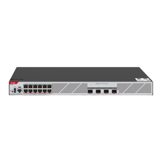
Hardware Installation and Reference Guide Product Overviews Note 1. System Status LED 5.Console Port 2.LED Mode LED 6 . 10/100/1000Base-T Ethernet 3.LED Mode button Port 4.USB Port 7.10GE SFP+ Port Back Panel Figure 1-2 Back Panel of RG-S5350-12GT4XS-P-E Note 1.AC Power Plug 2.Grounding Stud Power Supply Module The RG-S5350-12GT4XS-P-E switch has a built-in power supply module. - Page 8 Hardware Installation and Reference Guide Product Overviews Function Panel ID Color Status System is not powered on. Blinking System is being initialized. Continuous blinking Green (3 indicates a fault. Blinking Green (10 System is being located. System Status LED Status Solid System is operating normally.
- Page 9 SFP Modules and SFP BIDI Modules SFP+ Modules, SFP+ Cables and SFP+ BIDI Modules. See Chapter 7 for details. The module types may update without prior notification. Please contact Ruijie Networks SFP Module Type for details. When up to two SFP+ optical modules are configured with a maximum distance of 80 km (49.71 miles), the operating temperature range is 0º...
- Page 10 Hardware Installation and Reference Guide Product Overviews GB/T 9254.1 EMI Certification Safety Regulation GB 4943.1 Compliance Dimensions 442mm × 220mm × 43.6mm (17.4in x 8.66in x 1.72in ) (W x D x H) Weight 3kg (6.61 lbs.) (The product information label is on the bottom of the switch.) Appearance The front panel of the RG-S5350-24GT4XS-E...
-
Page 11: Back Panel
Hardware Installation and Reference Guide Product Overviews Note 1.System Status LED 4 . 10/100/1000Base-T Ethernet 2.USB Port Port 3.Console Port 5.10GE SFP+ Port Back Panel Figure 1-7 Back Panel of RG-S5350-24GT4XS-E Note 1.AC Power Plug 2.Grounding Stud Power Supply The RG-S5350-24GT4XS-E switch has a built-in power supply module. The back panel has an an AC power plug. Cooling The RG-S5350-24GT4XS-E uses natural heat dissipation to to ensure that the switch works properly in the specified environment. - Page 12 SFP+ Modules, SFP+ Cables and SFP+ BIDI Modules. SFP Module Type See Chapter 7 for details. The module types may update without prior notification. Please contact Ruijie Networks for details. AC Input Rated Voltage Range: 100 V AC to 240 V AC...
- Page 13 Hardware Installation and Reference Guide Product Overviews The PoE+ port is compliant with both the PoE (IEEE802.3af) and PoE+ (IEEE802.3at) standards. The maximum number of PoE devices supported by the switch is determined by the available PoE consumption of the switch and the actual PoE consumption of each device.
- Page 14 Hardware Installation and Reference Guide Product Overviews Front Panel Figure 1-9 Front Panel of RG-S5350-24GT4XS-P-E Note 1.System Status LED 5.Console\ Port 2.LED Mode LED 6 . 10/100/1000Base-T Ethernet 3.LED Mode button Port 4.USB Port 7.10GE SFP+ Port Back Panel...
- Page 15 Hardware Installation and Reference Guide Product Overviews Figure 1-10 Back Panel of RG-S5350-24GT4XS-P-E Note 1.AC power plug 2.Grounding Stud Power Supply The RG-S5350-24GT4XS-P-E switch has a built-in power supply module. The back panel has an an AC power plug. Cooling The RG-S5350-24GT4XS-P-E switch adopts a left-to-right and front-to-right airflow to ensure normal operation.
- Page 16 Hardware Installation and Reference Guide Product Overviews Yellow vents exceeds the threshold. 1. The temperature at the air intake and exhaust Solid Red vents well exceeds the threshold. 2. The system is not functioning properly. Solid The LED indicates the switching status. green LED Mode LED LED Mode...
- Page 17 Hardware Installation and Reference Guide Product Overviews See Chapter 7 for details. The module types may update without prior notification. Please contact Ruijie Networks for details. AC Input Rated Voltage Range: 100 V AC to 240 V AC Built-in Power Supply...
- Page 18 Hardware Installation and Reference Guide Product Overviews Front Panel Figure 1-13 Front Panel of RG-S5350-48GT4XS-E Note 1.System Status LED 4 . 10/100/1000Base-T Ethernet 2.USB Port Port 3.Console Port 5.10GE SFP+ Port Back Panel...
- Page 19 Hardware Installation and Reference Guide Product Overviews Figure 1-14 Back Panel of RG-S5350-48GT4XS-E Note 1.AC Power Plug 2.Grounding Stud Power Supply The RG-S5350-48GT4XS-E switch has a built-in power supply module. The back panel has an AC power plug. Cooling The RG-S5350-48GT4XS-E switch adopts a left-to-right and front-to-right airflow to ensure normal operation. Maintain a minimum clearance of 100 mm (3.94 in.) around the device for air circulation.
- Page 20 SFP+ Modules, SFP+ Cables and SFP+ BIDI Modules. SFP Module Type See Chapter 7 for details. The module types may update without prior notification. Please contact Ruijie Networks for details. AC Input Rated Voltage Range: 100 V AC to 240 V AC...
- Page 21 Hardware Installation and Reference Guide Product Overviews The PoE+ port is compliant with both the PoE (IEEE802.3af) and PoE+ (IEEE802.3at) standards. The maximum number of PoE devices supported by the switch is determined by the available PoE consumption of the switch and the actual PoE consumption of each device.
- Page 22 Hardware Installation and Reference Guide Product Overviews Front Panel Figure 1-17 Front Panel of RG-S5350-48GT4XS-P-E Note 1.System Status LED 5.Console Port 2.LED Mode LED 6 . 10/100/1000Base-T Ethernet 3.LED Mode button Port 4.USB Port 7.10GE SFP+ Port...
- Page 23 Hardware Installation and Reference Guide Product Overviews Back Panel Figure 1-18 Back Panel of RG-S5350-48GT4XS-P-E Note 1.AC Power Plug 2.Grounding Stud Power Supply The RG-S5350-48GT4XS-P-E switch has a built-in power supply module. The back panel has an AC power plug. Cooling The RG-S5350-48GT4XS-P-E switch adopts a left-to-right and front-to-right airflow to ensure normal operation.
-
Page 24: Preparing For Installation
Hardware Installation and Reference Guide Preparing for Installation Green Solid The temperature at the air intake and exhaust Yellow vents exceeds the threshold. 1. The temperature at the air intake and exhaust Solid Red vents well exceeds the threshold. 2. The system is not functioning properly. Solid The LED indicates the switching status. -
Page 25: General Safety Precautions
Hardware Installation and Reference Guide Preparing for Installation 2.1.1 General Safety Precautions Keep the chassis clean, free from any dust. Do not place the device in walking areas. During the installation and maintenance, do not wear loose clothes, ornaments, or any other things that may be hooked by the chassis. -
Page 26: Installation Environment Requirements
Hardware Installation and Reference Guide Preparing for Installation To guarantee personal safety, the rated leakage action current of each leakage protector in the system must be equal to or less than 30 mA (human body safety current is 30 mA). When twice of the total leakage current of the system is greater than 30 mA, the system must be equipped with two or more leakage protectors. -
Page 27: Temperature/Humidity Requirements
Hardware Installation and Reference Guide Preparing for Installation 2.1.8 Temperature/Humidity Requirements To ensure the normal operation and prolonged service life of the switch, maintain an appropriate temperature and humidity in the equipment room. The equipment room with too high or too low temperature and humidity for a long period may damage the switch. -
Page 28: Grounding Requirements
Hardware Installation and Reference Guide Preparing for Installation circuit in the device to eliminate interference from the power grid. The switch should be located far away from the large power radio launch pad, radar launch pad, and high-frequency large-current devices. ... -
Page 29: Lightning Protection Requirements
Special Tools ESD gloves, wire stripper, crimping plier, RJ45 crimping plier, and wire cutter Cleaning Tools Dust-free paper, fiber end-face microscope Meters Multimeter, bit error rate tester (BERT), optical power meter No tool kit is delivered with the RG-S5350-E series switches. -
Page 30: Installing The Switch
Hardware Installation and Reference Guide Installing the Switch 3 Installing the Switch The RG-S5350-E series multi-GE switches must be installed indoors. Ensure that requirements in Chapter 2 are all met. Installing Procedure Prepare for installation Mount the switch into the rack... -
Page 31: Mounting The Switch In A Rack
3.1.1 Mounting the Switch in a Rack All models of the RG-S5350-E series switches can be installed in a standard 19-in. four-post EIA rack. Mount the switch in the rack with the front panel face forward. - Page 32 Hardware Installation and Reference Guide Installing the Switch Secure the switch on the rack rails by tightening the screws. Figure 3-3 Tightening Screws Insert screws into the other two cage nuts and tighten them. Figure 3-4 Tightening Other Screws...
-
Page 33: Installing The Switch On A Workbench
Place the switch on the workbench to allow for adequate airflow. 3.1.3 Mounting the Switch on the Wall The switch comes with mounting brackets. The RG-S5350-E series supports wall-mounting. The installation process is as follows. Rotate the brackets by 90 degrees and secure the brackets to the switch by using the screws. -
Page 34: Grounding The Switch
Hardware Installation and Reference Guide Installing the Switch Grounding the Switch Connect the PGND to the grounding lug of the rack and then connect the grounding lug to the grounding bar of the equipment room. Notes The sectional area of the grounding wire should be determined according to the possible maximum current. Cables of good conductor should be used. -
Page 35: Verifying Installation
Hardware Installation and Reference Guide Verifying Operating Status The power cords and other cables should be bundled in a visually pleasing way. When you bundle fibers, make sure that the fibers at the connectors have natural bends or bends of large radius. ... -
Page 36: Connecting An Ethernet Cable
Hardware Installation and Reference Guide Verifying Operating Status Connecting an Ethernet Cable Plug the crystal head of the Ethernet cable into the network port of the PC. Connect the RJ-45 end to the Console port on your AC. Setting Parameters ... - Page 37 Hardware Installation and Reference Guide Verifying Operating Status Select Serial, and enter the serial port in Serial line and baud rate in Speed. Fugure 4-3...
- Page 38 Hardware Installation and Reference Guide Verifying Operating Status Select Serial. The serial port parameter setting page is displayed. Set Speed to 9600, Data bits to 8, Stop bits to 1, Parity to None, and Flow control to None. Figure 4-4 Click Open and the HyperTerminal window will appear.
-
Page 39: Powering On Switch
Hardware Installation and Reference Guide Monitoring and Maintenance Powering on Switch Checklist before Power-on The switch is fully grounded. The power cord is properly connected. The power cord retention clip secures the input power cord to the power supply. ... -
Page 40: Cooling System Maintenance
Hardware Installation and Reference Guide Monitoring and Maintenance Fan and power supply status System temperature For the monitoring commands, see RG-S5350-E Series Switches Configuration Guide. Maintenance Cooling System Maintenance If the fan module fails, an alarm will be generated. ... -
Page 41: Troubleshooting Flowchart
Check the installation of other modules Check the LEDs on the device Check serial port connection and parameters Check the cable connection Contact Technical Support of Ruijie Networks Troubleshooting Fault 1: The login password is forgotten. Symptom Failed to log into the system. - Page 42 Check whether the configuration of the serial port on the HyperTerminal is consistent with that in Configuration Guide. If there is still no output on the serial port, please contact Ruijie technical support. Fault 4: The serial port console output is garbled.
- Page 43 Hardware Installation and Reference Guide Appendix Check whether the receiving end and transmitting end are reversed. The transmitting end of a fiber port must be connected to the corresponding receiver at the other end. You can confirm both ends by exchanging the connection order of two fiber-optic cables.
-
Page 44: Fiber Connection
Hardware Installation and Reference Guide Appendix 10BASE-T uses Category 3, 4, 5 100-ohm UTP/STP and 1000BASE-T uses Category 5 100-ohm UTP/STP for connections. Both support a maximum length of 100 meters. Table 7- shows 100BASE-TX/10BASE-T pin assignments. Table 7- 1 100BASE-TX/10BASE-T Pin Assignments Socket Plug Input Receive Data+... -
Page 45: Mini-Gbic Modules
We provide appropriate SFP modules (Mini-GBIC modules) according to the port types. You can select the module to suit your specific needs. Besides, the Mini-GBIC-GT module is also supported. The following models and technical specifications of some SFP modules are listed for your reference. See Ruijie Transceiver Installation and Reference Guide for details. - Page 46 Hardware Installation and Reference Guide Appendix MINI-GBIC-LH40- SMF2 (LC 1310 SM1310 connector) MINI-GBIC-ZX50- SMF2 (LC 1550 SM1550 connector) MINI-GBIC-ZX80- SMF2 (LC 1550 SM1550 connector) MINI-GBIC-ZX100- SMF2 (LC 1550 SM1550 connector) Table 7-3 SFP Copper Module Standard 1000Base-T SFP Module Support DDM (Yes/No) 1000Base-T Mini-GBIC-GT Table 7-4 Cabling Specifications...
- Page 47 Hardware Installation and Reference Guide Appendix MINI-GBIC- SMF2 (LC connector) 9/125 80 km ZX80-SM1550 MINI-GBIC- SMF2 (LC connector) 9/125 100 km ZX100-SM1550 SDH155-SFP- MMF1 (MPO connector) 62.5/125 500 m SX-MM850 SDH155-SFP- MMF1 (MPO connector) 62.5/125 2 km SX-MM1310 SDH155-SFP- SMF2 (LC connector) 9/125 15 km LH15-SM1310...
-
Page 48: Sfp Modules
We provide appropriate SFP+ modules according to the port types. You can select the module to suit your specific needs. The following models and technical specifications of some SFP+ modules are listed for your reference. See Ruijie Transceiver Installation and Reference Guide for details. - Page 49 Hardware Installation and Reference Guide Appendix 2000 (OM3) 300 m 50/125 500 (OM2) 82 m 400 (OM1) 66 m XG-SFP-SR- MMF1 (MPO connector) 50/125 2000 (OM3) 300 m SM1270-BIDI XG-SFP-SR- MMF1 (MPO connector) 50/125 2000 (OM3) 300 m SM1330-BIDI XG-SFP-LR- SMF2 (LC connector) 9/125 10 km...
- Page 50 Hardware Installation and Reference Guide Appendix Table 7-9 Pairing Models of the 10-Gigabit BIDI Module Speed/Distance Paring Models XG-SFP-SR-SM1270-BIDI 10-Gigabit/300 m XG-SFP-SR-SM1330-BIDI XG-SFP-LR-SM1270-BIDI 10-Gigabit/10 km XG-SFP-LR-SM1330-BIDI BIDI modules must be used in pairs. If XG-SFP-SR-SM1270-BIDI is used at one end, then XG-SFP-SR-SM1330- BIDI must be applied to the other end.
-
Page 51: Lightening Protection
Hardware Installation and Reference Guide Appendix Lightening Protection Installing AC Power Arrester (Lightning Protection Power Strip) The AC power port must be connected to an external lightning protection power strip to prevent the switch from being struck by lightning when the AC power cord is introduced from the outdoor and directly connected to the power port of the switch. - Page 52 Hardware Installation and Reference Guide Appendix Please connect an Ethernet port arrester to the switch to prevent the damage by lightning before connecting an outdoor Ethernet cable to the switch. Tools: Phillips screwdrivers or flat-head screwdriver, multimeter, and diagonal pliers Installation Steps: Tear one side of the protective paper for the double-sided adhesive tape and paste the tape to the housing of the Ethernet port arrester.
- Page 53 Hardware Installation and Reference Guide Appendix grounding. Incomplete arrester installation. If there is more than one port connected to the peer device on the switch, arresters need to be installed on all connection ports for the purpose of lightning protection.
- Page 54 Hardware Installation and Reference Guide Appendix Cabling When the switch is installed in a standard 19-inch rack, secure the cables around the cable management brackets. Top cabling or bottom cabling is adopted according to the actual situation in the equipment room. All transferred cable connectors should be placed at the bottom of the rack in an orderly manner instead of outside the rack that is easy to touch.
- Page 55 Hardware Installation and Reference Guide Appendix Cables of different types (such as power cords, signal cables, and ground cables) should be separated in cabling and bundling. Mixed bundling is disallowed. When they are close to each other, it is recommended to adopt crossover cabling.
- Page 56 Hardware Installation and Reference Guide Appendix Cables not to be assembled or remaining parts of cables should be folded and placed in a proper position of the rack or cable trough. The proper position refers to a position that does not affect device running or damage the switch or cable.
-
Page 57: Site Selection
Hardware Installation and Reference Guide Appendix Do not use self-tapping screws to fasten terminals. Power cords of the same type and in the same cabling direction should be bundled up into cable bunches, with cables in cable bunches clean and straight. ... - Page 58 Hardware Installation and Reference Guide Appendix for flame retarding, soundproofing, heat absorption, dust reduction, and electromagnetic shielding. Keep the door and the window closed to make the machine room sealed. The steel door is recommended for soundproofing. Sulfur-containing materials are forbidden.
Need help?
Do you have a question about the RG-S5350-E Series and is the answer not in the manual?
Questions and answers