Table of Contents
Advertisement
Quick Links
Advertisement
Table of Contents

Related Manuals for Ruijie RG-S5750-S Series


Summary of Contents for Ruijie RG-S5750-S Series
- Page 1 RG-S5750-S Series Switch Hardware Installation and Reference Guide V1.15...
-
Page 2: Copyright Statement
This document is provided “as is”. The contents of this document are subject to change without any notice. Please obtain the latest information through the Ruijie Networks website. Ruijie Networks endeavors to ensure content accuracy and will not shoulder any responsibility for losses and damages caused due to content omissions, inaccuracies or errors. -
Page 3: Obtaining Technical Assistance
It is intended for the users who have some experience in installing and maintaining network hardware. At the same time, it is assumed that the users are already familiar with the related terms and concepts. Obtaining Technical Assistance Ruijie Networks website: http://www.ruijienetworks.com/ http://webchat.ruijie.com.cn ... -
Page 4: Chapter 1 Product Overview
Chapter 1 Product Overview The RG-S5750-S series switches are the next generation Layer 3 switches introduced by Ruijie Networks. Featuring high performance, reliable security, and multiple services, the RG-S5750-S series switches are mainly applicable to the convergence layer of large-scale networks to provide full wire-speed exchanging and complete QoS services, classify different services according to different business needs and ensure the prompt transmission of key data. - Page 5 Mini-GBIC-GT The supported module type may change at any time. For the detailed change information, consult the Ruijie Networks. The Bi-Directional (BIDI) optical modules must be used in pairs. For details about the pairs of BIDI modules, see the Appendix B.
-
Page 6: Product Appearance
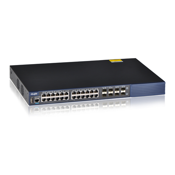
RG-S5750-24GT/8SFP-S switch is a class A product. In a domestic environment, this product may cause radio interference in which case the user may be required to take adequate measures. Product Appearance The front panel of the RG-S5750-24GT/8SFP-S Ethernet switch provides twenty four 10/100/1000Base-T Ethernet ports, eight 1000M SFP fiber/copper combo ports, one Console port and one USB port. -
Page 7: Power Supply System
At present, the redundant power supply interface can be used together with the RPS150 that are manufactured by Ruijie Networks. Unless otherwise stated, other power supply modules cannot be used for power input; otherwise, an abnormality may occur or damage the switch. -
Page 8: Led Indicators
LED Indicators Table1-4 Indicator Panel Identification Status Meaning Status indicator Status The switch is not powered on. Blinking green The switch is being initialized. If the blinking persists, however, it indicates that an abnormality occurs. Solid green The switch is operational. Solid yellow It indicates a warning on the switch temperature. -
Page 9: Technical Specifications
GE-SFP-LX20-SM1550-BIDI GE-SFP-LH40-SM1310-BIDI GE-SFP-LH40-SM1550-BIDI Mini-GBIC-ZX50 Mini-GBIC-ZX80 Mini-GBIC-ZX100 1000Base-T: Mini-GBIC-GT The supported module type may change at any time. For the detailed change information, consult the Ruijie Networks. The Bi-Directional (BIDI) optical modules must be used in pairs. For details about... - Page 10 the pairs of BIDI modules, see the Appendix B. Extended Module M5000E-02SFP/GT M5000E-01XS Type M5000E-02XS 100Base-X SFP Port 1000Base-X RG-RPS150 RPS Type Power Supply AC input: Rated voltage range: 100–240 V AC Maximum voltage range: 90–264 V AC Frequency: 50/60 Hz Rated current: 2 A HVDC input: Voltage range: 192–290 V DC...
- Page 11 The front panel of the RG-S5750-48GT/4SFP-S Ethernet switch provides 48 10/100/1000Base-T Ethernet ports, four 1000M SFP fiber/copper combo ports, one Console port and one USB port. The back panel provides AC power input ports, RPS input ports and two extension module slots. Figure 1-5 Appearance of the RG-S5750-48GT/4SFP-S Front Panel Figure 1-6 Schematic Diagram of the RG-S5750-48GT/4SFP-S Front Panel...
- Page 12 At present, the redundant power supply interface can be used together with the RPS150 that are manufactured by Ruijie Networks. Unless otherwise stated, other power supply modules cannot be used for power input; otherwise, an abnormality may occur or damage the switch.
- Page 13 LED Indicators Table1-6 Indicator Panel Identification Status Meaning Status indicator Status The switch is not powered on. Blinking green The switch is being initialized. If the blinking persists, however, it indicates that an abnormality occurs. Solid green The switch is operational. Solid yellow It indicates a warning on the switch temperature.
- Page 14 Mini-GBIC-GT The supported module type may change at any time. For the detailed change information, consult the Ruijie Networks. The Bi-Directional (BIDI) optical modules must be used in pairs. For details about the pairs of BIDI modules, see the Appendix B.
- Page 15 Current range: 0.5–0.24 A Max. Power Dual power supplies: 50 W (with extension modules); 34 W (without extension modules) Consumption Single power supply: 48 W (with extension modules); 33 W (without extension modules) Temperature Working temperature: 0–50ºC Storage temperature: -40–70ºC Humidity Working humidity: 10%–90% RH Storage humidity: 5%–90% RH...
- Page 16 Front Panel Figure 1-10 Schematic Diagram of the RG-S5750-24SFP/8GT-S Front Panel Note: 1. Switch status indicator 6. USB port 2. Power supply 1 status indicator 7. Console port 3. Power supply 2 status indicator 8. 100/1000Base-X SFP port 4. Extension port 1 status indicator 9.
- Page 17 Applicable Models RG-S5750-24SFP/8GT-S RG-S5750-24SFP/8GT-S Rated Input Voltage 100–240 VAC, 50/60 Hz 240 VDC Range Maximum Input 90–264 VAC, 50/60 Hz 192–290 VDC Voltage Range Power 60 W Power Supply Supported Hot-Plugging Power Supply 1+1 redundancy Redundancy Over-Voltage 13.4–16 V Protection Over-Current 6–12 A Protection...
- Page 18 LED Indicators Table1-9 Indicator Panel Identification Status Meaning Status indicator Status The switch is not powered on. Blinking green The switch is being initialized. If the blinking persists, however, it indicates that an abnormality occurs. Solid green The switch is operational. Solid yellow It indicates a yellow warning on the switch temperature.
- Page 19 Ruijie Networks for different transmission distances. This module supports one-meter or three-meter SFP Plus passive copper cable on the RG-S5750-S series switches. It can be used together with XG-SFP-CU1M and XG-SFP-CU3M copper cable transceiver modules of Ruijie Networks.
- Page 20 M5000E-01XS 1-port 10G interface module 1 SFP Plus port M5000E-02XS 2-port 10G interface module 2 SFP Plus ports The 1000Base-X SFP port and the corresponding 10/100/1000Base-T adaptive Ethernet port form a fiber/copper combo port. That is, only one port in the fiber/copper combo port is available at a particular time. For the detailed description about those two modules, see Switch Extension Module Manual.
-
Page 21: Chapter 2 Preparation Before Installation
Chapter 2 Preparation before Installation Safety Suggestions To avoid personal injury and equipment damage, please carefully read the safety suggestions before you install the RG-S5750-S series. The following safety suggestions may not cover all possible dangers. System Installation Keep the chassis clean and free from dust. -
Page 22: Static Discharge Damage Prevention
Do not approach or stare into any optical port, as this may cause permanent damage to your eyes. Installation Site Requirements The RG-S5750-S series must be used indoors. To ensure its functioning and prolong its service life, the installation site must meet the following requirements. -
Page 23: Cleanness Requirements
Table 2-1 Temperature and humidity requirements of the RG-S5750-S series Temperature Relative Humidity 0–50ºC 10%–90% The working temperature and humidity are measured 1.5 m above the ground and 0.4 m away from the front plat and when the chassis's front and rear protective plates are removed. -
Page 24: System Grounding Requirements
System Grounding Requirements A good grounding system is the basis for the stable and reliable operation of the RG-S5750-S series, preventing lightning stroke and resisting interference. Please carefully check the grounding conditions on the installation site according to the grounding requirements, and perform grounding operations properly as required. -
Page 25: Lightning Grounding
Before the installation of the device, make sure that ground connection is connected at first and disconnected finally. The sectional area of the protective grounding wire should be at least 0.75 mm (18 AWG) Use the 3-core power supply line. The sectional area of each pin should be at least 0.75 mm or 18 AWG. -
Page 26: Emi Consideration
The lightning preventing wires are not provided and should be purchased by users as required. For the usage of lightning preventing wires, refer to their manuals. EMI Consideration All kinds of interference, from inside or outside of the device or application system, create impacts on the device by transmission of capacity coupling, inductance coupling and electromagnetic waves. - Page 27 The RG-S5750-S series are not provided with a tool kit. Please prepare tools on your own.
-
Page 28: Chapter 3 Product Installation
Chapter 3 Product Installation Please ensure that you have carefully read Chapter 2 and make sure that the requirements set forth in Chapter 2 have been met. Installation Procedure Pre-installation Tasks Ensure the following points before installation: Whether sufficient airflow is available for the switch ... -
Page 29: Installing The Rg-S5750-S Series
Mounting the Switch in a Standard 19-inch Rack The RG-S5750-S series switches are designed with the EIA standard dimensions and can be installed in 19-inch rack. The installation is as follows: Step 1: Attach the mounting brackets to the switch with the supplied screws, as shown in Figure 3-1. - Page 30 Step 2: Align the mounting holes in the mounting bracket with the mounting holes in the rack, as shown in Figure 3-2. Use the supplied M6 screws and cage nuts to securely attach the mounting brackets to the rack, as shown in Figure 3-3.
-
Page 31: Mounting The Switch On The Wall
Mounting the Switch on the Wall The RG-S5750-S series switches can be mounted on a wall. The installation is as follows: Step 1: Attach the mounting brackets to the switch with the supplied screws, as shown in Figure 3-4. Figure 3-4 Attaching the Mounting Brackets to the Switch for Wall-Mounting... -
Page 32: Mounting The Switch On A Table
Mounting the Switch on a Table Step 1: Attach the four rubber feet to the recessed areas on the bottom of the switch, as shown in Figure 3-6. Figure 3-6 Attaching the Rubber Feet to the Recessed Areas Step 2: Place the switch on the table, as shown in Figure 3-7. Figure 3-7 Mounting the Switch on the Table The device must be installed and operated in the place that can restrict its movement. -
Page 33: Checking After Installation
Checking after Installation Before checking the installation, switch off the power supply to avoid any personal injury or damage to the component due to connection errors. Check that the ground line is connected. Check that the cables and power input cables are correctly connected. ... -
Page 34: Chapter 4 System Commissioning
Chapter 4 System Commissioning Establishing the Configuration Environment Establishing the Configuration Environment Use the console cable to connect the PC to the console port of the switch. Figure 4-1 Configuration Environment Connecting the Console Cable Step 1: Connect one end of the DB-9 jack of the console cable to the serial port of the PC. Step 2: Connect one end of the console cable RJ45 to the console port of the switch. - Page 35 Enter the name of the new connection and click OK to display the following page. Choose the series port used currently in the column [use when connecting]. Figure 4-3 After choosing the series port, click OK to display the series port parameter setting page, set the baud rate at 9600, data bit at 8, parity check as none, stop bit at 1 and flow control as none.
-
Page 36: Power-On Startup
After setting the parameters, click OK to enter the super terminal page. Power-on Startup Checking before Power-on The switch is fully grounded. The power cable is correctly connected. The power supply voltage complies with the requirement of the switch. ... -
Page 37: Chapter 5 Troubleshooting
Troubleshooting Common Faults Symptom Possible Causes Solution Forgetting the management interface Please contact Ruijie Networks Customer login password Service Department for technical support. The status indicator is not on after the The power supply module does not Check whether the power socket at the switch is started. - Page 38 The RPS power indicator is not on. The RPS power module in use is Replace the RPR power supply module not of the specified type. with one specified by Ruijie Networks. The RPS power supply module is Replace the RPS power supply. faulty.
- Page 39 Symptom Possible Causes Solution The RPS power supply cable is in cable is in loose contact. loose contact.
-
Page 40: Appendix A: Connectors And Connection Media
Appendix A: Connectors and Connection Media 1000BASE-T/100BASE-TX/10BASE-T Ports The 1000BASE-T/100BASE-TX/10BASE-T is a port that supports adaptation of three rates, and automatic MDI/MDIX Crossover at these three rates. The 1000BASE-T complies with IEEE 802.3ab, and uses the cable of 100-ohm Category-5 or Supper Category-5 UTP or STP, which can be up to 100 m. -
Page 41: Optical Fiber Connection
Optical Fiber Connection For the optical fiber ports, select single-mode or multiple-mode optical fibers for connection according to the fiber module connected. The connection schematic diagram is shown in Figure A-4: Figure A-4 Schematic Diagram for optical fiber connection... -
Page 42: Appendix B Mini-Gbic Modules
Appendix B Mini-GBIC Modules Ruijie Networks provides appropriate 1000M SFP modules (Mini-GBIC) modules according to the types of interfaces of the switch modules. You can select the SFP module to suit your specific needs. The following models and technical specifications of some 1000 M SFP modules are listed for your reference. - Page 43 62.5/ 275m GE-eSFP- -9.5 SX-MM850 50/12 550m GE-eSFP-L 1310 9/125 10km -9.5 X-SM1310 GE-SFP-L 1310TX/155 X20-SM13 9/125 20km 10-BIDI GE-SFP-L 1550TX/131 9/125 20km X20-SM15 50-BIDI GE-SFP-L 1310TX/155 H40-SM13 9/125 40km 10-BIDI GE-SFP-L 1550TX/131 H40-SM15 9/125 40km 50-BIDI Categ ory-5 Supp Mini-GBIC- UTP/ RJ45 port...
-
Page 44: Pairs Of Sfp Bidi Modules
Do not stare into the light source, as this may cause permanent damage to your eyes. Make sure that the optical module is covered with the dust-proof cap when the module is not connected with the fiber cables. Pairs of SFP BIDI Modules Rate/Distance Matching Models FE-SFP-LX20-SM1310-BIDI... -
Page 45: Appendix C 10 G Sfp Plus Modules
Appendix C 10 G SFP Plus Modules Ruijie Networks provides appropriate 10G SFP Plus modules according to the types of interfaces of the switch modules. You can select the SFP Plus module to suit your specific needs. The following models and technical specifications of some 10G SFP Plus modules are listed for your reference. - Page 46 XG-SFP-CU1M Passive SFP Plus 10.3125 XG-SFP-CU3M Passive SFP Plus 10.3125 Note electrostatic discharge (ESD) prevention and protection while using the SFP Plus copper cable. Please keep the beveling radius of the SFP Plus copper cable not less than eight times of the cable diameter during cabling.
-
Page 47: Appendix D Site Selection
Appendix D Site Selection The machine room should be at least 5km away from the heavy pollution source such as the smelter, coal mine and thermal power plant, 3.7km away from the medium pollution source such as the chemical industry, rubber industry and electroplating industry, and 2km away from the light pollution source such as the food manufacturer and leather plant.
Need help?
Do you have a question about the RG-S5750-S Series and is the answer not in the manual?
Questions and answers