Ruijie RG-S5300-E Series Hardware Installation And Reference Manual
Hide thumbs
Also See for RG-S5300-E Series:
- Hardware installation and reference manual (93 pages) ,
- Hardware installation and reference manual (93 pages)

Related Manuals for Ruijie RG-S5300-E Series


Summary of Contents for Ruijie RG-S5300-E Series
- Page 1 Ruijie RG-S5300-E Series Switches Hardware Installation and Reference Guide Document Version: V1.0 Date: 2022.05.19 Copyright © 2022 Ruijie Networks...
- Page 2 All rights are reserved in this document and this statement. Any reproduction, excerption, backup, modification, transmission, translation or commercial use of this document or any portion of this document, in any form or by any means, without the prior written consent of Ruijie Networks is prohibited.
- Page 3 Preface Intended Audience This document is intended for: Network engineers Technical support and servicing engineers Network administrators Technical Support Ruijie Networks Website: https://www.ruijienetworks.com/ Technical Support Website: https://ruijienetworks.com/support Case Portal: https://caseportal.ruijienetworks.com Community: https://community.ruijienetworks.com ...
- Page 4 Warning An alert that calls attention to important rules and information that if not understood or followed can result in data loss or equipment damage. Caution An alert that calls attention to essential information that if not understood or followed can result in function failure or performance degradation.
-
Page 5: Product Overview
Product Overview 1 Product Overview The RG-S5300-E series switches are new generation layer 3 switches, providing high performance, consolidated security and multiple services. The switches are mainly applied to the access layer to provide line-rate switching and complete QoS policies, prioritizing some traffic over others to ensure important data transmission without lantency. The switches also support a wide variety of Ethernet interfaces with flexible media options for network construction. - Page 6 SFP+ Modules, SFP+ Cables and SFP+ BIDI Modules. SFP Module Type See Chapter 7 for details. The module types may update without prior notification. Please contact Ruijie Networks for details. AC Input Rated Voltage Range: 100 V AC to 240 V AC...
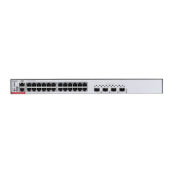
- Page 7 Hardware Installation and Reference Guide Product Overview Figure 1-1 RG-S5300-24GT4XS-E Switch Appearance Front Panel Figure 1-2 Front Panel of RG-S5300-24GT4XS-E 1. System Status LED 7. 10GE SFP+ Port 2. Management Port LED 8. Port LED 3. USB Port 4. Console Port 5.
- Page 8 Hardware Installation and Reference Guide Product Overview RG-S5300-24GT4XS-E switch adopts a left-to-right and front-to-right airflow to ensure normal operation. Maintain a minimum clearance of 100 mm (3.94 in.) around the device for air circulation. Figure 1-4 Airflow Direction Function Panel ID Color Status System is not powered on.
- Page 9 SFP+ Modules, SFP+ Cables and SFP+ BIDI Modules. SFP Module Type See Chapter 7 for details. The module types may update without prior notification. Please contact Ruijie Networks for details. AC Input Rated Voltage Range: 100 V AC to 240 V AC ...
- Page 10 Hardware Installation and Reference Guide Product Overview Dimensions (W x D x H) 442 mm x 220 mm x 43.6 mm (17.40 in. x 8.66 in. x 1.72 in.) Weight 3 kg (6.61 lbs.) Appearance The front panel of the RG-S5300-48GT4XS-E switch provides 48 10/100/1000Base-T Ethernet ports, four 10GE SFP+ ports, one management port, one Console port and one USB port.
- Page 11 Hardware Installation and Reference Guide Product Overview 1. Grounding Stud 2. AC Power Plug Power Supply The RG-S5300-48GT4XS-E switch has a built-in power supply module. The back panel has an AC power plug. Cooling The RG-S5300-48GT4XS-E switch adopts a left-to-right and front-to-right airflow to ensure normal operation. Maintain a minimum clearance of 100 mm (3.94 in.) around the device for air circulation.
- Page 12 SFP Modules and SFP BIDI Modules SFP+ Modules, SFP+ Cables and SFP+ BIDI Modules. SFP Module Type See Chapter 7 for details. The module types may update without prior notification. Please contact Ruijie Networks for details. Power Supply Module Slots RG-PA600I-P-F...
- Page 13 Hardware Installation and Reference Guide Product Overview Frequency: 50 Hz/60 Hz Rated Current Per Circuit: 8 A 10GBase-R Capable SFP+ Port 1000Base-X Capable Supported All RJ45 ports are PoE+ capable and each port provides up to 30 W of power. The maximum power depends on the configured power supply.
- Page 14 Hardware Installation and Reference Guide Product Overview Front Panel Figure 1-10 Front Panel of RG-S5310-24GT4XS-P-E 1. System Status LED 7. USB Port 2. Management Port LED 8. Console Port 3. PWR1 Status LED 9. Management Port 4. PWR2 Status LED 10.
- Page 15 Hardware Installation and Reference Guide Product Overview The switch can be powered on by either one power supply module or dual power supply modules. If both power supply modules are used, the switch works in the power redundancy mode. Cooling The RG-S5310-24GT4XS-P-E switch adopts a left-to-right and front-to-right airflow to ensure normal operation.
- Page 16 SFP Modules and SFP BIDI Modules SFP+ Modules, SFP+ Cables and SFP+ BIDI Modules. SFP Module Type See Chapter 7 for details. The module types may update without prior notification. Please contact Ruijie Networks for details. Power Supply Module Slots...
- Page 17 Hardware Installation and Reference Guide Product Overview RG-PA600I-P-F AC Input Rated Voltage Range: 200 V AC to 240 V AC Maximum Voltage Range: 176 V AC to 264 V AC Frequency: 50 Hz/60 Hz Rated Current Per Circuit: 8 A ...
- Page 18 Hardware Installation and Reference Guide Product Overview EMI Certification GB9254-2008CLASS A Safety Regulation GB4943-2011 Compliance Dimensions (W x D x H) 442 mm x 420 mm x 43.6 mm (17.40 in. x 16.54 in. x 1.72 in.) Weight 4.6 kg (10.14 lbs.) Appearance The front panel of the RG-S5310-48GT4XS-P-E switch provides 48 10/100/1000Base-T Ethernet ports (PoE+ capable), four 10GE SFP+ ports, one management port, one Console port and one USB port.
- Page 19 Hardware Installation and Reference Guide Product Overview 1. Grounding Stud 2. Power Supply Module Slot 1 (A filler panel is required if the slot is vacant.) 3. Power Supply Module Slot 2 (A filler panel is required if the slot is vacant.) Power Supply The RG-S5310-48GT4XS-P-E switch supports dual power supply modules.
- Page 20 Hardware Installation and Reference Guide Product Overview 1. The temperature at the air intake and exhaust Solid Red vents exceeds the threshold greatly. 2. The system is not functioning properly. The power supply module is not seated. The power supply module is seated and Solid Green providing power to the switch.
-
Page 21: Power Supply Module
Hardware Installation and Reference Guide Product Overview 1.5 Power Supply Module 1.5.1 RG-PA600I-P-F Module The RG-S5310-24GT4XS-P-E and RG-S5310-48GT4XS-P-E switches support the RG-PA600I-P-F power module. The RG- PA600I-P-F is an AC module (AC/HVDC input and DC output) providing an output voltage of 56 V and an output power of up to 600 W (PoE power: 370 W). - Page 22 Hardware Installation and Reference Guide Product Overview Undervoltage protection, output overcurrent protection, output overvoltage protection and Protection output short circuit protection I2C Communication The switch can communicate with the power supply module through I2C. System supports 1+1 power redundancy when the power consumption is less than 370 W. Power Redundancy Dual power supply modules are connected in parallel for current sharing.
- Page 23 Hardware Installation and Reference Guide Product Overview Power 370 W (Dual power supply modules: 740 W) Consumption Dimensions (W x D x H) 196 mm x 90 mm x 40 mm (7.72 in. x 3.54 in. x 1.57 in.) Weight 0.9 kg (1.98 lbs.) Operating Temperature -10°...
- Page 24 Hardware Installation and Reference Guide Product Overview Specifications Item Specification Power Supply Model RG-PA1000I-P-F Switch Model RG-S5310-24GT4XS-P-E, RG-S5310-48GT4XS-P-E Rated Input Voltage AC Input: 100 V AC to 240 V AC, 50 Hz/60 Hz Range HVDC Input: 240 V DC Maximum Input Voltage AC Input: 90 V AC to 264 V AC, 47 Hz/63 Hz Range HVDC Input: 192 VDC to 288 VDC...
- Page 25 Hardware Installation and Reference Guide Product Overview The power supply module is not connected with a power cord. A power output error occurs, including fan fault, output Output Status LED short-circuit, output overcurrent protection, output Solid Red overvoltage protection, power supply failure and overheat protection.
-
Page 26: Preparing For Installation
Hardware Installation and Reference Guide Preparing for Installation 2 Preparing for Installation 2.1 Safety Precautions To avoid personal injury and device damage, carefully read the safety precautions before you install the switch. The following safety precautions may not cover all possible dangers. 2.1.1 General Safety Precautions ... -
Page 27: Installation Environment Requirements
Hardware Installation and Reference Guide Preparing for Installation (that is, Action current of the leakage protector/2/Maximum leakage current of each power supply = 30/2/1.75 ≈ 8.57). In other words, the leakage protector with 30 mA rated action current supports no more than eight power supplies. In this case, the 16 power supplies in the system require at least two leakage protectors with 30 mA rated action current and each leakage protector supports eight power supplies. -
Page 28: Cleanliness Requirements
Hardware Installation and Reference Guide Preparing for Installation In an environment with high relative humidity, the insulating material may have poor insulation or even leak electricity. In an environment with low relative humidity, static electricity is prone to occur and damage the internal circuits of the switch. - Page 29 Hardware Installation and Reference Guide Preparing for Installation Route interface cables only indoors to prevent signal ports from getting damaged by overvoltage or overcurrent caused by lightning strikes. 2.2.5 Grounding Requirements A proper grounding system is the basis for stable and reliable running and is indispensable for preventing lightning strikes and interference.
-
Page 30: Emi Requirements
2.4 Tools Phillips screwdriver, slotted screwdriver, related copper and fiber-optic cables, bolts, Common Tools diagonal pliers, cable ties Special Tools ESD tools Meter Multimeter No tool kit is delivered with the RG-S5300-E series switches. -
Page 31: Installing The Switch
Hardware Installation and Reference Guide Installing the Switch 3 Installing the Switch Ensure that requirements in Chapter 2 are all met. -
Page 32: Installing Procedure
Hardware Installation and Reference Guide Installing the Switch 3.1 Installing Procedure Prepare for installation Prepare for installation Install the rack Mount the switch into the rack Ground the switch Install the modules Turn on the power Connect the cables Bundle the cables Verify the installation... -
Page 33: Before You Begin
3.3.1 Mounting the Switch in a Rack All models of the RG-S5300-E series switches can be installed in a standard 19-in. four-post EIA rack. Mount the switch in the rack with the front panel face forward. Use a Phillips-head screw driver to secure a bracket to each side of the switch with two screws. - Page 34 Hardware Installation and Reference Guide Installing the Switch Figure 3-2 Installing Cage Nuts and Screws Secure the switch on the rack rails by tightening the screws. Figure 3-3 Tightening Screws Insert screws into the other two cage nuts and tighten them. Figure 3-4 Tightening Other Screws...
-
Page 35: Mounting The Switch On The Wall
Installing the Switch 3.3.2 Mounting the Switch on the Wall All models of the RG-S5300-E series switches can be installed on the wall. Rotate the brackets by 90 degrees and secure the brackets to the switch by using the screws. -
Page 36: Installing And Removing A Power Supply Module
Hardware Installation and Reference Guide Installing the Switch 3.4 Installing and Removing a Power Supply Module Wear an anti-static wrist strap before the following operation. Installing the AC Power Supply Module Remove the module from its packing materials and make sure the input specifications meet requirements. Remove the blank filler panel in the empty slot. - Page 37 Hardware Installation and Reference Guide Installing the Switch the guide rail until you feel the connector snap into place. The two screws of the DC power supply are the input of the power supply. Remove the protective cover of the power input terminal, loosen the screw, and connect the terminals of the power cord.
-
Page 38: Grounding The Switch
Hardware Installation and Reference Guide Installing the Switch Pull the module out of the slot gently. Install the filler panel in the empty slot to allow for adequate airflow. 3.5 Grounding the Switch Connect the PGND to the grounding lug of the rack and then connect the grounding lug to the grounding bar of the equipment room. -
Page 39: Verifying Installation
Hardware Installation and Reference Guide Installing the Switch Connect the RJ45 connector of an Ethernet cable to the Ethernet port on the device, and the other end to a PC. Insert the single-mode or multi-mode fiber into the corresponding interface according to the panel identification, and distinguish the transmitting and receiving ends of the fiber-optic cable. -
Page 40: Setting Up Configuration Environment
Hardware Installation and Reference Guide Verifying Operating Status 4 Verifying Operating Status 4.1 Setting up Configuration Environment Setting up Configuration Environment Connect the PC to the management port of the switch with an Ethernet cable. Figure 4-1 Configuring Environment Connecting an Ethernet Cable ... - Page 41 Hardware Installation and Reference Guide Verifying Operating Status In the Name box, enter the new connection name and click OK. The Connect to dialog will appear. From the Connect using drop-down list, select a COM port to be used. Figure 4-3 Figure 4-3 Click OK.
-
Page 42: Powering On Switch
Hardware Installation and Reference Guide Verifying Operating Status Click OK and the HyperTerminal window will appear. 4.2 Powering on Switch Checklist before Power-on The switch is fully grounded. The power cord is properly connected. The power cord retention clip secures the input power cord to the power supply. ... -
Page 43: Monitoring And Maintenance
Port configuration and status Fan and power supply status System temperature For the monitoring commands, see RG-S5300-E Series Switches Configuration Guide. 5.2 Maintenance Cooling System Maintenance If the fan module fails, an alarm will be generated. ... - Page 44 Hardware Installation and Reference Guide Monitoring and Maintenance Replacing Lithium Battery The device has a built-in lithium battery to maintain the real-time clock without external power to the switch. To replace the lithium battery, contact technical support personnel. Replacing the battery with the wrong type may cause explosion or danger. If the battery is damaged, please replace it with the same type.
-
Page 45: Troubleshooting Flowchart
Check the installation of other modules Check the LEDs on the device Check serial port connection and parameters Check the cable connection Contact Technical Support of Ruijie Networks 6.2 Troubleshooting Fault 1: The login password is forgotten. Symptom Failed to log into the system. - Page 46 Check whether the configuration of the serial port on the HyperTerminal is consistent with that in Configuration Guide. If there is still no output on the serial port, please contact Ruijie technical support. Fault 4: The serial port console output is garbled.
- Page 47 Hardware Installation and Reference Guide Troubleshooting Check whether the receiving end and transmitting end are reversed. The transmitting end of a fiber port must be connected to the corresponding receiver at the other end. You can confirm both ends by exchanging the connection order of two fiber-optic cables.
- Page 48 Hardware Installation and Reference Guide Appendix 7 Appendix 7.1 Connectors and Media 1000BASE-T/100BASE-TX/10BASE-T The 1000BASE-T/100BASE-TX/10BASE-T is a 10/100/1000 Mbps auto-negotiation port that supports auto MDI/MDIX Crossover. Compliant with IEEE 802.3ab, 1000BASE-T requires Category 5e 100-ohm UTP or STP (STP is recommended) with a maximum distance of 100 meters (328 feet).
- Page 49 Hardware Installation and Reference Guide Appendix Fiber Connection You can choose single mode or multimode fibers according to the module types. Figure 7- shows connection of fiber-optic cable. Figure 7-3 Fiber-Optic Cable Connection...
-
Page 50: Mini-Gbic Modules
We provide appropriate SFP modules (Mini-GBIC modules) according to the port types. You can select the module to suit your specific needs. Besides, the Mini-GBIC-GT module is also supported. The following models and technical specifications of some SFP modules are listed for your reference. See Ruijie Transceiver Installation and Reference Guide for details. - Page 51 Hardware Installation and Reference Guide Appendix MINI-GBIC-LH40- SMF2 (LC 1310 SM1310 connector) MINI-GBIC-ZX50- SMF2 (LC 1550 SM1550 connector) MINI-GBIC-ZX80- SMF2 (LC 1550 SM1550 connector) MINI-GBIC-ZX100- SMF2 (LC 1550 SM1550 connector) Table 7-3 SFP Copper Module Standard 1000Base-T SFP Module Support DDM (Yes/No) 1000Base-T Mini-GBIC-GT Table 7-4 Cabling Specifications...
- Page 52 Hardware Installation and Reference Guide Appendix MINI-GBIC- SMF2 (LC connector) 9/125 80 km ZX80-SM1550 MINI-GBIC- SMF2 (LC connector) 9/125 100 km ZX100-SM1550 SDH155-SFP- MMF1 (MPO connector) 62.5/125 500 m SX-MM850 SDH155-SFP- MMF1 (MPO connector) 62.5/125 2 km SX-MM1310 SDH155-SFP- SMF2 (LC connector) 9/125 15 km LH15-SM1310...
-
Page 53: Sfp Modules
We provide appropriate SFP+ modules according to the port types. You can select the module to suit your specific needs. The following models and technical specifications of some SFP+ modules are listed for your reference. See Ruijie Transceiver Installation and Reference Guide for details. - Page 54 Hardware Installation and Reference Guide Appendix 500 (OM2) 82 m 400 (OM1) 66 m XG-SFP-SR- MMF1 (MPO connector) 50/125 2000 (OM3) 300 m SM1270-BIDI XG-SFP-SR- MMF1 (MPO connector) 50/125 2000 (OM3) 300 m SM1330-BIDI XG-SFP-LR- SMF2 (LC connector) 9/125 10 km SM1270-BIDI XG-SFP-LR- SMF2 (LC connector)
- Page 55 Hardware Installation and Reference Guide Appendix Speed/Distance Paring Models XG-SFP-SR-SM1270-BIDI 10-Gigabit/300 m XG-SFP-SR-SM1330-BIDI XG-SFP-LR-SM1270-BIDI 10-Gigabit/10 km XG-SFP-LR-SM1330-BIDI BIDI modules must be used in pairs. If XG-SFP-SR-SM1270-BIDI is used at one end, then XG-SFP-SR-SM1330- BIDI must be applied to the other end.
-
Page 56: Lightening Protection
Hardware Installation and Reference Guide Appendix 7.4 Lightening Protection Installing AC Power Arrester (Lightning Protection Power Strip) The AC power port must be connected to an external lightning protection power strip to prevent the switch from being struck by lightning when the AC power cord is introduced from the outdoor and directly connected to the power port of the switch. - Page 57 Hardware Installation and Reference Guide Appendix Please connect an Ethernet port arrester to the switch to prevent the damage by lightning before connecting an outdoor Ethernet cable to the switch. Tools: Phillips screwdrivers or flat-head screwdriver, multimeter, and diagonal pliers Installation Steps: Tear one side of the protective paper for the double-sided adhesive tape and paste the tape to the housing of the Ethernet port arrester.
- Page 58 Hardware Installation and Reference Guide Appendix Incomplete arrester installation. If there is more than one port connected to the peer device on the switch, arresters need to be installed on all connection ports for the purpose of lightning protection.
- Page 59 Hardware Installation and Reference Guide Appendix 7.5 Cabling When the switch is installed in a standard 19-inch rack, secure the cables around the cable management brackets. Top cabling or bottom cabling is adopted according to the actual situation in the equipment room. All transferred cable connectors should be placed at the bottom of the rack in an orderly manner instead of outside the rack that is easy to touch.
- Page 60 Hardware Installation and Reference Guide Appendix Cables of different types (such as power cords, signal cables, and ground cables) should be separated in cabling and bundling. Mixed bundling is disallowed. When they are close to each other, it is recommended to adopt crossover cabling.
- Page 61 Hardware Installation and Reference Guide Appendix The power cords connecting moving parts such as door grounding wires should be reserved with some access after being assembled to avoid suffering tension or stress. After the moving part is installed, the remaining cable part should not touch heat sources, sharp corners, or sharp edges.
-
Page 62: Site Selection
Hardware Installation and Reference Guide Appendix 7.6 Site Selection The equipment room should be at least 5 km away from heavy pollution sources, such as the smelter works, coal mine, and thermal power plant. The equipment room should be at least 3.7 km away from medium pollution sources, such as the chemical factory, rubber factory, and electroplating factory.
Need help?
Do you have a question about the RG-S5300-E Series and is the answer not in the manual?
Questions and answers