
Related Manuals for NTI ST-IPC6FOUSB4K-POE


Summary of Contents for NTI ST-IPC6FOUSB4K-POE
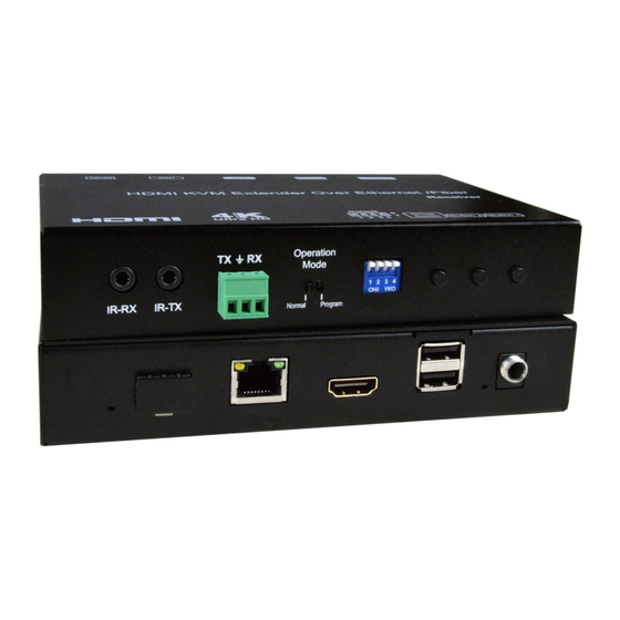
- Page 1 ST-IPC6FOUSB4K-POE 4K 10.2Gbps HDMI USB KVM Extender Over IP via CATx Cable With POE & Video Wall Support Product Manual ST-IPC6FOUSB4K-R-POE View of Remote Only, Front and Rear MAN433 REV 4/11/23...
-
Page 2: Table Of Contents
Table of Contents Introduction…………………………………………………………………...3 Features………………………………………………………………………3 Package Contents……………………………………………………..…….3 Cables Available..…………………………………………………………...4 Hardware Description…………………………………………….…………5 5.1 Transmitter……………………………………………………………..…..5 5.2 Receiver………………………………………………………………..…..6 5.3 Descriptions Buttons…………………………………………………..…..7 Installation…………………………………………………………………...11 6.1 Device Connection……………………………………………………….11 6.2 PC Tool Instructions ………………………………………………..… 14 6.2.1 Multicast…………………………………………………………16 6.2.2 Group ID…………………………………………………………16 6.2.3 Video Wall ………………………………………………………17 6.3 IP Configuration……………………………………………………..…18 Web User Interface Configuration………………………………………..21 7.1 System………………………………………………………………….21 7.1.1... -
Page 3: Introduction
1. INTRODUCTION The XTENDEX® 4K HDMI USB KVM Over IP Extender provides remote KVM (USB keyboard, USB mouse, and 4Kx2K HDMI monitor) access to a USB computer up to 394 feet (120 meters) over a Gigabit network using a single CAT5e/6/6a/7 cable. The extender consists of the ST-IPC6FOUSB4K-L-POE local unit that connects to a computer and the ST-IPC6FOUSB4K-R-POE remote unit that connects to an HDMI monitor, USB keyboard, and USB mouse. -
Page 4: Cables Available
4. CABLES AVAILABLE Interface cables between the computer/display and the transmitter/receiver are required for proper operation. Supports cable lengths to 20 feet for 4K resolutions and lengths to 50 feet for 1080p@60Hz using passive HDMI cables. Use HD-xx-MM cable to connect an HDMI source or display (not included). ... -
Page 5: Hardware Description
5. HARDWARE DESCRIPTION 5.1 Transmitter 1) Power input port 2) Power input indicator 3) USB 4) HDMI input 5) Ethernet port 6) Fiber Out 7) Indicator of status 8) IR-RX port 9) IR-TX port 10) RS232 port 11) Normal: For serial over IP; Program: For serial control or getting debug information 12) 4 bit Dip switch 13) Group Switch... -
Page 6: Receiver
5.2 Receiver 1) Power input port 2) Power input indicator 3) USB 4) HDMI output 5) Ethernet port 6) Fiber In 7) Indicator of status 8) IR-RX port 9) IR-TX port 10) RS232 port 11) Normal: For serial over IP; Program: For serial control or getting the debug information 12) 4 bit Dip switch 13) Group Switch... -
Page 7: Descriptions Buttons
5.3 Button Descriptions: (Host: Transmitter; Client: Receiver) Button State for Unicast Mode: HDMI Extender: * Item will be described in Descriptions on page 8 Unicast Digital Button State Transmitter Receiver Button One : Button Two : Button One : Button Two : Momentary Press Toggle Video Mode/ Toggle Video Mode/... - Page 8 Descriptions: Feature /Button Feature Descriptions When System is all setup, a short press of this button will change between remote / local loopback Remote/Loopback When System is all setup and video is displayed at the client side, a long press of this button Snoop (on/off) will cause the local loop back port to be enabled for Snooping feature.
- Page 9 Button State for Multicast Mode: HDMI Extender: * Item will be described in Descriptions on page 10 Multicast Digital Button State Transmitter Receiver Button One: Button Two: Button One: Button Two: Momentary Press Remote/Loopback* Video Mode/ Link on: Link Video Mode/ Graphic Mode* Link off: Unlink Graphic Mode*...
- Page 10 Descriptions: Feature /Button Feature Descriptions When System is all setup, a short press of this button will change between remote / local loopback Remote/Loopback When System is all setup and video is displayed at the client side. Long Press of this button will Snoop (on/off) cause the local loop back port to be enabled for Snooping feature.
-
Page 11: Installation
6. INSTALLATION 6.1 Device Connection 1. Verify the power supply is unplugged. Set up the group of the transmitter with the corresponding receiver for signal extension and display. Connect the Transmitter to a video source with HDMI cable, and connect the Receiver to a monitor or display with an HDMI cable. - Page 12 ◆ Application Pattern ■ Unicast ■ Multicast a. Video Distribution...
- Page 13 b. Matrix Distribution c. Billboard & Kiosk, PC to HDMI and USB Interactive Monitor...
-
Page 14: Pc Tool Instructions
Step 1: See section 6.3 for setup. If using a network switch, the HDMI extender and computer must be in the same domain. Step 2: Download the "st-ipc6fousb4k-poe-control.zip" from the NTI website (https://www.networktechinc.com/4k-hdmi-usb-poe- extender.html#tab-4) and unzip it to your computer. Locate "4KOverIP2V5.exe"... - Page 15 Step 4: Choose the TX or RX name (one at a time). Step 5: If desired, change the Hostname ID, Casting Mode and/or IP Mode on the graphic tool interface. Step 6: Once changes are made, click “Apply”.
-
Page 16: Multicast
6.2.1 Multicast Click "Multicast" on the graphic tool interface if you are configuring for One- to-Many or Many-to-Many application. 6.2.2 Channel Change the Channel number to be the same for the Transmitter and all Receivers to view the same source. Each Transmitter will be assigned a different Channel number. -
Page 17: Video Wall
6.2.3 Video Wall 1. Set the Transmitter and Receiver with same Channel numbers. 2. Change the “Vertical Monitor Count” and “Horizontal Monitor Count” to Note:Using this tool, the maximum video wall size is 5X5. create a video wall. For example, if you need create a 2x2 video wall, set the “Vertical Monitor Count”... -
Page 18: Ip Configuration
4. Select the RX and drag it to the corresponding position indated by the reference blocks. The position will be included in the OSD shown on the screen. 6.3 IP Configuration The 4K HDMI & USB Over IP Extender can be configured via LAN provided the Transmitter and Receiver are in the same subnet. - Page 19 2. Connect the TX and RX to the Ethernet switch, then also connect the PC to the Ethernet switch. Because this unit supports DHCP, different units may have different server-assigned IP addresses, so the first thing we need know is the IP address of each unit. There are two ways to get the IP address A) Using the “Node List”...
- Page 20 B) Using the OSD. Connect all devices using proper cables except the video source. Figure 2. Demonstrate the 4K HDMI & USB Over IP Extender After power-up, the device information including the Transmitter and Receiver IP address will be shown in the lower right corner. Make note of the Transmitter and Receiver IP address(es) on each monitor screen and then connect the HDMI video source cable to the Transmitter.
-
Page 21: Web User Interface Configuration
3. The administrator can enter a Transmitter or Receiver IP address into the address bar of the web browser (we recommend using Google Chrome) to enter the Extender's Web UI (User Interface). If the link is successful, the user will see the Web UI as shown in Figure 4. Figure4. -
Page 22: Update Firmware
7.1.2 [Update Firmware] To update the firmware of the connected extender, please click on the [Select File] to select the firmware and click on [Upload] to upload the firmware and (No new firmware is currently available.) update accordingly. Transmitter Firmware Update: please select [webfwh.bin] to update ... -
Page 23: Utilities
7.1.3 [Utilities] There are some functions under Utilities: Factory Default: Click on to return the device to factory default settings when needed. Reboot: Click on to reboot the extender (RX or TX) Console API Command: Input Linux command for advanced setting... -
Page 24: Statistics
7.1.4 [Statistics] Indicates the extender link and working status... -
Page 25: Video Wall
7.2 Video Wall To set up the video wall application 7.2.1 [Basic Setup] Bezel and Gap Compensation: Dimension of the screen (inside and outside width and height) OW: outside width OH: outside height VW: viewable width VH: viewable height NOTE: 1) The viewable width must be less than the outside width, and the viewable height must be less than the outside height. - Page 26 Wall Size and Position Layout: Select number of vertical and/ or horizontal monitors, row position and column position. Vertical monitor number 1~8, horizontal monitor number 1~16...
- Page 27 Preferences: Select the video to "fit in" the screen or "stretch out" and then provide the rotation angle (if applicable- leave at 0 if not).
- Page 28 Apply To: 1) All: Configure all Transmitter and Receiver in the same Group IP. 2) This (Local): The IP you input into address bar of web browser. 3) Hosts or Clients: select which Transmitter or Receiver you want to configure.
-
Page 29: Advanced Setup
7.2.2 [Advance Setup]... - Page 30 Before entering the “Advanced Setup”, please complete the “Basic Setup” as follows: Step 1: In “Basic Setup”, select Vertical and Horizontal Monitor Count. For example Vertical Monitor Count = 3, Horizontal Monitor Count = 5 Step 2: In “Advanced Setup”, choose the target (receiver) of the video wall to control...
- Page 31 If incorrect settings are made, press the “Reset” in Reset to Basic Setup function. Setup the video output to “Fit In’ or “Stretch Out” mode in the screen Setup the rotation angle of the video output Set up the vertical and horizontal position number of the monitor based on the video wall layout.
- Page 32 Setup the column position of monitor, numbered from 0 to the total number of horizontal monitors. Setup the video position shift and video enlarge. Horizontal Shift: Setup the video horizontal shift, Left or Right Vertical Shift: Setup the video vertical shift, Up or Down ...
-
Page 33: Network
Consol API Command: Input Linux command to do advanced setup. 7.3 Network: Update the network setup of the extender system 7.3.1 [IP Setup] Auto IP: Use to automatically assign the extender IP system for example: 169.254.xxx.xxx. -
Page 34: Casting Mode
DHCP: Use a DHCP Server to assign the IP. Static: Use the static IP setting to assign the IP address manually. 7.3.2 [Casting Mode] Select the broadcast mode of the extender application Multicast: point-to-many points or many-to-many points broadcast ... -
Page 35: Functions
7.4 Functions: Setup the video output and USB extension mode for Transmitter Setup the video output and USB extension mode for Receiver... -
Page 36: Ip Setup
7.4.1 [Video over IP]: Setup the video output mode Enable Video over IP: Check to enable video extension over IP Enable Video Wall: Check to enable the video extension for building up video wall Enable EDID Copy: This function is limited to copy just one of the receivers. ... -
Page 37: Casting Mode
Customize Scaler Output Mode for Receiver Timeout for Detecting Video Lost 7.4.2 [USB over IP]: Setup the USB extension mode Enable USB over IP: Check to enable USB extension mode over IP Operation Mode: Including “auto select mode”, “active on line” and “active per request”... -
Page 38: Serial Over Ip
7.4.3 [Serial over IP]: set up the serial extension mode Select Type 2 as operation mode Set up the baud rate for Type 2. Serial Over IP Broadcast Mode Setting... -
Page 39: Broadcast Configuration Example
8. BROADCAST CONFIGURATION SETTING There are some examples to show the setup for unicast, multicast, matrix and video wall. Broadcast setting including unicast and multicast 8.1 Multicast: To enable the USB interactive devices controlled by turns, please check “Auto select USB operation mode per casting mode” 8.2 Unicast: 8.3 Matrix: Install multiple transmitters and set the ID of these transmitters individually, then... -
Page 40: Video Wall
8.4 Video wall: A 3X5 (row x column) video wall setting example is shown here for reference. In multicast and matrix application mode, access the web user interface of the corresponding receiver to setup. 8.4.1 (Basic Setup) Please refer to “Section 6.2.1 Basic setup” and follow the steps as below. Step1: Set up the vertical monitor count to “3”... -
Page 41: Advanced Setup
8.4.2 Advanced Setup Select the monitor you want to control. The one you select will show “This” in green in video wall matrix layout. Take below diagram for example, the monitor we select to control here is the monitor in the upper left corner. Example for the video wall control Here’s the diagram of the actual video wall layout showing the selected monitor in the upper left corner with green outline. - Page 42 Return to the previous setup of video wall quickly when the incorrect operation has been input Reset Adjust the horizontal position of the video output, “Left/Right Shift”, the selected monitor to adjust is shown with green outline. Adjust the vertical position of the video output, “Up/Down Shift”, the selected monitor to adjust is shown with green outline.
- Page 43 Horizontal Scale Up: To scale up the video output horizontally as the monitor shown with green outline Vertical Scale Up: To scale up the video output vertically as the monitor shown with green outline...
-
Page 44: Specifications
SPECIFICATIONS Local Unit Compatible with a USB computer with Ultra-HD HDMI • output. Multiplatform support: Windows 7/8/10/11, Windows • Server 2008/2012/2016/2019/2022, Linux, FreeBSD, and MAC OS 10/11/12/13. One female HDMI connector. • One female USB Type B connector. • Two female 3.5mm ports for connecting an IR emitter and •... - Page 45 One SFP receptacle – fiber extension not supported at this • time. DIP switch for specifying unit ID. • Power Power over Ethernet: With a switch that supports PoE, a • power supply is not required at the local or remote unit. Compliant with IEEE 802.3af, class 0 standards.
-
Page 46: Warranty
WARRANTY The warranty period on this product (parts and labor) is two (2) years from the date of purchase. Please contact Network Technologies Inc at (800) 742-8324 (800-RGB-TECH) or (330) 562-7070 or visit our website at http:// www.networktechinc.com for information regarding repairs and/or returns. A return authorization number is required for all repairs/returns.
Need help?
Do you have a question about the ST-IPC6FOUSB4K-POE and is the answer not in the manual?
Questions and answers